EP0399607A2 - Système de détection de marquages - Google Patents
Système de détection de marquages Download PDFInfo
- Publication number
- EP0399607A2 EP0399607A2 EP90201275A EP90201275A EP0399607A2 EP 0399607 A2 EP0399607 A2 EP 0399607A2 EP 90201275 A EP90201275 A EP 90201275A EP 90201275 A EP90201275 A EP 90201275A EP 0399607 A2 EP0399607 A2 EP 0399607A2
- Authority
- EP
- European Patent Office
- Prior art keywords
- frequency
- signals
- signal
- period
- reproduced
- Prior art date
- Legal status (The legal status is an assumption and is not a legal conclusion. Google has not performed a legal analysis and makes no representation as to the accuracy of the status listed.)
- Granted
Links
Images


Classifications
-
- G—PHYSICS
- G11—INFORMATION STORAGE
- G11B—INFORMATION STORAGE BASED ON RELATIVE MOVEMENT BETWEEN RECORD CARRIER AND TRANSDUCER
- G11B15/00—Driving, starting or stopping record carriers of filamentary or web form; Driving both such record carriers and heads; Guiding such record carriers or containers therefor; Control thereof; Control of operating function
- G11B15/02—Control of operating function, e.g. switching from recording to reproducing
- G11B15/05—Control of operating function, e.g. switching from recording to reproducing by sensing features present on or derived from record carrier or container
- G11B15/087—Control of operating function, e.g. switching from recording to reproducing by sensing features present on or derived from record carrier or container by sensing recorded signals
-
- G—PHYSICS
- G11—INFORMATION STORAGE
- G11B—INFORMATION STORAGE BASED ON RELATIVE MOVEMENT BETWEEN RECORD CARRIER AND TRANSDUCER
- G11B27/00—Editing; Indexing; Addressing; Timing or synchronising; Monitoring; Measuring tape travel
- G11B27/10—Indexing; Addressing; Timing or synchronising; Measuring tape travel
- G11B27/11—Indexing; Addressing; Timing or synchronising; Measuring tape travel by using information not detectable on the record carrier
- G11B27/13—Indexing; Addressing; Timing or synchronising; Measuring tape travel by using information not detectable on the record carrier the information being derived from movement of the record carrier, e.g. using tachometer
-
- G—PHYSICS
- G11—INFORMATION STORAGE
- G11B—INFORMATION STORAGE BASED ON RELATIVE MOVEMENT BETWEEN RECORD CARRIER AND TRANSDUCER
- G11B27/00—Editing; Indexing; Addressing; Timing or synchronising; Monitoring; Measuring tape travel
- G11B27/10—Indexing; Addressing; Timing or synchronising; Measuring tape travel
- G11B27/19—Indexing; Addressing; Timing or synchronising; Measuring tape travel by using information detectable on the record carrier
- G11B27/28—Indexing; Addressing; Timing or synchronising; Measuring tape travel by using information detectable on the record carrier by using information signals recorded by the same method as the main recording
- G11B27/30—Indexing; Addressing; Timing or synchronising; Measuring tape travel by using information detectable on the record carrier by using information signals recorded by the same method as the main recording on the same track as the main recording
- G11B27/3009—Indexing; Addressing; Timing or synchronising; Measuring tape travel by using information detectable on the record carrier by using information signals recorded by the same method as the main recording on the same track as the main recording used signal is a pilot signal inside the frequency band of the recorded main information signal
-
- G—PHYSICS
- G11—INFORMATION STORAGE
- G11B—INFORMATION STORAGE BASED ON RELATIVE MOVEMENT BETWEEN RECORD CARRIER AND TRANSDUCER
- G11B27/00—Editing; Indexing; Addressing; Timing or synchronising; Monitoring; Measuring tape travel
- G11B27/10—Indexing; Addressing; Timing or synchronising; Measuring tape travel
- G11B27/19—Indexing; Addressing; Timing or synchronising; Measuring tape travel by using information detectable on the record carrier
- G11B27/28—Indexing; Addressing; Timing or synchronising; Measuring tape travel by using information detectable on the record carrier by using information signals recorded by the same method as the main recording
- G11B27/30—Indexing; Addressing; Timing or synchronising; Measuring tape travel by using information detectable on the record carrier by using information signals recorded by the same method as the main recording on the same track as the main recording
- G11B27/3018—Indexing; Addressing; Timing or synchronising; Measuring tape travel by using information detectable on the record carrier by using information signals recorded by the same method as the main recording on the same track as the main recording used signal is a pilot signal outside the frequency band of the recorded main information signal
-
- G—PHYSICS
- G11—INFORMATION STORAGE
- G11B—INFORMATION STORAGE BASED ON RELATIVE MOVEMENT BETWEEN RECORD CARRIER AND TRANSDUCER
- G11B27/00—Editing; Indexing; Addressing; Timing or synchronising; Monitoring; Measuring tape travel
- G11B27/10—Indexing; Addressing; Timing or synchronising; Measuring tape travel
- G11B27/34—Indicating arrangements
-
- G—PHYSICS
- G11—INFORMATION STORAGE
- G11B—INFORMATION STORAGE BASED ON RELATIVE MOVEMENT BETWEEN RECORD CARRIER AND TRANSDUCER
- G11B2220/00—Record carriers by type
- G11B2220/90—Tape-like record carriers
Definitions
- the invention relates to a system for evaluating markings, which each consist of at least one marking signal with a predetermined frequency and which are recorded together with information corresponding information signals on a magnetic tape which runs between an unwinding core and a winding core and which is used exclusively for recording purposes is driven at a constant speed driven winding core, and which identify specific locations of the information, an unwinding mandrel and a winding mandrel for driving the unwinding core and the winding core, at least one magnetic head for reproducing the recorded signals and a frequency comparison device for comparing the respective frequency of the with the Magnetic head reproduced signals supplied to the frequency comparison device with a reference frequency, which is present when a predetermined comparison condition is met he gives mark signaling signal.
- Such a system is known from a commercially available dictation device for magnetic tapes housed in cassettes. With this device, corresponding voice signals dictated by a user can be recorded on a magnetic tape.
- the user also has the option of recording markings on the magnetic tape which identify certain places in the dictation, for example the end of a dictation or a dictation point at which a correction of the dictation or an insertion into the dictation is desired.
- a marking for marking the end of a dictation consists of an essentially sinusoidal marking signal with a frequency of 40 Hz, which is recorded on the magnetic tape at the end of a dictation after the speech signals in the same track.
- a marking for identifying a dictation point to be corrected consists of the essentially sinusoidal marking signal with the frequency of 40 Hz and a further substantially sinusoidal marking signal with a frequency of 1500 Hz, both of which at the dictation point to be corrected instead of Voice signals are recorded in the same track on the magnetic tape.
- the known device has the system mentioned at the beginning for evaluating the markings recorded on the magnetic tape, the presence of a marking per se by detecting the recorded marking signal contained in all the markings with the frequency of 40 Hz.
- the magnetic tape when the dictations and the markings are recorded, the magnetic tape is driven exclusively via the winding core, which is driven by the winding mandrel at a constant first speed.
- the magnetic tape When evaluating the markings, the magnetic tape is also driven exclusively via the winding core, which is driven by the winding mandrel at a constant second speed, which is twenty times higher than the first speed. In this way, the magnetic tape is driven twenty times faster when evaluating than when recording, so that recorded markings can be found quickly. Because of this twenty times higher rotational speed, when the markings are evaluated, the recorded marking signals are frequency-transposed, so that the marking signals reproduced with a magnetic head when evaluated have a 20 times higher frequency value.
- this frequency transposition remains the same over the entire length of the magnetic tape. This means that, for example, the recorded marking signal with the frequency of 40 Hz, which is contained in all the markings, regardless of the point at which it is recorded on the magnetic tape, is always reproduced as a frequency-transposed marking signal with a frequency of 800 Hz during evaluation .
- the presence of a marking itself is recognized in the known system by determining the occurrence of the frequency-transposed reproduced marking signal at the frequency of 800 Hz, for which the known system as a frequency comparison device has a fixed mean pass frequency of 800 Hz Having filter circuit, the average pass frequency forms the reference frequency with which the respective frequency of the reproduced with the magnetic head, formed by speech signals and marking signals signals is compared, and with frequency equality, i.e. when a frequency-transposed marking signal with the frequency of 800 Hz with the magnetic head is reproduced, a signal indicating the presence of a marking is emitted at its output, which signal is used to control a shutdown device for the belt drive.
- the object of the invention is to eliminate the above-mentioned limitation and to achieve with a system of the type mentioned at the beginning with simple means that an evaluation of the markings is possible even with a changing frequency transposition of the recorded marking signals.
- the invention is characterized in that a speed sensor is coupled to the winding mandrel, which emits a speed signal with a frequency proportional to the speed of the winding core, and that the speed signal is fed to the frequency comparison device in which the frequency of the speed signal forms the reference frequency and which compares the respective frequency of the speed signal with the respective frequency of the signals reproduced with the magnetic head.
- the respective frequency of the signals reproduced with the magnetic head corresponds to the respective speed of the winding core speaking reference frequency is compared, regardless of how the magnetic tape is driven, subjected to the same frequency transposition as the frequency of the recorded marking signals, so that the frequency transposition has no effect on the frequency comparison of the two frequencies.
- An evaluation of the markings which is independent of the frequency transposition is thus achieved, so that the magnetic tape can advantageously be driven in any desired manner when evaluating the markings, for example also by driving the unwinding core at constant or variable speed or by driving the winding core at constant or variable speed.
- the frequency comparison device can have, for example, two frequency / voltage converters, one of which supplies the speed signal and the other the signals reproduced by the magnetic head, and which, in accordance with the frequency of the signals supplied to them, supply output voltages which can be detected in a voltage comparator circuit the presence of a marker can be evaluated.
- the frequency comparison device is formed with a microprocessor which, in order to compare the respective frequency of the speed signal with the respective frequency of the signals reproduced with the magnetic head, determines the respective period duration of the speed signal and the respective period duration of the signals reproduced with the magnetic head and then compares the two period durations according to a predetermined comparison condition for these two period durations and, when this comparison condition is fulfilled, emits the signal signaling the presence of a marker.
- a microprocessor provided for realizing a large number of other functions is advantageously also used as a frequency comparison device.
- the microprocessor can directly communicate the respective period of the speed signal and the respective period of the signals reproduced with the magnetic head to compare. It has proven to be particularly advantageous, however, if the microprocessor calculates a tolerance window with a lower period duration limit value and an upper period duration limit value from the determined period duration of the speed signal and the predetermined comparison condition is determined in such a way that the determined respective period duration of the signals reproduced with the magnetic head within these two Period duration limit values must lie. Such a system is advantageously insensitive to tolerances of the speed sensor and tolerances of the frequency of the marking signals reproduced.
- the microprocessor only emits the signal signaling the presence of a marker when the predetermined comparison condition is met for the two period durations.
- Such a system is advantageously insensitive to interference signals which occur briefly in the reproduction signal path of the magnetic head and which have a frequency lying in the frequency range of the reproduced marking signals.
- FIG. 1 schematically shows a dictation device for recording dictations and markings, which consist of a single marking signal with a predetermined frequency, on a magnetic tape accommodated in a cassette.
- 2 shows schematically a magnetic tape on which dictations and markings were recorded with a device according to FIG. 3 shows schematically the signal course of the marking signal, which forms a marking as it is recorded on the magnetic tape according to FIG.
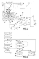
- FIG. 4 schematically shows a dictation device that has a system according to the invention for evaluating the markings recorded with a device according to FIG. 1 and contains a microprocessor.
- FIG. 5 shows a flow diagram of a program sequence which is processed in the microprocessor of the device according to FIG. 4 for evaluating the markings.
- FIG. 6 schematically shows a magnetic tape on which dictations and markings are recorded with a device which is not shown separately and which corresponds in structure to the device according to FIG. 1 are, here three different marks are recorded on the magnetic tape.
- 7 shows schematically the signal composition of the three different markings recorded on the magnetic tape according to FIG.
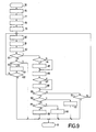
- FIG. 8 shows a dictation machine that has a further system according to the invention for evaluating the three different markings according to FIG. 7 and contains a microprocessor.
- FIG. 9 shows a flow diagram of a program sequence which is processed in the microprocessor of the device according to FIG. 8 for evaluating the markings.
- a dictation device 1 schematically shows a part of a dictation device 1, which is designed, for example, as a hand-held pocket dictation device, for a magnetic tape 3 which is accommodated in a cassette 2 which can be inserted into the device and which runs in the cassette between an unwinding core 4 and a winding core 5 .
- the cassette 2 is shown schematically in Fig. 1 with dash-dotted lines.
- dictations corresponding voice signals can be recorded on the magnetic tape 3.
- the dictation device 1 can also be used to record markings on the magnetic tape 3, which mark specific locations of the dictations, namely the ends of the dictations.
- the device 1 To drive the unwinding core 4 and the winding core 5, the device 1 has an unwinding mandrel 6 and a winding mandrel 7, each of which is non-rotatably connected to a friction wheel 8 and 9, respectively.
- a motor 10 To drive the friction wheels 8 and 9, a motor 10 is provided, which is fed from a control and regulating circuit 11, with which the direction of rotation and the speed of the motor 10 can be determined.
- control and regulating circuits are known from existing dictation machines and are therefore not shown in detail here because their structure is not essential in connection with the present invention.
- the motor 10 drives an intermediate wheel 15, which is rotatably mounted on a pivotable carrier 13 with a shaft 14, via a pin 12.
- the shaft 14 forms a drive shaft for the two friction wheels 8 and 9, with which the drive shaft 14 can optionally be brought into a force-locking drive connection by pivoting the carrier 13.
- the device 1 has a built-in microphone 16, to which a recording signal processing circuit 18 is connected via a normally closed switch 17 and is connected on the output side to a magnetic head 19 with which the voice signals corresponding to the dictations are recorded in a "recording" mode on the magnetic tape 3 are recordable.
- the device 1 has a button 20, when it is actuated, as is indicated schematically by dashed lines, a switch 21 for controlling the control and regulating circuit 11 for the motor 10 and a further switch 22 for Driving the recording signal processing circuit 18 are closed and the carrier 13 is adjusted with the drive shaft 14 toward the friction wheel 9.
- control and regulating circuit 11 By closing the switch 21, the control and regulating circuit 11 is controlled so that it feeds the motor 10 in such a way that the same via the pinch 12, the intermediate wheel 15 and the drive shaft 14, the friction wheel 9 and thus the winding mandrel 5 with a predetermined , drives a constant first speed in the direction indicated by an arrow 23, as indicated in FIG. 1.
- the recording signal processing circuit 18 is activated so that it then processes voice signals supplied to it from the microphone 16 via the switch 17 and feeds it to the magnetic head 19 for recording on the magnetic tape 3 driven by the winding mandrel 7, the magnetic tape 3 in the direction of the Arrow 24 on the magnetic head 19 and on an arranged in the direction of the magnetic tape in front of the magnetic head 19, essentially formed by a permanent magnet erasing magnetic head 25 is moved along.
- the device 1 has an oscillator 26 which is provided for generating a sinusoidal marking signal S 1 with a predetermined frequency f 1 of 40 Hz.
- a switch 28 is closed, whereby the oscillator 26 is switched on for a predetermined period of time T1 of, for example, 600 msec, the oscillator 26 then emitting a marking signal S1 to the magnetic head 19, which as a marking M1 on the magnetic tape 3rd records.
- T1 of, for example, 600 msec
- the oscillator 26 then emitting a marking signal S1 to the magnetic head 19, which as a marking M1 on the magnetic tape 3rd records.
- the marker 27 Switch 17 is opened, whereby it is achieved that at the location of the magnetic tape 3, where a mark M1 is recorded, no speech signal is recorded.
- a part of a magnetic tape 3 is shown schematically, on which two dictations are recorded in a track 29, the ends of which are each marked with a mark M1.
- Each of these markers M 1 consists of the sinusoidal marking signal S 1 with the frequency f 1 of 40 Hz and with the duration T 1 of 600 msec, as indicated in FIG. In this case, therefore, each marker signal S1 consists of twenty-four (24) periods.
- the marks M1 are recorded in the same track as the voice signals in this case.
- the recorded voice signals are, as is customary in such dictation machines, in a frequency range between about 200 Hz and 6 kHz, so that the frequency of the marking signal S 1 of 40 Hz is clearly outside the frequency range of the recorded voice signals. It should be mentioned that the markings M 1 do not have to be recorded in the same track as the speech signals, but can also be recorded in a separate track.
- FIG. 4 schematically shows part of an evaluation dictation device 30, which is designed, for example, as a table dictation device and which serves to reproduce voice signals recorded on the magnetic tape 3, which can be written down by a typist.
- the device 30 contains a system 31 according to the invention for evaluating markings, as they have been recorded on the magnetic tape 3 with a device according to FIG.
- the system 31 for evaluating the markings is described in detail below.
- the device 30 like the device according to FIG. 1, has an unwinding mandrel 6 and a winding mandrel 7, each of which is connected to a friction wheel 8 or 9 in a rotationally fixed manner.
- a motor 10 is provided, which is fed from a control and regulating circuit 11 and which drives an idler gear 15 via a pinch 12, which is rotatably supported by a shaft 14 on a pivotable carrier 13, the shaft 14 also being a drive shaft for forms the two friction wheels 8 and 9.
- a magnetic head 19 is provided to play back on the magnetic tape 3 in this
- the device 30 has a button 32 for switching on the "playback" operating mode.
- a switch 33 for controlling the control and regulating circuit 11 is closed and the carrier 13 with the drive shaft 14 is adjusted toward the friction wheel 9.
- the control and regulating circuit 11 for the motor 10 is driven so that it feeds the motor 10 in such a way that it uses the pinch 12, the intermediate wheel 15 and the drive shaft 14, the friction wheel 9 and thus the winding mandrel 7 drives at the same predetermined constant first speed as when recording voice signals and marking signals in the direction indicated by arrow 23, as indicated in FIG.
- the magnetic tape 3 in the "play" mode is also driven exclusively via the winding mandrel 7, which is driven at the constant first speed, and the winding core 5, the magnetic tape 3 being moved along the magnetic head 19 in the direction of the arrow 24.
- the signals sampled by the magnetic head 19 are fed to a reproduction signal processing circuit 34, which feeds a loudspeaker 35 for the acoustic reproduction of the recorded dictations.
- the device 30 contains a system 31 for evaluating marks M 1 recorded on the magnetic tape 3, in order to be able to find these marks and consequently the ends of the dictations marked therewith simply and quickly.
- the device 30 has a button 36 for switching on an “evaluation” operating mode. By pressing the button 36, a switch 37 and a switch 38 are closed, as is indicated schematically in FIG. 4 by dashed lines, and the carrier 13 with the drive shaft 14 is adjusted toward the friction wheel 8.
- the control and regulating circuit 11 for the motor 10 is controlled so that it feeds the motor 10 in such a way that it uses the pinch 12, the intermediate wheel 15 and the drive shaft 14, the friction wheel 8 and thus the unwinding mandrel 6 in one Direction arrow 39 drives at a predetermined constant second speed, which has a value twenty times higher than the first speed with which the winding mandrel 7 is driven during recording and playback.
- the magnetic tape 3 when evaluating the markings, the magnetic tape 3 is driven exclusively via the unwinding mandrel 6 and the unwinding core 4, so that when evaluating the markings, the magnetic tape 3 is in the opposite direction to when the markings were recorded, that is to say counter to the direction of the arrow 24 is moved along the magnetic head 19, the magnetic tape 3 when evaluating the markings due to the 20 times higher speed of the unwinding mandrel 6 also has a higher travel speed than when recording.
- the speed of movement of the magnetic tape 3 increases when evaluating the markings with increasing winding diameter on the unwinding core 4, whereas when the markings are recorded, the speed of movement of the magnetic tape increases with increasing winding diameter on the winding core 5.
- the marking signals S 1 recorded on the magnetic tape with the frequency of 40 Hz when evaluating due to the changing frequency transposition are reproduced as frequency-transposed marking signals in a frequency range from 300 Hz to 2000 Hz.
- the drive of the magnetic tape 3 for evaluating markings can also take place via the winding mandrel 7, which is then also driven, for example, at a speed which is twenty times higher than that of the recording. This also results in a frequency transposition of the reproduced marking signals, which remains constant over the entire length of the magnetic tape.
- the button 38 is closed by pressing the button 36.
- the signals reproduced by the magnetic tape 3 with the magnetic head 19, in this case voice signals and marking signals are fed to an amplifier stage 40.
- the output signals of the amplifier stage 40 are fed to a pulse shaper 41, which outputs at its output pulse-shaped output signals which are fed to a frequency comparison device 42 at an input 43 thereof.
- the frequency comparison device 42 is advantageously simply formed with a microprocessor, which fulfills a multitude of tasks in the device, but which are not dealt with, since they are not essential in connection with the present invention.
- the microprocessor 42 serves as a frequency comparison device for comparing the respective frequency of the frequency-transposed signals reproduced with the magnetic head 19 and fed to the input 43 as pulse-shaped signals with a reference frequency, the microprocessor 42, when a predetermined comparison condition is met, signaling the presence of a marker outputs at an output 44.
- This signal at the output 44 causes, for example, a light-emitting diode 45 to light up for a predetermined period of time, as a result of which the finding of a marking is indicated optically.
- This signal at the output 44 can also be displayed acoustically or be supplied to the control and regulating circuit 11 for the motor 10, the control and regulating circuit 11 switching off the supply of the motor 10 when this signal occurs, so that the Motor 10 is stopped and the drive of the magnetic tape 3 is stopped when a mark is found.
- the system 31 for evaluating the markings M 1 now has a speed sensor 46 coupled to the winding mandrel 7.
- the speed sensor 46 has a toothed disc 47, which is advantageously simply connected to the winding mandrel 7 in a rotationally fixed manner.
- the disk 47 can also be coupled to the winding mandrel 7 via a drive connection 48, for example a pinhole.
- the GE serrated disk 47 interacts with its teeth with a symbolically represented photoelectric scanner 49 of the speed sensor 46.
- the speed sensor 46 When the disk 47 is driven, its teeth periodically interrupt a light beam in the scanner 49, which emits a periodic speed signal with a frequency proportional to the speed of the winding mandrel 7 and thus of the winding core 5.
- the design of the speed sensor 46 is such that, in the event that the winding mandrel 7 is driven by the motor 10 at the first predetermined speed, as is the case when recording, it outputs a speed signal with a predetermined frequency f G , which is in a predetermined ratio to the frequency f1 of 40 Hz of the marking signal S1.
- the equation f G k.f 1 is thus fulfilled, where k is a certain factor.
- the frequency f G can be 20 Hz, so that the factor k is then 0.5, because the frequency f 1 of the marking signal S 1 was chosen to be 40 Hz.
- a capacitive, inductive or otherwise effective speed sensor can also be provided.
- the speed sensor 46 Since the speed sensor 46 is coupled to the winding mandrel 7, which is driven by the motor 10 at the constant first speed when recording the markings M 1, when driving the unwinding mandrel 6 from the motor 10, as is the case when evaluating the markings M 1 in the present device 30 the case is, the frequency of the speed signal generated by the speed sensor 46 is subjected to the same frequency transposition as the signals reproduced by the magnetic head 19, including the marking signals S 1. Therefore, if the frequency-transposed signals reproduced by the magnetic head 19 are compared in terms of frequency with the frequency-transposed speed signal of the speed sensor 46 during evaluation, the frequency transposition applied to the two frequency-transposed signals in the same way has no influence on the frequency comparison.
- the frequency comparison between these two frequency-transposed signals is therefore independent of the frequency transposition performed.
- the speed signal of the speed sensor 46 coupled to the winding mandrel 7 is transmitted via a Ver stronger 50 and a pulse shaper 51 as a pulse-shaped signal to the microprocessor 42 forming the frequency comparison device at a further input 52 of the same.
- the respective frequency of the frequency-transposed speed signal now forms the reference frequency in the microprocessor 42 and the microprocessor 42 compares the respective frequency of the speed signal used as the reference frequency with the respective frequency of the signals reproduced with the magnetic head 19, i.e. the frequency-transposed speech signals and the frequency-transposed marking signals, their frequency is always outside the frequency range of the frequency-transposed speech signals.
- a program sequence is described below with reference to FIG. 5, which is processed in the microprocessor 42 in the “evaluation” operating mode for evaluating the markings.
- the activation of the "evaluation” operating mode is reported to the microprocessor 42 by pressing the button 36 to switch on the “evaluation” operating mode, as is indicated in FIG. 4 by a dashed line.
- the program sequence is started at block 53.
- an internal time counter Z Z is set to the value zero.
- a period counter Z P is set to the value zero.
- the respective duration T2 of a period of the pulse generator emitted by the speed sensor 46, the input 52 of the microprocessor 42 and the pulse-frequency-transposed speed signal is determined and stored in a register R1.
- a tolerance window with an upper period duration limit value T3 and a lower period duration limit value T4 is calculated in block 57 from the determined respective period duration T2 of the frequency-transposed speed signal.
- the factor k is determined by the frequency ratio f G : f 1, as described above has already been explained.
- the respective duration T 58 of a period of the frequency-transposed signals reproduced with the magnetic head 19 and fed to the input 43 of the microprocessor 42 is then determined at block 58 and stored in a register R4.
- the two determined respective periods T2 and T5 are compared according to a predetermined comparison condition for the two periods.
- This predetermined comparison condition is set in the microprocessor 42 so that the determined period T5 of the signals reproduced with the magnetic head 19 must lie between the two period duration limits T3 and T4 calculated from the determined period T2 of the speed signal.
- the comparison condition k.T2.0.9 ⁇ T5 ⁇ k.T2.1.1 must be met.
- the comparison condition checked in block 59 is fulfilled, that is to say a period of a frequency-transposed reproduced marking signal S 1 has been determined, then a check is made in block 61 as to whether the counter reading of the period counter Z p has the value zero. If this is the case, the internal time counter Z z is then started at block 62, which is then automatically incremented according to the elapsing time. After block 62, the program flow continues at block 63, which is also the case if it is determined at block 61 that the counter reading of the period counter Z P deviates from the value zero.
- the time counter Z Z is only present when the counter reading is zero in the period counter Z P , that is to say after the first determination of a period of a fre playback transposed marker signals S1, is started.
- the period counter Z P is incremented.
- the period counter Z p counts in this way how often the comparison condition checked at block 59 is satisfied by the determined respective period durations T2 and T5, or in other words, how many periods of a frequency-transposed reproduced marking signal S1 were found.
- it is checked whether the counter reading in the period counter Z P is greater than a predetermined value n. For example, the value n is selected with n 20 in the present case.
- the program flow continues at block 66.
- the microprocessor 42 outputs at its output 44 for a predetermined period of time T6 the presence of a marker M1 signaling signal that illuminates the LED 45 for the period of time T6, which signals the user to find a marker M1.
- the microprocessor 42 can also internally in a specific memory location store a digital characteristic value for a marking together with a digital position value which corresponds to the counter reading of a tape length counter when the marking is found, the characteristic value together with the position value indicating the presence of a marking at the point on the magnetic tape indicated by the counter reading of the tape length counter.
- the program sequence is then ended at block 67.
- a magnetic tape 3 is shown on which in a track 29 three dictations and three symbolically indicated different markings M1, M2 and M3 are recorded.
- Each marker M 1 denotes an end of a dictation to be treated with regard to the evaluation without priority, ie without priority.
- Each marking M2 identifies a dictation point at which a correction of the dictation is to be carried out during evaluation.
- Each marking M3 marks the end of a dictation to be treated with regard to the evaluation with priority.
- each marker M1 As shown schematically in Fig.7, each marker M1, as can also be seen from Fig.3, consists only of a first sinusoidal marker signal S1 with the frequency f1 of 40 Hz and with the duration T1 of 600 msec.
- Each marking M2 consists of the first sinusoidal marking signal S1 with the frequency f1 of 40 Hz and with the duration T1 of 600 msec and from a second sinusoidal marking signal S2 with a frequency f2 of 1500 Hz and the duration T1 of 600 msec.
- Each marking M3 consists of the first sinusoidal marking signal S1 with the frequency f1 of 40 Hz and with the duration T1 of 600 msec and the second sinusoidal marking signal S2 with the frequency f2 of 1500 Hz and with a duration T1 / 2 of 300 msec.
- the pulse shaper 41 connected to the output of the amplifier stage 40 is thus designed as a Schmitt trigger, which has an upper cut-off frequency of approximately 2.5 kHz, so that only the mark signals S 1 corresponding to the recorded with the frequency of 40 Hz correspond to it. frequency-transposed reproduced marking signals, the frequencies of which are always below 2.5 kHz, are fed to the input 43 of the microprocessor 42.
- a high-pass filter 71 is also connected, which has a lower cut-off frequency of about 10 kHz, so that this high-pass filter does not allow the recorded marking signals S 1 with the frequency of 40 Hz, frequency-transposed reproduced marking signals to pass, but all other transposed frequencies reproduced signals passes, thus also the recorded marking signals S2 with the frequency of 1500 Hz corresponding frequency-transposed reproduced marking signals.
- an amplitude detector 72 designed as a rectifier, which is followed by a threshold switch 73, the output of which is connected to a further input 74 of the microprocessor 42.
- a program sequence is described below with reference to FIG. 9, which is processed in the microprocessor 42 of the device 69 according to FIG. 8 in the “evaluation” operating mode.
- the program sequence according to FIG. 9 is started at block 75.
- an internal time counter Z Z is set to the value zero.
- a period counter Z P is set to the value zero.
- a further counter Z S is set to the value zero.
- a further period counter Z F is set to the value zero.
- the respective duration T 2 of a period of the pulse-shaped frequency-transposed speed signal emitted by the speed sensor 46 and fed to the input 52 of the microprocessor 42 is determined analogously to block 56 according to FIG telt and stored in a register R1.
- a tolerance window with an upper period duration limit value T3 and a lower period duration limit value T4 is calculated analogously as in block 57 according to FIG. 5 at block 81 from the determined respective period duration T2 of the frequency-transposed speed signal, the upper period duration limit value T3 in a register R2 and the lower period duration limit value T4 be stored in a register R3.
- the respective duration T5 of a period of the frequency-transposed signals reproduced with the magnetic head and fed to the input 43 of the microprocessor 42 is ascertained and stored in a register R4. Then, as in block 59 of FIG. 5, the respective period durations T2 and T5 are compared with one another in accordance with the comparison condition k.T2.0.9 ⁇ T5 ⁇ k.T2.1.1.
- the comparison condition checked at block 83 is fulfilled, that is to say a period of a frequency-transposed reproduced marking signal S 1 has been determined, then it is then checked at block 84 whether the counter reading of the period counter Z P has the value zero. If this is the case, the internal time counter Z Z is then started at block 85, which is then automatically incremented according to the elapsing time. After block 85, the program flow continues at block 86, which is also the case if it is determined at block 84 that the counter reading of the period counter Z P deviates from the value zero.
- the time counter Z Z is only started when the counter reading zero is present in the period counter Z P , that is to say only after the first determination of a period of a frequency-transposed reproduced marking signal S 1.
- the period counter Z P counts in this way how many periods of a frequency-transposed reproduced marker signal S 1 were found.
- the counter Z S determines the number of periods of the frequency-transposed reproduced marking signal S 1, during which there is also a frequency-transposed reproduced marking signal S 2.
- the program flow continues at block 89, which is also the case if the test at block 87 is negative, ie there is no signal at input 74 of microprocessor 42.
- it is checked whether the counter reading in the period counter Z P is greater than a predetermined value n, the value n being selected again with n 20, as is the case analogously with block 64 according to FIG. 5. As long as the value n is not greater than twenty (20), it is subsequently checked analogously to block 65 according to FIG.
- the counter reading of the further counter Z S is therefore at least 16 or greater, that is to say a frequency-transposed reproduced marking signal S 2 has occurred at the input 74 of the microprocessor 42 during at least sixteen periods of the frequency-transposed reproduced marking signal S 1 a mark M2 in front, and there is at block 98 the microprocessor 42 at an output 99 of the same for a predetermined period of time T6, the presence of a mark M2 signaling signal, which, for example, causes a light-emitting diode connected to the output 99 to light up.
- the program flow is ended at block 91.
- the program flow continues at block 100.
- the occurrence of a marking M 1, M 2 or M 3 is per se by frequency comparison of the respective frequency of the frequency-transposed marking signal that corresponds to the recorded marking signal S 1 with the frequency of 40 Hz, with the respective frequency of the frequency-transposed speed signal emitted by the speed sensor 46, whereby due to the fact that both the marking signals and the speed signal are subjected to the same frequency transposition, this frequency comparison is advantageously independent of the frequency transposition.
- the magnetic tape can be driven in any desired manner when evaluating the markings, that is to say both by driving the unwinding core and the winding core.
- the occurrence itself and the time of occurrence of the frequency-transposed reproduced marking signal which corresponds to the recorded marking signal S2 with the frequency of 1500 Hz
- the detection of the occurrence of a frequency-transposed reproduced marking signal S2 takes place with the aid of an amplitude detector formed by a rectifier stage.
- the detection of the occurrence of a frequency-transposed reproduced marking signal S2 could be done, as is done for the frequency-transposed reproduced marking signal S1, by frequency comparison of the respective frequency of the frequency-transposed reproduced marking signal S2 with the respective frequency of the frequency-transposed speed signal emitted by the speed sensor.
Landscapes
- Recording Or Reproducing By Magnetic Means (AREA)
- Indexing, Searching, Synchronizing, And The Amount Of Synchronization Travel Of Record Carriers (AREA)
Applications Claiming Priority (2)
| Application Number | Priority Date | Filing Date | Title |
|---|---|---|---|
| AT1276/89 | 1989-05-26 | ||
| AT0127689A AT395787B (de) | 1989-05-26 | 1989-05-26 | System zum auswerten von markierungen |
Publications (3)
| Publication Number | Publication Date |
|---|---|
| EP0399607A2 true EP0399607A2 (fr) | 1990-11-28 |
| EP0399607A3 EP0399607A3 (fr) | 1993-04-21 |
| EP0399607B1 EP0399607B1 (fr) | 1995-03-01 |
Family
ID=3510382
Family Applications (1)
| Application Number | Title | Priority Date | Filing Date |
|---|---|---|---|
| EP90201275A Expired - Lifetime EP0399607B1 (fr) | 1989-05-26 | 1990-05-21 | Système de détection de marquages |
Country Status (7)
| Country | Link |
|---|---|
| US (1) | US5101302A (fr) |
| EP (1) | EP0399607B1 (fr) |
| JP (1) | JPH0329145A (fr) |
| KR (1) | KR900018954A (fr) |
| AT (1) | AT395787B (fr) |
| DE (1) | DE59008564D1 (fr) |
| HK (1) | HK67296A (fr) |
Families Citing this family (3)
| Publication number | Priority date | Publication date | Assignee | Title |
|---|---|---|---|---|
| NL9100475A (nl) * | 1991-03-18 | 1992-10-16 | Philips Nv | Inrichting voor het weergeven van een muziekstuk van een magnetische registratiedrager (favourite tape position). |
| US5452150A (en) * | 1994-06-27 | 1995-09-19 | Minnesota Mining And Manufacturing Company | Data cartridge with magnetic tape markers |
| JP4838955B2 (ja) * | 2001-08-21 | 2011-12-14 | 武田薬品工業株式会社 | 2室型プレフィルドシリンジ |
Family Cites Families (12)
| Publication number | Priority date | Publication date | Assignee | Title |
|---|---|---|---|---|
| DD119095A1 (fr) * | 1975-03-27 | 1976-04-05 | ||
| JPS52123606A (en) * | 1976-04-09 | 1977-10-18 | Sony Corp | Recorder/reproducer |
| US4151566A (en) * | 1977-11-29 | 1979-04-24 | Rca Corporation | Magnetic tape position measuring system |
| FI68742C (fi) * | 1978-07-17 | 1985-10-10 | Sumitomo Electric Industries | Foerfarande foer sammankoppling av kablar |
| DE2906836A1 (de) * | 1979-02-22 | 1980-09-04 | Blaupunkt Werke Gmbh | Informationsaufzeichnungs- und informationswiedergabegeraet |
| JPS5634175A (en) * | 1979-08-23 | 1981-04-06 | Olympus Optical Co Ltd | Recording and detection apparatus for cue signal |
| US4422111A (en) * | 1979-09-04 | 1983-12-20 | Minnesota Mining And Manufacturing Company | High capacity data cartridge system and preformatted cartridge for use therein |
| JPS5647976A (en) * | 1979-09-26 | 1981-04-30 | Olympus Optical Co Ltd | Recording position detection system |
| AT375486B (de) * | 1982-12-07 | 1984-08-10 | Philips Nv | System zum aufzeichnen und/oder auswerten von zwei markiersignalen |
| US4692819A (en) * | 1984-08-31 | 1987-09-08 | Ampex Corporation | Method and apparatus for controlling the position of a transported web |
| US4887172A (en) * | 1987-04-10 | 1989-12-12 | Ampex Corporation | Apparatus and method for cueing a video tape recorder |
| AT393569B (de) * | 1988-10-13 | 1991-11-11 | Philips Nv | System zum aufzeichnen und auswerten von markiersignalen |
-
1989
- 1989-05-26 AT AT0127689A patent/AT395787B/de not_active IP Right Cessation
-
1990
- 1990-05-21 EP EP90201275A patent/EP0399607B1/fr not_active Expired - Lifetime
- 1990-05-21 DE DE59008564T patent/DE59008564D1/de not_active Expired - Fee Related
- 1990-05-22 US US07/528,004 patent/US5101302A/en not_active Expired - Fee Related
- 1990-05-25 JP JP2134220A patent/JPH0329145A/ja active Pending
- 1990-05-25 KR KR1019900007582A patent/KR900018954A/ko not_active Ceased
-
1996
- 1996-04-18 HK HK67296A patent/HK67296A/xx not_active IP Right Cessation
Also Published As
| Publication number | Publication date |
|---|---|
| KR900018954A (ko) | 1990-12-22 |
| US5101302A (en) | 1992-03-31 |
| AT395787B (de) | 1993-03-25 |
| ATA127689A (de) | 1992-07-15 |
| JPH0329145A (ja) | 1991-02-07 |
| EP0399607B1 (fr) | 1995-03-01 |
| DE59008564D1 (de) | 1995-04-06 |
| HK67296A (en) | 1996-04-26 |
| EP0399607A3 (fr) | 1993-04-21 |
Similar Documents
| Publication | Publication Date | Title |
|---|---|---|
| DE2130988C3 (de) | Magnetbandgerät | |
| EP0110483B1 (fr) | Système d'enregistrement et/ou de détection de deux signaux de marquage | |
| DE2740824C2 (fr) | ||
| DE3321586C2 (fr) | ||
| DE3132839C2 (de) | Vorrichtung zur Abschaltung des Bandantriebs bei Erreichen des Bandendes in einem Magnetbandgerät | |
| DE3019818C2 (de) | Detektor zum Erfassen eines Zwischenraums zwischen benachbarten, auf einem Aufzeichnungsträger aufgezeichneten Datenblöcken | |
| DE3212711A1 (de) | Anordnung und system zum steuern eines bahntransportsystems, insbesondere eines bandtransportsystems | |
| EP0399607B1 (fr) | Système de détection de marquages | |
| DE2532811C3 (fr) | ||
| DE2829476A1 (de) | Verfahren und vorrichtung zur audiovisuellen wiedergabe von informationen | |
| DE2934226C2 (de) | Vorrichtung zum Feststellen eines Ausfalls auf einem Magnetband für ein Schrägspur-Videobandgerät | |
| EP0396187B1 (fr) | Appareil pour enregistrer des signaux informatiques | |
| DE2740831C2 (de) | Servoeinrichtung für die Regelung des Antriebes der Bandauflaufspule eines Magnetbandgerätes | |
| DE2832899A1 (de) | Verfahren und vorrichtung zur audio-visuellen wiedergabe von informationen | |
| DE69031864T2 (de) | System zur detektion eines markiersignals | |
| DE3343751C2 (fr) | ||
| DE3043443C2 (de) | Anordnung zum Regeln der Drehung eines Motors | |
| AT393569B (de) | System zum aufzeichnen und auswerten von markiersignalen | |
| DE1188316B (de) | Umschalteinrichtung, bei der die Abspieleinrichtungen eines Tonbandgeraetes mit Werbedurchsagen und eines automatischen Plattenspielers abwechselnd auf denselben Lautsprecher arbeiten | |
| DE2258608C2 (de) | Schaltungsanordnung zur Einschaltung eines Füllsignals in eine Tonlücke bei der Tonwiedergabe | |
| DE2814913A1 (de) | Vorrichtung zur bandgeschwindigkeits- steuerung | |
| DE3019682C2 (de) | Elektronische Zähleinrichtung für ein Tonbandgerät | |
| DE3222487A1 (de) | Bandkassettenrekorder | |
| DE3138714C2 (de) | Schaltungsanordnung zum Steuern der Transporteinrichtung eines Magnetbandgerätes | |
| DE2829920C2 (de) | Vorrichtung zum automatischen Markieren und Wiederaufsuchen von auf einem Magnetband aufgezeichneten Tonsignalen |
Legal Events
| Date | Code | Title | Description |
|---|---|---|---|
| PUAI | Public reference made under article 153(3) epc to a published international application that has entered the european phase |
Free format text: ORIGINAL CODE: 0009012 |
|
| AK | Designated contracting states |
Kind code of ref document: A2 Designated state(s): CH DE FR GB IT LI |
|
| PUAL | Search report despatched |
Free format text: ORIGINAL CODE: 0009013 |
|
| AK | Designated contracting states |
Kind code of ref document: A3 Designated state(s): CH DE FR GB IT LI |
|
| 17P | Request for examination filed |
Effective date: 19931018 |
|
| 17Q | First examination report despatched |
Effective date: 19940425 |
|
| GRAA | (expected) grant |
Free format text: ORIGINAL CODE: 0009210 |
|
| AK | Designated contracting states |
Kind code of ref document: B1 Designated state(s): CH DE FR GB IT LI |
|
| PG25 | Lapsed in a contracting state [announced via postgrant information from national office to epo] |
Ref country code: IT Free format text: LAPSE BECAUSE OF FAILURE TO SUBMIT A TRANSLATION OF THE DESCRIPTION OR TO PAY THE FEE WITHIN THE PRESCRIBED TIME-LIMIT;WARNING: LAPSES OF ITALIAN PATENTS WITH EFFECTIVE DATE BEFORE 2007 MAY HAVE OCCURRED AT ANY TIME BEFORE 2007. THE CORRECT EFFECTIVE DATE MAY BE DIFFERENT FROM THE ONE RECORDED. Effective date: 19950301 |
|
| REF | Corresponds to: |
Ref document number: 59008564 Country of ref document: DE Date of ref document: 19950406 |
|
| GBT | Gb: translation of ep patent filed (gb section 77(6)(a)/1977) |
Effective date: 19950419 |
|
| ET | Fr: translation filed | ||
| PG25 | Lapsed in a contracting state [announced via postgrant information from national office to epo] |
Ref country code: CH Effective date: 19950531 Ref country code: LI Effective date: 19950531 |
|
| PLBE | No opposition filed within time limit |
Free format text: ORIGINAL CODE: 0009261 |
|
| STAA | Information on the status of an ep patent application or granted ep patent |
Free format text: STATUS: NO OPPOSITION FILED WITHIN TIME LIMIT |
|
| REG | Reference to a national code |
Ref country code: CH Ref legal event code: PL |
|
| 26N | No opposition filed | ||
| PGFP | Annual fee paid to national office [announced via postgrant information from national office to epo] |
Ref country code: GB Payment date: 19970501 Year of fee payment: 8 |
|
| PGFP | Annual fee paid to national office [announced via postgrant information from national office to epo] |
Ref country code: FR Payment date: 19970520 Year of fee payment: 8 |
|
| PGFP | Annual fee paid to national office [announced via postgrant information from national office to epo] |
Ref country code: DE Payment date: 19970725 Year of fee payment: 8 |
|
| PG25 | Lapsed in a contracting state [announced via postgrant information from national office to epo] |
Ref country code: GB Free format text: LAPSE BECAUSE OF NON-PAYMENT OF DUE FEES Effective date: 19980521 |
|
| PG25 | Lapsed in a contracting state [announced via postgrant information from national office to epo] |
Ref country code: FR Free format text: LAPSE BECAUSE OF NON-PAYMENT OF DUE FEES Effective date: 19980531 |
|
| GBPC | Gb: european patent ceased through non-payment of renewal fee |
Effective date: 19980521 |
|
| PG25 | Lapsed in a contracting state [announced via postgrant information from national office to epo] |
Ref country code: DE Free format text: LAPSE BECAUSE OF NON-PAYMENT OF DUE FEES Effective date: 19990302 |
|
| REG | Reference to a national code |
Ref country code: FR Ref legal event code: ST |