EP0399668A2 - Appareil d'enregistrement d'image - Google Patents
Appareil d'enregistrement d'image Download PDFInfo
- Publication number
- EP0399668A2 EP0399668A2 EP90304607A EP90304607A EP0399668A2 EP 0399668 A2 EP0399668 A2 EP 0399668A2 EP 90304607 A EP90304607 A EP 90304607A EP 90304607 A EP90304607 A EP 90304607A EP 0399668 A2 EP0399668 A2 EP 0399668A2
- Authority
- EP
- European Patent Office
- Prior art keywords
- recording
- elements
- predetermined pattern
- accordance
- image
- Prior art date
- Legal status (The legal status is an assumption and is not a legal conclusion. Google has not performed a legal analysis and makes no representation as to the accuracy of the status listed.)
- Granted
Links
Images




Classifications
-
- H—ELECTRICITY
- H04—ELECTRIC COMMUNICATION TECHNIQUE
- H04N—PICTORIAL COMMUNICATION, e.g. TELEVISION
- H04N1/00—Scanning, transmission or reproduction of documents or the like, e.g. facsimile transmission; Details thereof
- H04N1/40—Picture signal circuits
- H04N1/401—Compensating positionally unequal response of the pick-up or reproducing head
- H04N1/4015—Compensating positionally unequal response of the pick-up or reproducing head of the reproducing head
Definitions
- the present invention relates to an image recording apparatus, more particularly to an image recording apparatus with a multi-recording-element head.
- a multi-element (image recording element) head is used for the recording head in order to increase the recording speed.
- a multi-nozzle head having plural number of ink ejection nozzles is widely used, and in the case of the thermal transfer type head, plural heaters are provided.
- the multi-element head wherein each of the elements have the identical performance, and therefore, it is substantially unavoidable that the properties of the respective image recording elements are more or less different.
- the dimension and/or configurations of the nozzles in one recording head may be different, and in the case of the multi-element head of the thermal transfer type, the configuration and/or the resistance of the heaters can vary.
- the non-uniformity of the properties of the image recording elements results in the non-uniformity in the sizes and densities of the dots provided by the image recording elements, and therefore, the image density non-uniformity in the recorded image.
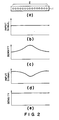
- FIG 2 there is shown an example of a multi-element head 1 provided with a plurality of recording elements 2. It is assumed that when the uniform electric signals are supplied to the image recording elements, as shown in Figure 2, (b), the resultant image density is non-uniform as shown by (c). To avoid the non-uniformity, the supplied signals are adjusted as shown by (d), by which a large input is supplied to the image recording element providing the low density, and a small input is supplied to the image recording element providing the high density. By doing so, the resultant record is as shown by (e).
- the dot sizes are changed in accordance with the inputs.
- the driving voltage or the width of the driving voltage pulse applied to each of the piezoelectric element is changed in accordance with the input signal.
- the driving voltage or the pulse width applied to the heater is changed in accordance with the input signal.
- the adjustment of the input signal is no longer proper.
- the density distribution may change due to deposition of adjacent the ink outlet nozzle and/or due to foreign matter deposited externally.
- the image density distribution may change due to the deterioration or change of the heater elements.
- the initial input adjustment is not effective to correct the changing density non-uniformity. In some cases, the initial adjustment makes the situation worse.
- a recording apparatus comprising a recording head having plural recording elements to record an image in accordance with input image data, detecting means for detecting density non-uniformity of the recording elements at predetermined timing and adjusting means for adjusting driving signals applied to the recording head on the basis of a result of detection by said detecting means.
- the adverse affect due to the change with use or time in the respective recording elements can be minimized.
- FIG. 1 is a block diagram illustrating a major portion of an image recording apparatus according to an embodiment of the present invention.
- Reference numeral 21 designates a given image signal.
- the apparatus comprises a reader 22 for reading a non-uniformity in the density of the record, which comprises CCD elements or photodiode elements, for example, and a driving circuit for the CCD or the photodiode to produce an output 23.
- the apparatus further comprises a CPU 24 for controlling the entire apparatus, a RAM 25 for the density non-uniformity correction for producing a correction signal 26 and a correction table 27 for producing a corrected image signal 28, a binary coding circuit 29 for producing a binary coded signal 30 and an ink jet, for example, head 31 having 256 nozzles as the recording elements.
- the input signal 21 is converted by the density non-uniformity correction table 23 so as to correct the image non-uniformity of the multi-element head 31.
- the correction selecting signal 26 (6 bits are enough) produced by the density correcting RAM 25, a proper one of the correcting lines is selected.
- the input signal correction operation is as follows.
- a correcting line having a small inclination is selected, whereas when the picture element signal is supplied to a nozzle having a property of providing a relatively small dot size, a correcting line having a large inclination is selected.
- the size of the dot, that is, the printed image density is detected on the basis of detection of the density for each of the nozzles by the reader 22.
- the data for the correcting RAM 25 are produced in accordance with the property of the non-uniformity of the head, and the determination is made as to which correcting line is to be selected from the 61 lines.
- the correcting line for each of the nozzles that is, the level of the correcting signal 26 for each of the nozzles is stored.
- the corrected signal 28 corrected by the correcting RAM 25 and the correcting table 27 is binary-coded by the binary coding circuit 29 of a dither process type or error dilusion process type, and is supplied to the multi-element head 31, and then, the image forming operation is performed.
- the number of dots printed by the high density nozzle is small, whereas the number of dots by the low density nozzle is large, as a result of the correction.
- the density non-uniformity of the multi-element head is corrected.
- the data of the correcting RAM are not fixed. Rather, the leader 22 leads the density non-uniformity of the multi-element head actually used, and the RAM can be rewritten in accordance with an output of the leader 22.
- the rewriting operation is as follows. First, the selection is made to the line having the inclination of 1.0 in the correcting table, that is, the no correction state is established. Subsequently, the same input signals 21 are supplied to all the nozzles to actually print by the multi-element head 31.
- the print (sample print) is read by the leader 22 to detect the density non-uniformity of the multi-head 31.
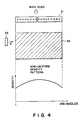
- an output print 42 By actuating all the nozzles of the multi-element 31, an output print 42 can be provided.
- the output image 42 is scanned by CCD elements 43 constituting the leader 22 while moving the CCD elements 43 in the direction A.
- the output of the CCD elements 43 are converted to digital image density signals by an unshown density converter, by which the density non-uniformity pattern as shown at the bottom of Figure 4 is produced.
- the CPU 24 calculates the differences or ratios between the density by the nozzles from the non-uniformity pattern detected and a predetermined density level. On the basis of the calculation, a datum representing which correction table is to be selected for each of the nozzles is written in the correcting RAM 25.
- the correcting operation is carried out for each of predetermined period of time or when a number of prints produced, for example. As a result, even if the density non-uniformity pattern changes, the correction can follow the change, and therefore, the output image is always good.
- the correcting operation may be performed periodically by the user of the recording apparatus, or by a service man.
- a selector button for instructing the printing for the correction may be provided.
- the reader 22 may be a reader for particularly determining the density non-uniformity as described in the foregoing. However, when the present invention is used for a digital copying machine, an original reader can be thereof can be used for this purpose.
- the structure becomes simple, and in addition, the reading non-uniformity of the original reader can be prevented.
- FIG. 5 is a block diagram showing the control system.
- the same reference numerals as in Figure 1 are assigned to the corresponding elements, and the detailed description thereof are omitted for simplicity.
- Figure 6 is a flow chart illustrating the data rewriting operation in this embodiment.
- the program for executing the operation shown in the flow chart is stored in an unshown ROM in the CPU 24.
- the number counter 51 counts the number of prints, and each time the number of prints reaches a predetermined number, it supplies to the CPU 24 a data rewriting signal 55.
- the CPU 24 discriminates whether the data rewrite starting signal 55 is received or not at step S61. If not, a step S68 is executed to perform the normal printing operation.
- a step S62 is carried out to rewrite at first the current RAM 25 data in the data without correction. And then, a uniform test pattern signals having a proper duty level is produced, and when a selector 53 is operated, the test pattern signals 54 are selected as the input signal.
- the test pattern is printed by the multi-element head 31, at step S63.
- the printed pattern is read by the reader 22 at step S64 to detect the non-uniformity on the printed pattern.
- the density correction data is calculated using the pattern, at step S65.
- the calculated data are written in the correcting RAM 25 at step S66.
- the operation of the test pattern generator is stopped, and the selector 53 is operated to select the image signal 21. This is the end of the rewriting operation for the density non-uniformity (step S67).
- the multi-element head 31 and the reader 22 are integral, so that the printing of the test pattern and the reading thereof are carried out substantially simultaneously.
- designated by a reference numeral 31 is multi-element head; 71, a CCD element; 72, the carriage.
- the multi-element head and the CCD element are both mounted on the carriage 72, so that the CCD element scans the print in the direction D.
- the multi-element head 31 prints the test pattern, during which the print by the multi-element 31 to read the printed pattern by the CCD element 71.
- the CCD element 71 includes a number of reading element 73, so that the density non-uniformity pattern can be determined by one scan. In this embodiment, the series of operations are carried out automatically, and therefore, the user or the service man is not required to manipulate the apparatus to print the test pattern and read the printed pattern.
- the automatic correction is started on the basis of the number of prints, but this is not limiting.
- a timer may be employed in place of the number counter, and the non-uniformity detection and the rewriting of the correction data are carried out for each predetermined period of time. By doing so, it can be avoided that the density non-uniformity is changed because the apparatus is rest for a long period of time, although the number of prints is small.
- a timer is employed to detect the rest period of the machine.
- the detection of the density non-uniformity and the rewriting of the correction data can be performed when the rest of the apparatus continues for a predetermined period of time, or they are carried out at the first recording operation after the rest period exceeding the predetermined period.
- the correcting operation can be effected each time the main switches actuated.
- the third embodiment is a modification of the first and second embodiments.
- the tone of the image is provided by binary coding process (dither process or an error diluting process) in other words, the number of output dots from each of the nozzle is changed when the entire image is seen.
- the pulse width of the driving pulse applied to each of the nozzle is changed, by which the amount of ink ejected through the nozzle is corrected.
- Figure 8 is a block diagram for the correcting operation.
- the same reference numerals as in Figure 1 are assigned to the elements having the corresponding functions, and the detailed description thereof is omitted for simplicity.
- the image signal corrected by the density non-uniformity correcting table 27 is supplied to the driving circuit 75.
- the driving circuit 76 produces a driving pulse 6 having a pulse width corresponding to the corrected image signal 28, and drives the multi-nozzle head 31.
- the multi-nozzle head 31 is of a piezoelectric element type, for example, so that the amount of ejection can be changed in accordance with the driving pulse width, so that the density non-uniformity can be corrected by changing the quantity of the ejected liquid for each of the nozzles.
- the driving voltage can be changed.
- the function of the driving circuit 75 produces a driving pulse having a voltage level in accordance with the corrected signal 28.
- the present invention is applicable to a printer in which the input image is a binary coded image as in a wordprocessor a personal computer or the like.
- the present invention is applicable to a so-called bubble jet printer in which a bubble is formed by a heater in the nozzle, and the ink is ejected by the pressure resulting from the formation of the bubble.
- the operators manipulation can be minimized by detecting the timing at which the correction is to be effected, and by automatically correcting the density non-uniformity correction.
- the detecting means for detecting the density non-uniformity may effects its operation when the main switch of the printer is actuated, each time a predetermined number of prints are produced or each time a predetermined period of time elapses.
- the present invention covers the case wherein the density non-uniformity is detected other than when the apparatus is dispatched from a manufacturing plant.
- the present invention is applicable to any apparatus wherein the recording operation is performed by scanningly moving a printing head having a plurality of image recording elements arranged. Therefore, the multi-element head may be a full-multi-element head having the length covering the image formation width or may be a semi-full-multi-element head of serious scan type.
- the adjusting means for adjusting the driving signal applied to the recording head may adjust the image signal before the binary coding process as described hereinbefore or may adjust the signal after binary-coded.
- the adjusting timing is detected, and the density non-uniformity can be automatically corrected, and therefore, the operator is not required to perform additional manipulation.
- the good recording performance can be maintained even if the density non-uniformity of the printing head occurs due to the elapse of time.
Landscapes
- Engineering & Computer Science (AREA)
- Multimedia (AREA)
- Signal Processing (AREA)
- Ink Jet (AREA)
- Particle Formation And Scattering Control In Inkjet Printers (AREA)
- Accessory Devices And Overall Control Thereof (AREA)
- Fax Reproducing Arrangements (AREA)
- Electronic Switches (AREA)
Applications Claiming Priority (2)
| Application Number | Priority Date | Filing Date | Title |
|---|---|---|---|
| JP107744/89 | 1989-04-28 | ||
| JP1107744A JP2854318B2 (ja) | 1989-04-28 | 1989-04-28 | 画像記録装置 |
Publications (3)
| Publication Number | Publication Date |
|---|---|
| EP0399668A2 true EP0399668A2 (fr) | 1990-11-28 |
| EP0399668A3 EP0399668A3 (fr) | 1991-09-11 |
| EP0399668B1 EP0399668B1 (fr) | 1996-01-03 |
Family
ID=14466860
Family Applications (1)
| Application Number | Title | Priority Date | Filing Date |
|---|---|---|---|
| EP90304607A Expired - Lifetime EP0399668B1 (fr) | 1989-04-28 | 1990-04-27 | Appareil d'enregistrement d'image |
Country Status (4)
| Country | Link |
|---|---|
| US (2) | US6045210A (fr) |
| EP (1) | EP0399668B1 (fr) |
| JP (1) | JP2854318B2 (fr) |
| DE (1) | DE69024531T2 (fr) |
Cited By (8)
| Publication number | Priority date | Publication date | Assignee | Title |
|---|---|---|---|---|
| GB2243265A (en) * | 1990-03-29 | 1991-10-23 | Dowty Maritime Ltd | Thermal recording apparatus |
| EP0461759A3 (en) * | 1990-05-11 | 1992-05-20 | Canon Kabushiki Kaisha | Recording apparatus for performing recording using recording head |
| EP0527610A3 (en) * | 1991-08-09 | 1993-07-14 | Canon Kabushiki Kaisha | Recording apparatus |
| EP0532248A3 (en) * | 1991-09-11 | 1993-10-06 | Canon Kabushiki Kaisha | Method for correcting density uneveness for a recording head and an image formation apparatus provided with such a method |
| EP0822703A3 (fr) * | 1996-07-31 | 1998-11-11 | Fuji Photo Film Co., Ltd. | Appareil pour l'enregistrement d'images |
| US6000776A (en) * | 1990-05-11 | 1999-12-14 | Canon Kabushiki Kaisha | Apparatus and method for regulating image density |
| EP0922585A3 (fr) * | 1997-12-08 | 2000-03-15 | Fuji Photo Film Co., Ltd. | Procédé de correction d'irrégularité de densité et dispositif d'enregistrement d'image utilisant ce procédé |
| EP3202579A4 (fr) * | 2014-09-29 | 2018-05-30 | Citizen Watch Co., Ltd. | Imprimante à transfert thermique et procédé d'impression utilisant celle-ci |
Families Citing this family (32)
| Publication number | Priority date | Publication date | Assignee | Title |
|---|---|---|---|---|
| JP3313952B2 (ja) * | 1995-09-14 | 2002-08-12 | キヤノン株式会社 | インクジェット記録装置 |
| KR100238593B1 (ko) * | 1997-12-19 | 2000-01-15 | 윤종용 | 인쇄 품질 개선 방법 |
| JP4244405B2 (ja) * | 1998-07-09 | 2009-03-25 | セイコーエプソン株式会社 | 印刷装置および印刷方法並びに記録媒体 |
| JP2000037936A (ja) * | 1998-07-21 | 2000-02-08 | Canon Inc | プリント位置合わせ方法およびプリント装置 |
| JP4530438B2 (ja) * | 1998-08-11 | 2010-08-25 | オリンパス株式会社 | 画像形成装置 |
| JP2000307865A (ja) * | 1999-04-19 | 2000-11-02 | Canon Inc | 情報処理装置、記録装置、情報処理方法、および記録方法 |
| US6478401B1 (en) | 2001-07-06 | 2002-11-12 | Lexmark International, Inc. | Method for determining vertical misalignment between printer print heads |
| US6626513B2 (en) | 2001-07-18 | 2003-09-30 | Lexmark International, Inc. | Ink detection circuit and sensor for an ink jet printer |
| US7085695B2 (en) * | 2002-03-22 | 2006-08-01 | Seiko Epson Corporation | Slipping contact line model and the mass-conservative level set implementation for ink-jet simulation |
| JP2003285518A (ja) * | 2002-03-28 | 2003-10-07 | Olympus Optical Co Ltd | 画像記録装置 |
| US6779862B2 (en) * | 2002-09-12 | 2004-08-24 | Hewlett-Packard Development, L.P. | System and method of providing power to a print head |
| US7237151B2 (en) * | 2002-12-17 | 2007-06-26 | Texas Instruments Incorporated | Apparatus and method for trace stream identification of a processor reset |
| US7254523B2 (en) * | 2003-03-14 | 2007-08-07 | Seiko Epson Corporation | Selectively reduced bi-cubic interpolation for ink-jet simulations on quadrilateral grids |
| US7117138B2 (en) * | 2003-03-14 | 2006-10-03 | Seiko Epson Corporation | Coupled quadrilateral grid level set scheme for piezoelectric ink-jet simulation |
| US7391525B2 (en) * | 2003-03-14 | 2008-06-24 | Lexmark International, Inc. | Methods and systems to calibrate media indexing errors in a printing device |
| JP4099584B2 (ja) * | 2003-08-14 | 2008-06-11 | ソニー株式会社 | 液体吐出装置及び液体吐出調整方法 |
| US7251591B2 (en) * | 2003-08-29 | 2007-07-31 | Seiko Epson Corporation | Consistent back pressure for piezoelectric ink-jet simulation |
| US20050243117A1 (en) * | 2004-04-28 | 2005-11-03 | Jiun-Der Yu | Divergence filters on quadrilateral grids for ink-jet simulations |
| US7349833B2 (en) * | 2004-10-01 | 2008-03-25 | Seiko Epson Corporation | 2D central difference level set projection method for ink-jet simulations |
| US7623254B2 (en) * | 2004-10-28 | 2009-11-24 | Xerox Corporation | Systems and methods for detecting inkjet defects |
| US7921001B2 (en) * | 2005-08-17 | 2011-04-05 | Seiko Epson Corporation | Coupled algorithms on quadrilateral grids for generalized axi-symmetric viscoelastic fluid flows |
| US20070136042A1 (en) * | 2005-12-09 | 2007-06-14 | Jiun-Der Yu | Quadrilateral grid extension of central difference scheme for ink-jet simulations |
| US20070239413A1 (en) * | 2006-04-06 | 2007-10-11 | Jiun-Der Yu | Local/local and mixed local/global interpolations with switch logic |
| US7536285B2 (en) * | 2006-08-14 | 2009-05-19 | Seiko Epson Corporation | Odd times refined quadrilateral mesh for level set |
| JP5139876B2 (ja) | 2008-04-25 | 2013-02-06 | キヤノン株式会社 | 画像形成装置及び画像形成方法 |
| JP5139877B2 (ja) | 2008-04-25 | 2013-02-06 | キヤノン株式会社 | 画像形成装置及び画像形成方法 |
| US8428922B2 (en) * | 2010-02-05 | 2013-04-23 | Seiko Epson Corporation | Finite difference level set projection method on multi-staged quadrilateral grids |
| JP5593829B2 (ja) * | 2010-05-18 | 2014-09-24 | セイコーエプソン株式会社 | 印刷装置の印刷濃度を補正する方法および印刷装置 |
| JP5625531B2 (ja) | 2010-06-22 | 2014-11-19 | セイコーエプソン株式会社 | 印刷装置および印刷方法 |
| JP6299403B2 (ja) * | 2014-05-09 | 2018-03-28 | 株式会社リコー | 画像形成装置、画像形成システムおよびプログラム |
| JP6739936B2 (ja) * | 2015-12-25 | 2020-08-12 | 東芝テック株式会社 | サーマルプリンタ |
| JP2017132045A (ja) * | 2016-01-25 | 2017-08-03 | セイコーエプソン株式会社 | 印刷装置および印刷方法 |
Family Cites Families (21)
| Publication number | Priority date | Publication date | Assignee | Title |
|---|---|---|---|---|
| US3657707A (en) * | 1969-03-17 | 1972-04-18 | Precision Instr Co | Laser recording system with both surface defect and data error checking |
| JPS5342031A (en) * | 1976-09-28 | 1978-04-17 | Ricoh Co Ltd | Ink injector |
| US4463359A (en) | 1979-04-02 | 1984-07-31 | Canon Kabushiki Kaisha | Droplet generating method and apparatus thereof |
| US4449052A (en) * | 1981-11-30 | 1984-05-15 | International Business Machines Corporation | Method of printing and detecting optimum bar code test patterns |
| JPS58143356A (ja) * | 1982-02-19 | 1983-08-25 | Canon Inc | 光プリンタ |
| US4574293A (en) * | 1983-05-23 | 1986-03-04 | Fuji Xerox Co., Ltd. | Compensation for heat accumulation in a thermal head |
| US4739415A (en) * | 1984-05-01 | 1988-04-19 | Canon Kabushiki Kaisha | Image handling system capable of varying the size of a recorded image |
| JPS60250971A (ja) * | 1984-05-29 | 1985-12-11 | Erumu:Kk | カセツト式プリンタヘツド |
| JPS618365A (ja) * | 1984-06-22 | 1986-01-16 | Fuji Xerox Co Ltd | 転写型感熱記録装置 |
| JPS6232068A (ja) * | 1985-08-02 | 1987-02-12 | Minolta Camera Co Ltd | インクジエツト記録装置 |
| DE3633239A1 (de) * | 1985-10-01 | 1987-04-16 | Canon Kk | Verfahren zum betrieb einer tintenstrahl-aufzeichnungsvorrichtung und tintenstrahl-aufzeichnungsvorrichtung |
| US4853768A (en) * | 1985-12-26 | 1989-08-01 | Canon Kabushiki Kaisha | Color image processing apparatus with linear masking circuit having coefficients which vary in accordance with the levels of color component signals |
| US4751377A (en) * | 1985-12-27 | 1988-06-14 | Fuji Photo Film Co., Ltd. | Light beam scanning recording apparatus and method of correcting intensity of image to be recorded thereby |
| JP2612259B2 (ja) * | 1986-08-25 | 1997-05-21 | キヤノン株式会社 | 画像記録装置および画像記録方法 |
| JPH0738685B2 (ja) * | 1986-11-10 | 1995-04-26 | キヤノン株式会社 | カラ−画像記録装置 |
| JP2607490B2 (ja) * | 1986-12-09 | 1997-05-07 | キヤノン株式会社 | 画像形成装置の画質制御方法 |
| US4897672A (en) * | 1987-07-02 | 1990-01-30 | Fujitsu Limited | Method and apparatus for detecting and compensating light emission from an LED array |
| JPS6463171A (en) * | 1987-09-02 | 1989-03-09 | Victor Company Of Japan | Thermal transfer printer |
| EP0317268B1 (fr) * | 1987-11-16 | 1997-07-23 | Canon Kabushiki Kaisha | Appareil d'enregistrement d'images |
| JPH0782542B2 (ja) * | 1988-01-29 | 1995-09-06 | 株式会社スキャンテクノロジー | 印字検査方法、印字検査装置および印刷物自動振分けシステム |
| US4827279A (en) * | 1988-06-16 | 1989-05-02 | Eastman Kodak Company | Process for correcting across-the-head nonuniformity in thermal printers |
-
1989
- 1989-04-28 JP JP1107744A patent/JP2854318B2/ja not_active Expired - Fee Related
-
1990
- 1990-04-27 DE DE69024531T patent/DE69024531T2/de not_active Expired - Fee Related
- 1990-04-27 EP EP90304607A patent/EP0399668B1/fr not_active Expired - Lifetime
-
1997
- 1997-06-19 US US08/878,584 patent/US6045210A/en not_active Expired - Fee Related
-
1999
- 1999-12-07 US US09/457,081 patent/US6179402B1/en not_active Expired - Fee Related
Cited By (18)
| Publication number | Priority date | Publication date | Assignee | Title |
|---|---|---|---|---|
| GB2243265A (en) * | 1990-03-29 | 1991-10-23 | Dowty Maritime Ltd | Thermal recording apparatus |
| US6000776A (en) * | 1990-05-11 | 1999-12-14 | Canon Kabushiki Kaisha | Apparatus and method for regulating image density |
| EP0461759A3 (en) * | 1990-05-11 | 1992-05-20 | Canon Kabushiki Kaisha | Recording apparatus for performing recording using recording head |
| US5353052A (en) * | 1990-05-11 | 1994-10-04 | Canon Kabushiki Kaisha | Apparatus for producing unevenness correction data |
| EP0663296A1 (fr) * | 1990-05-11 | 1995-07-19 | Canon Kabushiki Kaisha | Appareil d'enregistrement avec lecteur de configuration de test |
| EP0667241A1 (fr) * | 1990-05-11 | 1995-08-16 | Canon Kabushiki Kaisha | Appareil d'enregistrement avec lecteur de configuration de test |
| US6247780B1 (en) | 1991-08-09 | 2001-06-19 | Canon Kabushiki Kaisha | Shading correction processing for an image forming apparatus |
| EP0955768A3 (fr) * | 1991-08-09 | 2000-03-01 | Canon Kabushiki Kaisha | Appareil d'enregistrement |
| US5712666A (en) * | 1991-08-09 | 1998-01-27 | Canon Kabushiki Kaisha | Recording apparatus |
| EP0527610A3 (en) * | 1991-08-09 | 1993-07-14 | Canon Kabushiki Kaisha | Recording apparatus |
| US5946006A (en) * | 1991-09-11 | 1999-08-31 | Canon Kabushiki Kaisha | Method for correcting density unevenness for a recording head and an image formation apparatus provided with such a method |
| US5528270A (en) * | 1991-09-11 | 1996-06-18 | Canon Kabushiki Kaisha | Method for correcting density unevenness for a recording head and an image formation apparatus provided with such a method |
| EP0532248A3 (en) * | 1991-09-11 | 1993-10-06 | Canon Kabushiki Kaisha | Method for correcting density uneveness for a recording head and an image formation apparatus provided with such a method |
| EP0822703A3 (fr) * | 1996-07-31 | 1998-11-11 | Fuji Photo Film Co., Ltd. | Appareil pour l'enregistrement d'images |
| US5973712A (en) * | 1996-07-31 | 1999-10-26 | Fuji Photo Film Co., Ltd. | Image recording apparatus |
| EP0922585A3 (fr) * | 1997-12-08 | 2000-03-15 | Fuji Photo Film Co., Ltd. | Procédé de correction d'irrégularité de densité et dispositif d'enregistrement d'image utilisant ce procédé |
| US6313857B1 (en) | 1997-12-08 | 2001-11-06 | Fuji Photo Film Co., Ltd. | Method for correcting density irregularity and image recording apparatus using the method |
| EP3202579A4 (fr) * | 2014-09-29 | 2018-05-30 | Citizen Watch Co., Ltd. | Imprimante à transfert thermique et procédé d'impression utilisant celle-ci |
Also Published As
| Publication number | Publication date |
|---|---|
| US6179402B1 (en) | 2001-01-30 |
| EP0399668A3 (fr) | 1991-09-11 |
| EP0399668B1 (fr) | 1996-01-03 |
| US6045210A (en) | 2000-04-04 |
| JP2854318B2 (ja) | 1999-02-03 |
| DE69024531T2 (de) | 1996-05-30 |
| JPH02286341A (ja) | 1990-11-26 |
| DE69024531D1 (de) | 1996-02-15 |
Similar Documents
| Publication | Publication Date | Title |
|---|---|---|
| EP0399668A2 (fr) | Appareil d'enregistrement d'image | |
| US5285220A (en) | Image recording apparatus with tone correction for individual recording heads | |
| US6203133B1 (en) | Apparatus and method for enhancing image resolution using multi-level data generated by halftone processor | |
| US5189521A (en) | Image forming apparatus and method for correction image density non-uniformity by reading a test pattern recorded by the apparatus | |
| US5956052A (en) | Image forming apparatus with means for correcting image density non-uniformity | |
| US5539434A (en) | Ink jet recording apparatus and method therefor | |
| US6419341B1 (en) | Method and apparatus for detecting the discharge status of inkjet printheads | |
| EP0456449B1 (fr) | Appareil d'enregistrement d'images et méthode pour la correction d'images | |
| EP0782095B1 (fr) | Imprimante à jet d'encre et méthode de contrôle | |
| EP1288002B1 (fr) | Procédé et appareil pour optimiser des volumes de gouttelettes séparés pour imprimantes multipoints à jet d'encre | |
| US6322186B1 (en) | Image processing method and apparatus, and printing method and apparatus | |
| JP2906400B2 (ja) | インクジェットプリンタ | |
| US7088471B2 (en) | Density correction method and printing apparatus employing the same | |
| US20080158281A1 (en) | Image forming apparatus and control method thereof | |
| EP0517544B1 (fr) | Appareil et procédé d'enregistrement à jet d'encre | |
| US6126264A (en) | Apparatus and method for recording color images with increased image uniformity | |
| JPH11157058A (ja) | プリンタドライバ、画像形成装置及びその制御方法 | |
| US7021734B2 (en) | Inkjet printer and printing system thereof and method of compensating for deteriorated nozzle | |
| EP0593283B1 (fr) | Méthode d'impression d'image et dispositif associé | |
| US20020075278A1 (en) | Image processing apparatus, print control apparatus, method of image processing, and recording medium | |
| EP0552909B1 (fr) | Dispositif de reproduction d'images | |
| US5539442A (en) | Wax transfer type thermal printing method and apparatus | |
| JP2738776B2 (ja) | 画像形成装置 | |
| JPH07323613A (ja) | 画像形成方法とその装置 | |
| JPH05201053A (ja) | 記録装置 |
Legal Events
| Date | Code | Title | Description |
|---|---|---|---|
| PUAI | Public reference made under article 153(3) epc to a published international application that has entered the european phase |
Free format text: ORIGINAL CODE: 0009012 |
|
| AK | Designated contracting states |
Kind code of ref document: A2 Designated state(s): DE FR GB IT |
|
| 17P | Request for examination filed |
Effective date: 19901231 |
|
| PUAL | Search report despatched |
Free format text: ORIGINAL CODE: 0009013 |
|
| AK | Designated contracting states |
Kind code of ref document: A3 Designated state(s): DE FR GB IT |
|
| 17Q | First examination report despatched |
Effective date: 19930322 |
|
| GRAA | (expected) grant |
Free format text: ORIGINAL CODE: 0009210 |
|
| AK | Designated contracting states |
Kind code of ref document: B1 Designated state(s): DE FR GB IT |
|
| REF | Corresponds to: |
Ref document number: 69024531 Country of ref document: DE Date of ref document: 19960215 |
|
| ITF | It: translation for a ep patent filed | ||
| ET | Fr: translation filed | ||
| PLBE | No opposition filed within time limit |
Free format text: ORIGINAL CODE: 0009261 |
|
| STAA | Information on the status of an ep patent application or granted ep patent |
Free format text: STATUS: NO OPPOSITION FILED WITHIN TIME LIMIT |
|
| 26N | No opposition filed | ||
| REG | Reference to a national code |
Ref country code: GB Ref legal event code: IF02 |
|
| PGFP | Annual fee paid to national office [announced via postgrant information from national office to epo] |
Ref country code: DE Payment date: 20080430 Year of fee payment: 19 |
|
| PGFP | Annual fee paid to national office [announced via postgrant information from national office to epo] |
Ref country code: IT Payment date: 20080422 Year of fee payment: 19 |
|
| PGFP | Annual fee paid to national office [announced via postgrant information from national office to epo] |
Ref country code: FR Payment date: 20080331 Year of fee payment: 19 |
|
| PGFP | Annual fee paid to national office [announced via postgrant information from national office to epo] |
Ref country code: GB Payment date: 20080424 Year of fee payment: 19 |
|
| GBPC | Gb: european patent ceased through non-payment of renewal fee |
Effective date: 20090427 |
|
| REG | Reference to a national code |
Ref country code: FR Ref legal event code: ST Effective date: 20091231 |
|
| PG25 | Lapsed in a contracting state [announced via postgrant information from national office to epo] |
Ref country code: DE Free format text: LAPSE BECAUSE OF NON-PAYMENT OF DUE FEES Effective date: 20091103 |
|
| PG25 | Lapsed in a contracting state [announced via postgrant information from national office to epo] |
Ref country code: FR Free format text: LAPSE BECAUSE OF NON-PAYMENT OF DUE FEES Effective date: 20091222 Ref country code: GB Free format text: LAPSE BECAUSE OF NON-PAYMENT OF DUE FEES Effective date: 20090427 |
|
| PG25 | Lapsed in a contracting state [announced via postgrant information from national office to epo] |
Ref country code: IT Free format text: LAPSE BECAUSE OF NON-PAYMENT OF DUE FEES Effective date: 20090427 |