EP0399672A1 - Bodenvernagelung - Google Patents
Bodenvernagelung Download PDFInfo
- Publication number
- EP0399672A1 EP0399672A1 EP90304634A EP90304634A EP0399672A1 EP 0399672 A1 EP0399672 A1 EP 0399672A1 EP 90304634 A EP90304634 A EP 90304634A EP 90304634 A EP90304634 A EP 90304634A EP 0399672 A1 EP0399672 A1 EP 0399672A1
- Authority
- EP
- European Patent Office
- Prior art keywords
- ground
- barrel
- sabot
- launcher
- nail
- Prior art date
- Legal status (The legal status is an assumption and is not a legal conclusion. Google has not performed a legal analysis and makes no representation as to the accuracy of the status listed.)
- Granted
Links
- 239000002689 soil Substances 0.000 title claims abstract description 99
- 238000010304 firing Methods 0.000 claims description 54
- 238000000034 method Methods 0.000 claims description 39
- 238000009412 basement excavation Methods 0.000 claims description 24
- 238000005253 cladding Methods 0.000 claims description 18
- 230000015572 biosynthetic process Effects 0.000 claims description 10
- 238000005755 formation reaction Methods 0.000 claims description 10
- 238000005728 strengthening Methods 0.000 claims description 10
- 230000003014 reinforcing effect Effects 0.000 claims description 7
- 239000011440 grout Substances 0.000 claims description 4
- 239000011347 resin Substances 0.000 claims description 4
- 229920005989 resin Polymers 0.000 claims description 4
- 238000003491 array Methods 0.000 claims description 2
- 230000008878 coupling Effects 0.000 claims 1
- 238000010168 coupling process Methods 0.000 claims 1
- 238000005859 coupling reaction Methods 0.000 claims 1
- 230000035515 penetration Effects 0.000 abstract description 30
- 239000012634 fragment Substances 0.000 description 11
- 239000000463 material Substances 0.000 description 7
- 229920003023 plastic Polymers 0.000 description 6
- 239000004033 plastic Substances 0.000 description 6
- 238000005452 bending Methods 0.000 description 4
- 239000007787 solid Substances 0.000 description 4
- 229910000831 Steel Inorganic materials 0.000 description 3
- 230000001133 acceleration Effects 0.000 description 3
- 239000010959 steel Substances 0.000 description 3
- 230000006835 compression Effects 0.000 description 2
- 238000007906 compression Methods 0.000 description 2
- 238000005553 drilling Methods 0.000 description 2
- 230000000694 effects Effects 0.000 description 2
- 230000000717 retained effect Effects 0.000 description 2
- 238000007789 sealing Methods 0.000 description 2
- RLLPVAHGXHCWKJ-IEBWSBKVSA-N (3-phenoxyphenyl)methyl (1s,3s)-3-(2,2-dichloroethenyl)-2,2-dimethylcyclopropane-1-carboxylate Chemical compound CC1(C)[C@H](C=C(Cl)Cl)[C@@H]1C(=O)OCC1=CC=CC(OC=2C=CC=CC=2)=C1 RLLPVAHGXHCWKJ-IEBWSBKVSA-N 0.000 description 1
- 239000002390 adhesive tape Substances 0.000 description 1
- 239000004411 aluminium Substances 0.000 description 1
- 229910052782 aluminium Inorganic materials 0.000 description 1
- XAGFODPZIPBFFR-UHFFFAOYSA-N aluminium Chemical compound [Al] XAGFODPZIPBFFR-UHFFFAOYSA-N 0.000 description 1
- 238000004458 analytical method Methods 0.000 description 1
- 238000010276 construction Methods 0.000 description 1
- 238000007796 conventional method Methods 0.000 description 1
- 230000003116 impacting effect Effects 0.000 description 1
- 229910052751 metal Inorganic materials 0.000 description 1
- 239000002184 metal Substances 0.000 description 1
- 150000002739 metals Chemical class 0.000 description 1
- 238000000926 separation method Methods 0.000 description 1
- 230000003584 silencer Effects 0.000 description 1
- 239000004575 stone Substances 0.000 description 1
- 238000003466 welding Methods 0.000 description 1
Images



Classifications
-
- E—FIXED CONSTRUCTIONS
- E02—HYDRAULIC ENGINEERING; FOUNDATIONS; SOIL SHIFTING
- E02D—FOUNDATIONS; EXCAVATIONS; EMBANKMENTS; UNDERGROUND OR UNDERWATER STRUCTURES
- E02D5/00—Bulkheads, piles, or other structural elements specially adapted to foundation engineering
- E02D5/74—Means for anchoring structural elements or bulkheads
- E02D5/80—Ground anchors
- E02D5/806—Ground anchors involving use of explosives
-
- E—FIXED CONSTRUCTIONS
- E02—HYDRAULIC ENGINEERING; FOUNDATIONS; SOIL SHIFTING
- E02D—FOUNDATIONS; EXCAVATIONS; EMBANKMENTS; UNDERGROUND OR UNDERWATER STRUCTURES
- E02D17/00—Excavations; Bordering of excavations; Making embankments
- E02D17/20—Securing of slopes or inclines
- E02D17/207—Securing of slopes or inclines with means incorporating sheet piles or piles
-
- E—FIXED CONSTRUCTIONS
- E02—HYDRAULIC ENGINEERING; FOUNDATIONS; SOIL SHIFTING
- E02D—FOUNDATIONS; EXCAVATIONS; EMBANKMENTS; UNDERGROUND OR UNDERWATER STRUCTURES
- E02D3/00—Improving or preserving soil or rock, e.g. preserving permafrost soil
- E02D3/02—Improving by compacting
- E02D3/08—Improving by compacting by inserting stones or lost bodies, e.g. compaction piles
-
- E—FIXED CONSTRUCTIONS
- E02—HYDRAULIC ENGINEERING; FOUNDATIONS; SOIL SHIFTING
- E02D—FOUNDATIONS; EXCAVATIONS; EMBANKMENTS; UNDERGROUND OR UNDERWATER STRUCTURES
- E02D5/00—Bulkheads, piles, or other structural elements specially adapted to foundation engineering
- E02D5/74—Means for anchoring structural elements or bulkheads
- E02D5/80—Ground anchors
-
- E—FIXED CONSTRUCTIONS
- E02—HYDRAULIC ENGINEERING; FOUNDATIONS; SOIL SHIFTING
- E02D—FOUNDATIONS; EXCAVATIONS; EMBANKMENTS; UNDERGROUND OR UNDERWATER STRUCTURES
- E02D7/00—Methods or apparatus for placing sheet pile bulkheads, piles, mouldpipes, or other moulds
-
- E—FIXED CONSTRUCTIONS
- E02—HYDRAULIC ENGINEERING; FOUNDATIONS; SOIL SHIFTING
- E02D—FOUNDATIONS; EXCAVATIONS; EMBANKMENTS; UNDERGROUND OR UNDERWATER STRUCTURES
- E02D7/00—Methods or apparatus for placing sheet pile bulkheads, piles, mouldpipes, or other moulds
- E02D7/02—Placing by driving
- E02D7/06—Power-driven drivers
- E02D7/12—Drivers with explosion chambers
Definitions
- This invention relates to soil nailing and in particular to a method and apparatus for placing a soil nail in the ground. It is known to provide ground strengthening by driving elongate reinforcing members known as soil nails into the ground in an array in order to improve the bulk properties of the ground.
- GB-1580142 for example discloses the use of solid rods or tubes of 3 to 15 metres length arranged in a grid distributed over soil to be stabilized.
- EP-0239258 discloses the use of pickets fired from a launcher with sufficient momentum to penetrate and become embedded in the ground to provide a ground strengthening array.
- the present invention also seeks to provide a method of strengthening ground adjacent to an excavation where it may be difficult or inconvenient to deploy a soil nail launcher within the excavation itself.
- a method of soil nailing in which a soil nail is placed in the ground by driving a first elongate tubular member into the ground, driving a second elongate member into the ground through a bore defined by the first member such that the second member is guided by the first member into a position in which it forms an extension thereto and wherein the second member is fired from a launcher with sufficient momentum to enter the bore and travel to its extending position.
- An advantage of such a method is that the penetration depth of the soil nail may thereby be extended in a convenient and efficient manner while avoiding the problem of handling excessive lengths of reinforcing members.
- the first member is also driven into the ground by being fired from a launcher with sufficient momentum to enable the member to penetrate and become embedded in the ground.
- Members which are placed in the ground in this manner result in minimal disturbance to the surrounding soil compared with conventional methods of drilling or hammering soil nails into position.
- the second member may be tubular thereby extending the bore and one or more further elongate members may be driven into the ground by being fired from a launcher through the extended bore to form one or more further extensions respectively.
- the depth of penetration of the soil nail may thereby be extended in further stages to the desired depth.
- the members comprising a soil nail may be coupled together by means of a grout or resin joint such that the assembled nail can withstand more readily shear forces and both tensile and compressive loads.
- a reinforcing member may be located within the bore to provide additional strength.
- the members may be fired from a launcher having a tubular barrel through which the member is fired and which is positioned relative to the ground surface such that the travel of the member between the open end of the barrel and the ground surface is no more than one half the length of the member to thereby resist buckling and/or deflection of the member.
- the barrel thereby serves as a tubular guide to resist bowing of the member which tends to occur on impact with the ground particularly where a glancing blow is made against a stone or other hard object. Since the bowing amplitude is a maximum at the mid-point of the member the guiding effect of the barrel is most effective if the mid-point is still within the barrel at the moment of impact with the ground surface.
- the barrel also serves to guide the member to resist deflection at an angle from the initial flight path. Guidance during the initial stages of penetration is particularly important since the subsequent trajectory of the member within the ground generally follows the initial trajectory established on penetration.
- the member is a loose fit in the launcher barrel and is provided with a sabot which guides the member coaxially in the barrel during firing.
- Members of different diameter may thereby fired using the same launcher barrel by providing a suitably dimensioned sabot.
- the member may be fired from the launcher by gas pressure acting on the sabot.
- the sabot may conveniently be initially located adjacent the forward end of the member and slidable to a position at the rearward end such that the sabot provides a radial enlargement of the member which arrests the travel of the first member after the member has penetrated the ground to a predetermined extent.
- the second and any further members may similarly be provided with sabots but of a type which fragment on leaving the barrel and are discarded prior to entry of the member into the bore.
- the launcher includes a tubular baffle projecting coaxially from the barrel and having alignment means engageable with the sabot of the previously fired first member to thereby align the barrel axis with the bore prior to firing the second and/or further members.
- apparatus for use in soil nailing comprising an elongate member, a launcher for firing the member into the ground, a barrel of the launcher coaxially receiving the member in a loaded position thereof, an annular sabot mounted on the member in sliding contact with the barrel, the member having a first stop means limiting movement of the sabot relative to the member towards a forward end of the member beyond a first position and second stop means limiting movement of the sabot relative to the member towards a rear end of the member beyond a second position whereby during firing of the launcher the sabot in its first position guides the member within the barrel and is movable upon engagement with the ground to its second position to constitute a radial enlargement of the member which limits the depth to which the member penetrates the ground.
- An advantage of such apparatus is that the depth of penetration can be readily controlled and this is particularly important in the absence of any surface cladding.
- the launcher has a breech defining a chamber communicating with the barrel, the member being locatable in a loaded position in the launcher so as to extend through the chamber in coaxial alignment with the barrel and projecting rearwardly of the chamber through an aperture defined by the breech, and wherein the launcher includes means admitting compressed gas to the chamber on firing whereby the pressurised gas acts on the sabot to drive the member through the barrel.
- the sabot and the seal are connected by a frangible link which may for example be a plurality of resilient straps which are bowed such that the seal and the sabot are urged apart such that they are maintained in their respective position prior to firing of the launcher.
- a frangible link which may for example be a plurality of resilient straps which are bowed such that the seal and the sabot are urged apart such that they are maintained in their respective position prior to firing of the launcher.
- the second stop means comprises a radially projecting formation at the rear end of the member over which the seal cannot pass such that on being fired the seal engages the formation.
- the radially projecting formation comprises a plurality of circumferentially spaced ribs.
- the first stop means comprises an annular shoulder formed at the forward end of the member.
- the sabot may then include a segmented collar tapering in the forward direction with respect to the member into engagement with the shoulder.
- a method of soil nailing in which a soil nail is placed in the ground by being fired from a barrel of a launcher, the method including the steps of loading the nail into the barrel with the nail being a loose fit in the barrel, providing the nail with a sabot which is a sliding fit in the barrel, supporting the barrel such that a forward end of the barrel is spaced from the surface of the ground into which the nail is to be fired, admitting pressurised gas to the barrel to apply an accelerating force to the sabot so as to drive the sabot and with it the nail towards the forward end of the barrel, allowing the nail to travel towards the ground surface such that the sabot exits from the barrel thereby discontinuing the accelerating force and allowing the nail to thereafter continue travelling to penetrate and become embedded in the ground under its own momentum.
- An advantage of such a method is that the removal of the accelerating force prior to impact with the ground avoids placing the nail under axial compressive loading which would otherwise occur if for example the nail continued to be pushed into the ground by a force applied to the rear of the nail. Axial compressive loading would tend to bend and possibly buckle the nail thereby reducing the accuracy with which the nail could be placed in the ground.
- the launcher includes a breech defining an aperture through which a rearward portion of the nail projects prior to being fired and preferably the sabot is connected to the nail adjacent a forward end of the nail during firing.
- apparatus for use in soil nailing comprising a barrel receiving in use a soil nail, support means supporting the barrel such that a forward end of the barrel is spaced from the surface of the ground, the soil nail being a loose fit in the barrel and being provided with a sabot which is slidable in the barrel, the barrel having a rearward end provided with a breech defining a firing chamber closed by the sabot, and firing means operable to admit pressurised gas to the chamber so as to apply an accelerating force to the sabot whereby in use the soil nail is accelerated towards the ground surface by the accelerating force until the sabot exits the barrel, the soil nail thereafter travelling under its own momentum to penetrate and become embedded in the ground.
- the apparatus includes guide means located rearwardly of the barrel and maintaining a rearward portion of the nail in coaxial alignment with the barrel.
- the support means may comprise an articulated arm mounted on a vehicle.
- the apparatus may include a generally cylindrical baffle of greater internal diameter than the barrel and extending in use between the forward end of the barrel and the ground surface.
- the baffle may include a bellows portion.
- apparatus for use in ground strengthening to resist shear failure in ground adjoining an excavation comprising rail means for spanning the excavation, a launcher for firing soil nails, support means for pivotally supporting the launcher on the rail means such that soil nails can be fired through side walls of the excavation into the adjoining ground and translating means for moving the rail means in a direction generally at right angles to the span of the rail means to deploy the launcher at successive locations along the excavation.
- a launcher 1 is shown in its loaded condition in which a first elongate tubular member 2 is located in the launcher ready for firing.
- the launcher 1 comprises a barrel 3 communicating with a chamber 4 defined by a breech 5.
- a forward end 6 of the member 2 is received within an annular sabot 7 of a plastics material which is slidably received in the barrel 3 adjacent to the chamber 4.
- the first member 2 extends through the chamber 4 and projects rearwardly of the launcher 1 through an aperture 9 formed in the breech 5 in axial alignment with the barrel 3.
- An annular breech seal 10 of a plastics material provides sealing between the member 2 and the breech 5 at the aperture 9.
- the first member 2 is of 6 metres length of which 5 metres projects rearwardly of the launcher.
- a gas inlet tube 11 is connected to the chamber 4 for the admission of compressed gas.
- a baffle 12 of larger diameter than the barrel 3 forms an axial projection of the barrel extending into contact with the surface 13 of a body of ground 14.
- the sequence of events on firing the launcher will be described with reference to later Figures but results in the first member 2 being embedded in the ground 14 to an extent such that the sabot 7 is located at the surface 13 as shown in Figure 2.
- the baffle 12 includes a locating ring 16 which is a snug fit around the sabot 7 such that the launcher 1 is then aligned with the previously fired first member 2. In this position a bore 17 defined by the first member 2 is coaxially in alignment with the barrel 3 and hence in alignment with a second member 18 loaded in the launcher as shown in Figure 2.
- the second member 18 is similarly provided with a breech seal 25 forming a seal in the aperture 9 of the breech 5 although the dimensions of the seal 25 are different to those of seal 10 since the diameter of the second member 18 is less than that of the first member 2 in order to facilitate penetration of the second member into the bore 17.
- the second member 18 has a collar 26 adjacent to but spaced from its rear end 27 which constitutes a radial enlargement dimensioned such that it will pass through the breech aperture 9 and will pass through the bore 17 but will not pass through the opening defined by the truncated tip 19 of the first member 2.
- the tip 19 thereby acts as a stop which arrests the second member 18 by engagement with the collar 26.
- the collar 26 is arrested by contact with the tapered tip 19 of the first member 2 since it is too large to pass through the opening 28 defined by the truncated tip.
- the rear end 27 of the second member 18 includes a threaded portion 29 engageable with a reinforcing member 30 shown in chain dot in Figure 5 which optionally may be inserted within the bore 17 to provide additional strength.
- the bore 17 is filled with grout or resin 31 adjacent to the tip 19 to form a joint 32 between the first and second members which is resistant to shear forces and to both tension and compression forces applied along the soil nail 33 constituted by the combined first and second members.
- the collar 26 is deliberately spaced from the rear end 27 of the second member 18 in order to provide adequate bonding surfaces.
- the cap 21 is removed from the tip 19 on impact by the second member 18 during travel through the bore 17 and is therefore not shown in Figure 4.
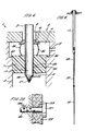
- the sabot 7 associated with the first member 2 is shown to be connected to the forward end 6 by means of cooperating circumferential ribs 34 and grooves 35 formed on the first member 2 and the sabot 7 respectively.
- the ribs and grooves 34 and 35 are ramped to permit movement of the sabot 7 relative to the first member 2 only in a direction towards the rear end 8 of the member.
- the sabot 7 and the breech seal 10 are connected by four circumferentially spaced thin straps 36 which are formed of a resilient plastics material and are bowed to exert a separating force between the breech seal 10 and the sabot 7.
- the breech seal and sabot are thereby held in position prior to firing.
- the straps also serve to maintain the breech seal 10 in position during handling of the first member 2.
- the straps 36 are formed so as to have a weak point adjacent to the junction between each strap with a breech seal 10.
- the launcher is then reloaded with the second member 18 together with its sabot 23 and breech seal 25 as shown in Figure 2.
- the launcher is aligned by locating the locating ring 16 of the baffle 12 over the sabot 7.
- the launcher is then fired by admitting compressed gas to the chamber 4 resulting in gas pressure being applied to the sabot 23 and downward acceleration of the second member 18.
- An extended soil nail 33 as shown in Figure 4 is then provided.
- An array of such nails embedded in the soil will enhance the bulk properties of the ground.
- the nails will be inserted in positions such that the nails intersect a critical slip surface at which the ground is expected to fall.
- ground surface has been shown as horizontal in the above Figures the method may similarly be used in strengthening ground having inclined surfaces or vertical surface where for example a wall of earth is to be reinforced.
- the nails may be fired through apertures formed in the surface cladding or may be fired directly through the cladding.
- first member 2 may be placed in the soil without use of the launcher 1 using conventional drilling, hammering or vibration techniques.
- the second member 18 may then be fired using the launcher provided a suitably dimensioned location ring 16 is used.
- the second member 18 may be replaced by a further hollow member (not shown) of structure generally similar to that of the first member 2 referred to above but having a reduced outer diameter sufficient to be accommodated within the bore 17 of the first member 2.
- Such a modified second member 38 as shown in Figure 8 will form an extension to the bore 17 by providing an additional bore section 39 through which a further member 40 may be fired using the launcher 2.
- the further member 40 may be a solid rod or may again be modified to be tubular to thereby extend the bore and accommodate a further member fired from the launcher (not shown).
- the resulting soil nail may thereby comprise any number of members which are telescopically jointed in accordance with the above method.
- FIG 9 an elongate member 50 is shown in its loaded position in a launcher 1.
- the member 50 may be of any required length but in this example is 6 metres in length and made of steel.
- the member 50 has a conical tip 51 formed integrally with the member which is recessed immediately behind the tip to define the shoulder 52.
- a frusto-conical portion 53 of the member 50 extends between the shoulder 52 and an elongate cylindrical portion 54 which extends through the chamber 4 and projects rearwardly of the breech 5.
- a rear end 55 of the member is crimped to form a plurality of circumferentially spaced axially extending ribs 56 which progressively project radially to form a tapered enlargement 57 at the rear end 55.
- the launcher 1 has a breech 5 defining a chamber 4 communicating with a barrel 3 and the breech is provided with an aperture 9 in axial alignment with the barrel 3 and through which the member 50 extends rearwardly of the breech.
- the member 50 is a loose fit within the barrel 3 and carries a sabot 58 in the form of a collet fitting snugly on the forward end of the cylindrical portion 54 and dimensioned such that the sabot is a sliding fit within the barrel 3.
- the sabot 58 has a rear end 59 projecting into the chamber 4 and four radially extending lugs 60 project from the sabot into the chamber which is formed with a greater diameter than that of the barrel 3. The sabot 58 is thereby restrained prior to firing from movement along the barrel by the lugs 60.
- An annular breech seal 61 is mounted coaxially on the cylindrical portion 54 of the member 50 and is of stepped diameter such that it projects partially into the aperture 9 formed in the breech 5.
- the breech seal 61 is dimensioned to be a sliding fit on the cylindrical portion 54 of the member 50.
- Four circumferentially spaced straps 36 connect the seal 61 with the sabot 58 and are dimensioned such that in the loaded position of the member 50 the straps are bowed and possess sufficient stiffness to exert a separating force between the seal and the sabot. The seal and sabot are thereby retained in their desired positions before firing.
- the straps 36 are made sufficiently thin such that they are frangible on firing to permit separation of the sabot 58 and the seal 61 and are provided with a weak point adjacent to the point of connection with the seal so that on firing the straps remain attached to the sabot as shown in Figure 13.
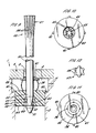
- the sabot 58 is generally cylindrical having a forward face 62 having a central recess 63.
- An annular segmented truncated cone portion 64 projects forwardly within the recess 63 into contact with the shoulder 52 to thereby resist movement of the sabot relative to the member 50 in a direction towards its forward end.
- the cone portion 64 is segmented by slots 65 formed radially and extending longitudinally of the member.
- the relative dimensions of the recess 63 and the cone portion 64 are such that the cylindrical portion 54 can be accommodated within the cone portion by radially outward deflection of the segmented portion such that the segments 65 are accommodated within the recess 63.
- the member 50 can thereby be driven through the sabot by downward movement of the member if the sabot 58 is held stationary but movement in the upward direction is prevented by abutment between the shoulder 52 and the cone portion 64.
- cone portion 64 and cooperating features of the member 50 constitute stop means permitting relative movement in one direction only.
- the launcher 1 includes a baffle 12 which forms an extension to the barrel 3 of enlarged diameter as shown in Figure 13.
- the baffle 12 is placed in contact with the surface 13 of a body of ground 14 at the required location and the launcher is fired by admitting compressed gas to the chamber 4 through the gas inlet tube 11.
- the gas pressure contained within the chamber 4 exerts on the sabot 58 a downward force resulting in acceleration of the sabot and with it the member 50 which is constrained to move with the sabot by the stop means 66.
- Figure 13 shows the position of the sabot 58 shortly after it begins to move downwardly within the barrel.
- Gas pressure within the chamber 4 presses the breech seal 61 into sealing engagement with the breech 5 and the relative movement between the sabot 58 and the seal results in breakage of the straps 36 which continue to be attached to the sabot.
- the seal 61 is formed of a material sufficiently strong to withstand the resultant radial pressure exerted by the enlargement 57 so that the member 50 is arrested. Some further penetration into the ground of the sabot 58 at this instant will occur but generally this travel will be less than the thickness of the sabot.
- the penetration of the soil nail placed by firing from the launcher may thereby be accurately controlled.
- the member 50 in the example shown in Figures 9 to 16 is a solid steel rod but may alternatively be tubular with the conical tip 51 being formed as a separate element connected by welding or otherwise to the cylindrical portion of the member.
- the first stop means may alternatively comprise cooperating ribs and grooves 34 and 35 as shown in Figure 6 which are ramped to permit movement of the sabot relative to the member only in a direction towards the rear end.
- a sabot permits members of different diameter to be accommodated within a launcher of a given barrel size simply by changing the dimensions of the sabot and breech seal.
- the arrangement of a launcher in which the bulk of the member projects rearwardly of the breech allows the launcher of a given barrel length to be used with members of greatly varying length.
- a further advantage of the above apparatus is that the gas pressure admitted to the chamber need not be closely controlled in order to match a required penetration depth since it is sufficient to provide a level of gas pressure which will ensure penetration for all applications and rely on the sabot to arrest the member at the required depth of penetration.
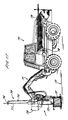
- FIG 17 shows a vehicle 70 suitable for deploying a launcher 1 in soil nailing applications where the ground surface is horizontal, vertical or inclined to the horizontal.
- the vehicle 70 includes an articulated arm 71 allowing the launcher 1 to be oriented as required.
- the launcher 1 in Figure 17 is seen to include a baffle 12 which is shown in contact with a horizontal ground surface 13.
- the launcher barrel (not shown) is shrouded in a jacket 72 with a further shroud 73 surrounding the breech (not shown) in order to lessen the effects of noise on firing.
- a guide 74 projects rearwardly of the launcher 1 and consists of a guide arm 75 and guide ring 76 supported by the guide arm in a position such that a soil nail 77 loaded in the launcher 1 projects rearwardly of the breech and is supported within the guide ring 76.
- the guide 74 ensures that the soil nail 77 is in coaxial alignment with the barrel prior to and during the initial stages of the launch thereby reducing the likelihood of bending and possible buckling of the soil nail during firing.
- the vehicle 70 includes a rack 78 containing a supply of further soil nails 79 of different lengths for future use.
- Figure 18 shows schematically how the launcher 1 might be deployed to fire soil nails 77 into a vertical ground surface 13 in order to stabilise a body of ground 14 against failure at a critical failure surface 80.
- the arm 71 is articulated to a position in which the launcher 1 aims the soil nail 77 at an angle such that it lies approximately at right angles to the critical failure surface.
- the embedded position 77 a of the soil nail 77 after firing is shown in broken lines in Figure 18.
- the embedded soil nail 77 a extends on either side of the critical failure surface 80 so as to prevent relative ground movement on opposite sides of the critical failure surface.
- the launcher 1 is used to fire an array of similar nails 77 into the ground 14 such that collectively the array of soil nails provides ground strengthening and improved resistance to shear failure.
- the nail 77 is received in a sabot 81 of a type which fragments on leaving the barrel 82 and fragments of the sabot are retained within a baffle 83 which encloses a generally cylindrical space 84 between the barrel and the ground surface 13.
- the baffle 83 also contains any flying debris created on impact of the nail 77 with the ground surface 13 in addition to reducing noise created during firing.
- the baffle 83 includes a cylindrical portion 85 which is connected to the barrel 82 and a bellows portion 86 which extends between the cylindrical portion and a disc 87 which is maintained in contact with the ground surface 13.
- the bellows portion 86 is sufficiently flexible to accommodate the launcher being deployed at angles other than 90° relative to the ground surface 13.
- the bellows portion 86 is however sufficiently stiff to ensure that flying debris created within the space 84 remains trapped during firing.
- Figure 19 shows schematically the way in which a sabot 81 can be preformed with cuts 88 and 89 which ensure that the sabot fragments on leaving the launcher barrel.
- the sabot 81 has a rear surface 90 which during firing is exposed to pressurised gas.
- the sabot 81 has cuts 88 and 89 which meet in a diametric line 91 and divide the sabot into three portions 92, 93 and 94.
- the cuts 88, 89 are orthogonal to one another and arranged at 45° to the cylindrical axis of the sabot such that a central portion 93 of the sabot has a triangular cross-section and acts as a wedge to force apart side portions 92 and 94 of the sabot when accelerating gas pressure is applied to the rear surface 90.
- the central portion 93 is formed with further cuts (not shown) allowing the central portion to fragment once the side portions 92 and 94 have separated.
- an alternative apparatus 100 includes a number of features in common with apparatus of preceding Figures so that corresponding reference numerals are used where appropriate for corresponding elements.
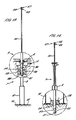
- the apparatus 100 includes a launcher 1 which is shown schematically in three alternative positions 1 a , 1 b and 1 c .
- the launcher 1 is connected to a horizontal rail 101 which is deployed so as to span a trench 102.
- the rail 101 is mounted at each end on wheeled conveyors represented schematically at 103 and 104 respectively.
- ground 108 and 109 adjoining the excavation defining the trench 102 will tend to fail in shear at critical failure surfaces 110.
- the ground can be strengthened against shear failure by emplacing an array of soil nails which intersects the critical failure surface 110 at approximately right angles to the surface, the array being such as to form a grid pattern over the critical failure surface.
- the apparatus 100 enables such an array of soil nails to be emplaced by first deploying the rail at a first location as shown in Figure 20.
- the launcher is deployed at position 1 a in which it is offset to one side of the trench adjacent to the left-hand side wall 105 and so that it directs the soil nail towards the right-hand side wall.
- the launcher is pivotal about a pivot 111 which is slidably movable along the rail 101 and can be clamped at any desired position.
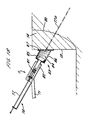
- the launcher 1 a is tilted so as to direct a soil nail 77 at a downwardly directed angle such that on firing it penetrates the corrugated cladding 107 on the right-hand side wall 106 and penetrates the ground 108.
- Penetration of the soil nail 77 is arrested by means of a radial enlargement at the rear end of the soil nail (not shown) the length of nail being selected such that the soil nail crosses the critical failure surface 110 and extends on either side of the surface.
- the launcher 1 a is then tilted to a steeper angle and a second soil nail 77 a is fired into the ground 108.
- the launcher is again reloaded and tilted to an even steeper angle and a further soil nail 77 b fired into the ground.
- the critical failure surface 110 extends upwardly from the toe 112 of the side wall 106 at a progressively increasing angle to the horizontal. As the successive soil nails 77 are fired at progressively steeper angles to the horizontal the tendency for the critical failure surface to change in gradient is compensated at least partially by the change in gradient of successive soil nails such that, to an approximation, the angle of intersection between the soil nail and critical failure surface is maintained at a right angle.
- the launcher is then redeployed to position 1 b at which it is central to the trench and is pointed directly downwards to fire a soil nail 77 c into the ground underlying the trench.
- the launcher 1 is then re-deployed to position 1 c in which it is offset to one side of the trench adjacent to the right-hand side wall 106 and is downwardly directed towards the left-hand side wall 105.
- a corresponding number of soil nails 77 to those fired from location 1 a are again fired at different angles of inclination to the horizontal so as to cross the critical failure surface on the left-hand side of the trench.
- the rail 101 is then moved in a direction at right angles to the rail to a new location and the above process repeated. This procedure is repeated until a suitable array of soil nails 77 extends the full length of the trench 102.
- This procedure can be carried out not only to strengthen the ground adjoining trenches but can be used to support the sides of an excavation for a foundation and to increase the foundation strength as shown schematically in Figure 21.
- a sabot of reinforced strength When firing relatively long soil nails such as 6 metres in length or greater it is desirable to use a sabot of reinforced strength since a greater firing gas pressure will be required. Suitable construction of such a reinforced sabot would be to make use of high strength tensile fibres reinforcing a plastics material or to form the sabot of cast aluminium or other metals.
- FIG. 21 shows a tubular soil nail 120 having a radially enlarged head 121 which on firing is arrested by impact with a surface cladding 122. The nail 120 is fired through a preformed bore 123 in the cladding 122.
- the nail 120 includes a plurality of perforations 124 distributed along its length, these perforations being provided for the purpose of drainage.
- Such a disc or surface cladding will preferably have a preformed hole into which the soil nail is fired and may have elastic putty or the like surrounding the hole such that the radial enlargement of the soil nail compresses the putty on impact.
- the sabot may be connected to the soil nail at positions intermediate the front end and rear end.
- the sabot may for example be located adjacent to but spaced from the front end of the nail where the nail is to be fired through corrugated sheeting or any other type of surface cladding material.
- a non-fragmenting sabot When a non-fragmenting sabot is used as an arresting mechanism it may also be desirable to locate the radial enlargement of the soil nail at a position adjacent to but spaced from the rear end of the nail such that the sabot comes to rest some distance from the rear end. When embedded in the ground this provides for a rear portion of the nail to remain projecting from the ground surface where such projection is desirable.
- sabot used throughout the description and claims should be understood to have its normal meaning of being an attachment to guide a projectile through a bore (in this case the barrel of a launcher). It should be understood however that in certain contexts the element referred to as being a sabot might equally be referred to as being a collet (i.e. a ring or a collar) particularly where the element provides a separate function after having left the barrel so that it is in fact no longer acting as a sabot.
Landscapes
- Engineering & Computer Science (AREA)
- Structural Engineering (AREA)
- Life Sciences & Earth Sciences (AREA)
- Mining & Mineral Resources (AREA)
- General Life Sciences & Earth Sciences (AREA)
- Paleontology (AREA)
- Civil Engineering (AREA)
- General Engineering & Computer Science (AREA)
- Agronomy & Crop Science (AREA)
- Environmental & Geological Engineering (AREA)
- Soil Sciences (AREA)
- Portable Nailing Machines And Staplers (AREA)
- Excavating Of Shafts Or Tunnels (AREA)
- Piles And Underground Anchors (AREA)
- Placing Or Removing Of Piles Or Sheet Piles, Or Accessories Thereof (AREA)
- Investigation Of Foundation Soil And Reinforcement Of Foundation Soil By Compacting Or Drainage (AREA)
- Conveying And Assembling Of Building Elements In Situ (AREA)
Priority Applications (2)
| Application Number | Priority Date | Filing Date | Title |
|---|---|---|---|
| EP92119769A EP0540060B1 (de) | 1989-04-28 | 1990-04-27 | Bodenvernagelung |
| EP92119767A EP0540059B1 (de) | 1989-04-28 | 1990-04-27 | Bodenvernagelung |
Applications Claiming Priority (2)
| Application Number | Priority Date | Filing Date | Title |
|---|---|---|---|
| GB8909837 | 1989-04-28 | ||
| GB898909837A GB8909837D0 (en) | 1989-04-28 | 1989-04-28 | Soil nailing |
Related Child Applications (4)
| Application Number | Title | Priority Date | Filing Date |
|---|---|---|---|
| EP92119769A Division-Into EP0540060B1 (de) | 1989-04-28 | 1990-04-27 | Bodenvernagelung |
| EP92119767.9 Division-Into | 1990-04-27 | ||
| EP92119767A Division-Into EP0540059B1 (de) | 1989-04-28 | 1990-04-27 | Bodenvernagelung |
| EP92119769.5 Division-Into | 1990-04-27 |
Publications (2)
| Publication Number | Publication Date |
|---|---|
| EP0399672A1 true EP0399672A1 (de) | 1990-11-28 |
| EP0399672B1 EP0399672B1 (de) | 1993-11-10 |
Family
ID=10655945
Family Applications (3)
| Application Number | Title | Priority Date | Filing Date |
|---|---|---|---|
| EP90304634A Expired - Lifetime EP0399672B1 (de) | 1989-04-28 | 1990-04-27 | Bodenvernagelung |
| EP92119769A Expired - Lifetime EP0540060B1 (de) | 1989-04-28 | 1990-04-27 | Bodenvernagelung |
| EP92119767A Expired - Lifetime EP0540059B1 (de) | 1989-04-28 | 1990-04-27 | Bodenvernagelung |
Family Applications After (2)
| Application Number | Title | Priority Date | Filing Date |
|---|---|---|---|
| EP92119769A Expired - Lifetime EP0540060B1 (de) | 1989-04-28 | 1990-04-27 | Bodenvernagelung |
| EP92119767A Expired - Lifetime EP0540059B1 (de) | 1989-04-28 | 1990-04-27 | Bodenvernagelung |
Country Status (6)
| Country | Link |
|---|---|
| US (1) | US5044831A (de) |
| EP (3) | EP0399672B1 (de) |
| JP (1) | JP2674861B2 (de) |
| DE (3) | DE69023008T2 (de) |
| ES (3) | ES2078633T3 (de) |
| GB (2) | GB8909837D0 (de) |
Families Citing this family (23)
| Publication number | Priority date | Publication date | Assignee | Title |
|---|---|---|---|---|
| JP3611903B2 (ja) * | 1994-11-11 | 2005-01-19 | 住友商事株式会社 | ソイルネイル用コレット、ソイルネイルおよびその打込装置 |
| US7048471B2 (en) | 2000-04-05 | 2006-05-23 | Maksim Kadiu | Shoring device |
| US6821057B1 (en) | 2000-04-05 | 2004-11-23 | Maksim Kadiu | Magnetic shoring device |
| US6745421B2 (en) | 2002-01-10 | 2004-06-08 | Robert K. Barrett | Abutment with seismic restraints |
| US6742967B1 (en) * | 2002-11-07 | 2004-06-01 | Nelson N. S. Chou | Structure for fastening soil nails to reinforced soil retaining walls |
| US6874975B2 (en) * | 2002-12-09 | 2005-04-05 | Hilfiker Pipe Company | Soil-nail apparatus and method for constructing soil reinforced earthen retaining walls |
| US7056067B2 (en) | 2003-10-03 | 2006-06-06 | Max Kadiu | Trench shoring device |
| US7708502B2 (en) * | 2003-11-17 | 2010-05-04 | Joseph D. Carte | System and method for stabilizing landslides and steep slopes |
| US7226247B2 (en) * | 2003-12-18 | 2007-06-05 | Barrett Robert K | Method and apparatus for creating soil or rock subsurface support |
| US9273442B2 (en) * | 2003-12-18 | 2016-03-01 | R&B Leasing, Llc | Composite self-drilling soil nail and method |
| US7338233B2 (en) * | 2003-12-18 | 2008-03-04 | Barrett Robert K | Soil nail and method of installing a subsurface support |
| US20070172315A1 (en) * | 2003-12-18 | 2007-07-26 | Barrett Robert K | Method and Apparatus for Creating Soil or Rock Subsurface Support |
| US8851801B2 (en) | 2003-12-18 | 2014-10-07 | R&B Leasing, Llc | Self-centralizing soil nail and method of creating subsurface support |
| US6890127B1 (en) | 2003-12-23 | 2005-05-10 | Robert K. Barrett | Subsurface platforms for supporting bridge/culvert constructions |
| US7384217B1 (en) | 2007-03-29 | 2008-06-10 | Barrett Robert K | System and method for soil stabilization of sloping surface |
| US7654775B2 (en) * | 2008-05-09 | 2010-02-02 | R&B Leasing, Llc | Soil nail launcher |
| AU2009243461B1 (en) * | 2009-12-01 | 2011-04-14 | R&B Leasing, Llc | Soil nail launcher |
| US8376661B2 (en) | 2010-05-21 | 2013-02-19 | R&B Leasing, Llc | System and method for increasing roadway width incorporating a reverse oriented retaining wall and soil nail supports |
| CN102505688B (zh) * | 2011-09-26 | 2013-10-30 | 上海市城市建设设计研究总院 | 预制节段桩精确导向施工工艺 |
| CN103835646A (zh) * | 2013-02-18 | 2014-06-04 | 高林 | 一种带有挡板的地钻 |
| JP6830625B2 (ja) * | 2016-03-03 | 2021-02-17 | 日鉄建材株式会社 | 多段式排水パイプの押出治具及び多段式排水パイプの押出方法 |
| KR102010332B1 (ko) * | 2018-08-17 | 2019-08-13 | 씨에스건설 (주) | 앵커 및 앵커체결장치 |
| CN114482034B (zh) * | 2022-02-15 | 2025-05-16 | 宁夏交通建设股份有限公司 | 一种耐腐蚀的预应力混凝土管桩 |
Citations (4)
| Publication number | Priority date | Publication date | Assignee | Title |
|---|---|---|---|---|
| NL7702212A (en) * | 1977-03-02 | 1978-09-05 | Berg A P Ingbureau | Soil sampling probe anchoring equipment - has bar with hinging blades driven into ground with coupling rods |
| FR2447424A1 (fr) * | 1979-01-26 | 1980-08-22 | Travocean Sarl St | Dispositif d'implantation et d'ancrage de pieux sur les fonds sous-marins |
| EP0039654A2 (de) * | 1980-05-05 | 1981-11-11 | TRAVOCEAN Société à Responsabilité Limitée dite | Sprengvorrichtung zum Verankern von Pfählen und ähnlichen Gegenständen im Boden |
| EP0278936A1 (de) * | 1987-02-06 | 1988-08-17 | Bo Andreasson | Verfahren zum Eintreiben von Pfählen |
Family Cites Families (10)
| Publication number | Priority date | Publication date | Assignee | Title |
|---|---|---|---|---|
| US2522685A (en) * | 1945-05-08 | 1950-09-19 | Wadsworth W Mount | Projectile |
| US2512831A (en) * | 1947-02-26 | 1950-06-27 | Holmes Arthur Brannam | Production of concrete piles |
| US3819101A (en) * | 1969-08-01 | 1974-06-25 | Lee Norse Co | Apparatus for setting pins in mine roofs |
| US3802204A (en) * | 1970-04-01 | 1974-04-09 | E Mason | Retaining wall and method for construction of the same |
| US4033419A (en) * | 1973-04-04 | 1977-07-05 | Allied Chemical Corporation | Vibrator and pushing apparatus for driving metal pins in rock faces in mines |
| US4005811A (en) * | 1974-05-30 | 1977-02-01 | Australian Iron & Steel Proprietary Limited | Roof bolt injection mast |
| DE2631745A1 (de) * | 1976-07-15 | 1978-01-26 | Bauer Spezialtiefbau | Verfahren zur bodenvernagelung |
| GB2058182B (en) * | 1979-09-10 | 1983-11-23 | Reynolds A J | Method and apparatus for propelling projectiles |
| US4313695A (en) * | 1980-01-07 | 1982-02-02 | Ingersoll-Rand Company | Earth structure stabilizing method, and a friction rock stabilizer and an axial extension therefor |
| GB8604823D0 (en) * | 1986-02-27 | 1986-04-03 | Cotts Plc Mitchell | Ground strengthening |
-
1989
- 1989-04-28 GB GB898909837A patent/GB8909837D0/en active Pending
-
1990
- 1990-04-27 DE DE69023008T patent/DE69023008T2/de not_active Expired - Fee Related
- 1990-04-27 GB GB9009464A patent/GB2232700B/en not_active Expired - Fee Related
- 1990-04-27 EP EP90304634A patent/EP0399672B1/de not_active Expired - Lifetime
- 1990-04-27 EP EP92119769A patent/EP0540060B1/de not_active Expired - Lifetime
- 1990-04-27 DE DE90304634T patent/DE69004488T2/de not_active Expired - Fee Related
- 1990-04-27 EP EP92119767A patent/EP0540059B1/de not_active Expired - Lifetime
- 1990-04-27 ES ES92119769T patent/ES2078633T3/es not_active Expired - Lifetime
- 1990-04-27 ES ES92119767T patent/ES2074799T3/es not_active Expired - Lifetime
- 1990-04-27 DE DE69021088T patent/DE69021088T2/de not_active Expired - Fee Related
- 1990-04-27 ES ES90304634T patent/ES2045803T3/es not_active Expired - Lifetime
- 1990-04-30 US US07/515,743 patent/US5044831A/en not_active Expired - Lifetime
- 1990-05-01 JP JP2111870A patent/JP2674861B2/ja not_active Expired - Lifetime
Patent Citations (4)
| Publication number | Priority date | Publication date | Assignee | Title |
|---|---|---|---|---|
| NL7702212A (en) * | 1977-03-02 | 1978-09-05 | Berg A P Ingbureau | Soil sampling probe anchoring equipment - has bar with hinging blades driven into ground with coupling rods |
| FR2447424A1 (fr) * | 1979-01-26 | 1980-08-22 | Travocean Sarl St | Dispositif d'implantation et d'ancrage de pieux sur les fonds sous-marins |
| EP0039654A2 (de) * | 1980-05-05 | 1981-11-11 | TRAVOCEAN Société à Responsabilité Limitée dite | Sprengvorrichtung zum Verankern von Pfählen und ähnlichen Gegenständen im Boden |
| EP0278936A1 (de) * | 1987-02-06 | 1988-08-17 | Bo Andreasson | Verfahren zum Eintreiben von Pfählen |
Non-Patent Citations (1)
| Title |
|---|
| TRAVAUX, vol. 11, no. 553, March 1981, pages 76-81; G. VERRIER et al.: "Confortement des remblais ferroviaires une technique particulière: le clouage" * |
Also Published As
| Publication number | Publication date |
|---|---|
| JP2674861B2 (ja) | 1997-11-12 |
| EP0540059B1 (de) | 1995-07-19 |
| GB2232700B (en) | 1993-06-09 |
| ES2078633T3 (es) | 1995-12-16 |
| EP0399672B1 (de) | 1993-11-10 |
| ES2045803T3 (es) | 1994-01-16 |
| EP0540060A1 (de) | 1993-05-05 |
| GB8909837D0 (en) | 1989-06-14 |
| EP0540060B1 (de) | 1995-10-11 |
| DE69004488T2 (de) | 1994-02-24 |
| ES2074799T3 (es) | 1995-09-16 |
| DE69021088T2 (de) | 1996-03-21 |
| DE69021088D1 (de) | 1995-08-24 |
| DE69004488D1 (de) | 1993-12-16 |
| JPH0369718A (ja) | 1991-03-26 |
| EP0540059A1 (de) | 1993-05-05 |
| GB9009464D0 (en) | 1990-06-20 |
| GB2232700A (en) | 1990-12-19 |
| DE69023008T2 (de) | 1996-03-14 |
| US5044831A (en) | 1991-09-03 |
| DE69023008D1 (de) | 1995-11-16 |
Similar Documents
| Publication | Publication Date | Title |
|---|---|---|
| US5044831A (en) | Soil nailing | |
| US5017047A (en) | Soil nailing | |
| US6494139B1 (en) | Hole boring charge assembly | |
| US8104568B2 (en) | Seismic gun assembly for shooting into a bore hole | |
| JPH0674713B2 (ja) | 既設管を新管と敷設替えする方法および装置 | |
| CA2043926C (en) | Adhesive secondary blasting cone | |
| CS216697B2 (en) | Method of blasting the hard material particularly rock and device for executing the said method | |
| US4488487A (en) | Stepped body penetration bomb | |
| US3228153A (en) | Explosive actuated anchor | |
| GB2243391A (en) | Soil nailing | |
| GB2243392A (en) | Soil nailing | |
| US7226247B2 (en) | Method and apparatus for creating soil or rock subsurface support | |
| US4165946A (en) | Method of securing a rock bolt | |
| US5542784A (en) | Method and means for driving pipes into the ground and cartridge used therefor and for subsequent pipe blasting | |
| US5239930A (en) | Hypervelocity sabot | |
| GB2257238A (en) | Telescopic penetrator | |
| US11434695B2 (en) | Projectile drilling systems and methods | |
| GB2157751A (en) | Driven piling system | |
| US2903070A (en) | Apparatus for investigating earth formations | |
| US5913252A (en) | Pyrotechnic tool driving device | |
| JP2670733B2 (ja) | 地中函体の推進ジャッキ | |
| GB2158135A (en) | Improvements relating to method for driving piles | |
| JP3301108B2 (ja) | 万能打込機 | |
| RU2160395C2 (ru) | Пробойник пиромеханический | |
| NZ233873A (en) | Fastener sleeve with collapsable inner column |
Legal Events
| Date | Code | Title | Description |
|---|---|---|---|
| PUAI | Public reference made under article 153(3) epc to a published international application that has entered the european phase |
Free format text: ORIGINAL CODE: 0009012 |
|
| AK | Designated contracting states |
Kind code of ref document: A1 Designated state(s): DE ES FR IT NL |
|
| 17P | Request for examination filed |
Effective date: 19910215 |
|
| 17Q | First examination report despatched |
Effective date: 19920219 |
|
| GRAA | (expected) grant |
Free format text: ORIGINAL CODE: 0009210 |
|
| AK | Designated contracting states |
Kind code of ref document: B1 Designated state(s): DE ES FR IT NL |
|
| XX | Miscellaneous (additional remarks) |
Free format text: TEILANMELDUNG 92119767.9 EINGEREICHT AM 27/04/90. |
|
| ITF | It: translation for a ep patent filed | ||
| REF | Corresponds to: |
Ref document number: 69004488 Country of ref document: DE Date of ref document: 19931216 |
|
| ET | Fr: translation filed | ||
| REG | Reference to a national code |
Ref country code: ES Ref legal event code: FG2A Ref document number: 2045803 Country of ref document: ES Kind code of ref document: T3 |
|
| PLBE | No opposition filed within time limit |
Free format text: ORIGINAL CODE: 0009261 |
|
| STAA | Information on the status of an ep patent application or granted ep patent |
Free format text: STATUS: NO OPPOSITION FILED WITHIN TIME LIMIT |
|
| 26N | No opposition filed | ||
| PGFP | Annual fee paid to national office [announced via postgrant information from national office to epo] |
Ref country code: DE Payment date: 20000414 Year of fee payment: 11 |
|
| PGFP | Annual fee paid to national office [announced via postgrant information from national office to epo] |
Ref country code: NL Payment date: 20000428 Year of fee payment: 11 Ref country code: FR Payment date: 20000428 Year of fee payment: 11 Ref country code: ES Payment date: 20000428 Year of fee payment: 11 |
|
| PG25 | Lapsed in a contracting state [announced via postgrant information from national office to epo] |
Ref country code: ES Free format text: LAPSE BECAUSE OF NON-PAYMENT OF DUE FEES Effective date: 20010428 |
|
| PG25 | Lapsed in a contracting state [announced via postgrant information from national office to epo] |
Ref country code: FR Free format text: THE PATENT HAS BEEN ANNULLED BY A DECISION OF A NATIONAL AUTHORITY Effective date: 20010430 |
|
| PG25 | Lapsed in a contracting state [announced via postgrant information from national office to epo] |
Ref country code: NL Free format text: LAPSE BECAUSE OF NON-PAYMENT OF DUE FEES Effective date: 20011101 |
|
| NLV4 | Nl: lapsed or anulled due to non-payment of the annual fee |
Effective date: 20011101 |
|
| PG25 | Lapsed in a contracting state [announced via postgrant information from national office to epo] |
Ref country code: DE Free format text: LAPSE BECAUSE OF NON-PAYMENT OF DUE FEES Effective date: 20020201 |
|
| REG | Reference to a national code |
Ref country code: FR Ref legal event code: ST |
|
| REG | Reference to a national code |
Ref country code: ES Ref legal event code: FD2A Effective date: 20030203 |
|
| PG25 | Lapsed in a contracting state [announced via postgrant information from national office to epo] |
Ref country code: IT Free format text: LAPSE BECAUSE OF NON-PAYMENT OF DUE FEES;WARNING: LAPSES OF ITALIAN PATENTS WITH EFFECTIVE DATE BEFORE 2007 MAY HAVE OCCURRED AT ANY TIME BEFORE 2007. THE CORRECT EFFECTIVE DATE MAY BE DIFFERENT FROM THE ONE RECORDED. Effective date: 20050427 |