EP0399689B1 - Appareil d'enregistrement avec disque magnéto-optique - Google Patents
Appareil d'enregistrement avec disque magnéto-optique Download PDFInfo
- Publication number
- EP0399689B1 EP0399689B1 EP90304919A EP90304919A EP0399689B1 EP 0399689 B1 EP0399689 B1 EP 0399689B1 EP 90304919 A EP90304919 A EP 90304919A EP 90304919 A EP90304919 A EP 90304919A EP 0399689 B1 EP0399689 B1 EP 0399689B1
- Authority
- EP
- European Patent Office
- Prior art keywords
- magneto
- optical disc
- magnetic head
- optical
- head
- Prior art date
- Legal status (The legal status is an assumption and is not a legal conclusion. Google has not performed a legal analysis and makes no representation as to the accuracy of the status listed.)
- Expired - Lifetime
Links
Images


Classifications
-
- G—PHYSICS
- G11—INFORMATION STORAGE
- G11B—INFORMATION STORAGE BASED ON RELATIVE MOVEMENT BETWEEN RECORD CARRIER AND TRANSDUCER
- G11B11/00—Recording on or reproducing from the same record carrier wherein for these two operations the methods are covered by different main groups of groups G11B3/00 - G11B7/00 or by different subgroups of group G11B9/00; Record carriers therefor
- G11B11/10—Recording on or reproducing from the same record carrier wherein for these two operations the methods are covered by different main groups of groups G11B3/00 - G11B7/00 or by different subgroups of group G11B9/00; Record carriers therefor using recording by magnetic means or other means for magnetisation or demagnetisation of a record carrier, e.g. light induced spin magnetisation; Demagnetisation by thermal or stress means in the presence or not of an orienting magnetic field
-
- G—PHYSICS
- G11—INFORMATION STORAGE
- G11B—INFORMATION STORAGE BASED ON RELATIVE MOVEMENT BETWEEN RECORD CARRIER AND TRANSDUCER
- G11B17/00—Guiding record carriers not specifically of filamentary or web form, or of supports therefor
- G11B17/02—Details
- G11B17/04—Feeding or guiding single record carrier to or from transducer unit
- G11B17/05—Feeding or guiding single record carrier to or from transducer unit specially adapted for discs not contained within cartridges
- G11B17/051—Direct insertion, i.e. without external loading means
-
- G—PHYSICS
- G11—INFORMATION STORAGE
- G11B—INFORMATION STORAGE BASED ON RELATIVE MOVEMENT BETWEEN RECORD CARRIER AND TRANSDUCER
- G11B11/00—Recording on or reproducing from the same record carrier wherein for these two operations the methods are covered by different main groups of groups G11B3/00 - G11B7/00 or by different subgroups of group G11B9/00; Record carriers therefor
- G11B11/10—Recording on or reproducing from the same record carrier wherein for these two operations the methods are covered by different main groups of groups G11B3/00 - G11B7/00 or by different subgroups of group G11B9/00; Record carriers therefor using recording by magnetic means or other means for magnetisation or demagnetisation of a record carrier, e.g. light induced spin magnetisation; Demagnetisation by thermal or stress means in the presence or not of an orienting magnetic field
- G11B11/105—Recording on or reproducing from the same record carrier wherein for these two operations the methods are covered by different main groups of groups G11B3/00 - G11B7/00 or by different subgroups of group G11B9/00; Record carriers therefor using recording by magnetic means or other means for magnetisation or demagnetisation of a record carrier, e.g. light induced spin magnetisation; Demagnetisation by thermal or stress means in the presence or not of an orienting magnetic field using a beam of light or a magnetic field for recording by change of magnetisation and a beam of light for reproducing, i.e. magneto-optical, e.g. light-induced thermomagnetic recording, spin magnetisation recording, Kerr or Faraday effect reproducing
- G11B11/10532—Heads
- G11B11/10534—Heads for recording by magnetising, demagnetising or transfer of magnetisation, by radiation, e.g. for thermomagnetic recording
-
- G—PHYSICS
- G11—INFORMATION STORAGE
- G11B—INFORMATION STORAGE BASED ON RELATIVE MOVEMENT BETWEEN RECORD CARRIER AND TRANSDUCER
- G11B11/00—Recording on or reproducing from the same record carrier wherein for these two operations the methods are covered by different main groups of groups G11B3/00 - G11B7/00 or by different subgroups of group G11B9/00; Record carriers therefor
- G11B11/10—Recording on or reproducing from the same record carrier wherein for these two operations the methods are covered by different main groups of groups G11B3/00 - G11B7/00 or by different subgroups of group G11B9/00; Record carriers therefor using recording by magnetic means or other means for magnetisation or demagnetisation of a record carrier, e.g. light induced spin magnetisation; Demagnetisation by thermal or stress means in the presence or not of an orienting magnetic field
- G11B11/105—Recording on or reproducing from the same record carrier wherein for these two operations the methods are covered by different main groups of groups G11B3/00 - G11B7/00 or by different subgroups of group G11B9/00; Record carriers therefor using recording by magnetic means or other means for magnetisation or demagnetisation of a record carrier, e.g. light induced spin magnetisation; Demagnetisation by thermal or stress means in the presence or not of an orienting magnetic field using a beam of light or a magnetic field for recording by change of magnetisation and a beam of light for reproducing, i.e. magneto-optical, e.g. light-induced thermomagnetic recording, spin magnetisation recording, Kerr or Faraday effect reproducing
- G11B11/1055—Disposition or mounting of transducers relative to record carriers
- G11B11/10556—Disposition or mounting of transducers relative to record carriers with provision for moving or switching or masking the transducers in or out of their operative position
- G11B11/10558—Disposition or mounting of transducers relative to record carriers with provision for moving or switching or masking the transducers in or out of their operative position in view of the loading or unloading of the carrier
-
- G—PHYSICS
- G11—INFORMATION STORAGE
- G11B—INFORMATION STORAGE BASED ON RELATIVE MOVEMENT BETWEEN RECORD CARRIER AND TRANSDUCER
- G11B33/00—Constructional parts, details or accessories not provided for in the other groups of this subclass
- G11B33/02—Cabinets; Cases; Stands; Disposition of apparatus therein or thereon
- G11B33/027—Covers
Definitions
- the invention relates to magneto-optical disc recording apparatus.
- a light beam emitted from a laser light source is irradiated intermittently to a recording film of a magneto-optical disc and a magnetic head is driven while being supplied with a modulated signal based on the information to be recorded, whereby the temperature of the recording film on the magneto-optical disc is locally raised with application of a modulated magnetic field, whose polarity is inverted in conformity with the information, from the magnetic head to the recording film on the magneto-optical disc, so that the perpendicular magnetized film is oriented by the polarity of such modulated magnetic field of the magnetic head and the information is recorded on the magneto-optical disc.
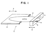
- a magneto-optical disc 2 is placed on a tray 3 as shown in Figure 1.
- the tray 3 is movable between a first position outside an opening in a case (not shown) of the apparatus, i.e. a position where the magneto-optical disc is replaceable, and a second position within the opening in the apparatus case 1, i.e. a position where a recording or reproducing operation can be performed on the magneto-optical disc by an optical head and a magnetic head which will be described later.
- the tray 3 is moved as indicated by arrow a so that the magneto-optical disc 2 can be loaded into or ejected from the apparatus.
- An optical head 4 and a magnetic head 5 are held by a holding member 6 in such a manner as to be retained opposite to each other with the magneto-optical disc 2 interposed therebetween.
- the holding member 6 is movable in the radial direction of the magneto-optical disc 2 as indicated by arrow b , and both the optical head 4 and the magnetic head 5 can be shifted to a desired recording track on the magneto-optical disc when the holding member 6 is moved in the direction of the arrow b by shifting means (not shown).
- the magnetic head 5 used in such magneto-optical disc recording/reproducing apparatus comprises a cylindrical core 8 which is sectionally of E-shape and a coil 9 wound around a centre core element 8A of the core 8 with a predetermined number of turns, as illustrated in Figure 2.
- a modulated magnetic field symmetrical with respect to the central axis of the centre core element 8A is generated between the centre core element 8A and a side core element 8B, so that the desired information can be recorded on the magneto-optical disc 2, more specifically in the recording film on the magneto-optical disc 2, with application of such modulated magnetic field thereto by the magnetic head 5 simultaneously with irradiation of the light beam performed by the optical head 4 from the reverse side with respect to the magnetic field.
- Patent Specification GB-A-2 181 879 discloses magneto-optical recording apparatus wherein a magnetic head comprises an E-shaped magnetic member with a coil wound around a middle arm of the magnetic member.
- a magneto-optical disc recording apparatus comprising an optical head shiftable in a diametrical direction of a magneto-optical disc and capable of irradiating a light beam onto the magneto-optical disc, and a magnetic head disposed to be mutually opposite to the optical head, with the magneto-optical disc interposed therebetween, to apply a magnetic field to the magneto-optical disc while being shifted in the diametrical direction of the magneto-optical disc, the magnetic head comprising an E-shaped core and a coil wound around a centre core element thereof, characterised in that the magnetic head is so formed that the sectional length of the centre core element in one direction extending toward two side core elements is equal to or shorter than the sectional length in the direction orthogonal thereto, and the magnetic head is so disposed that the orthogonal direction is coincident with the diametrical direction of the magneto-optical disc, whereby the intensity of the magnetic field generated by the magnetic head reduces more gradually in the diametrical direction
- magneto-optical disc recording apparatus 10 has a cover 11 which can be manually opened or closed so as to load or replace a magneto-optical disc 2.
- a circular recess 13 for loading a magneto-optical disc is formed at the centre of the upper surface of an apparatus body 12, and a rotary spindle 15 of a spindle motor projects upwardly from the middle of the floor of the recess 13.
- the spindle 15 is furnished with a disc table for centring an optical disc or a magneto-optical disc, and in practice the disc is placed on the disc table.
- the disc table projects through the floor of the recess 13 so as to prevent contact of the magneto-optical disc with the floor of the recess 13.
- a holding mechanism may be disposed at the centre of the disc table to hold the central portion of the magneto-optical disc, or a grip member may be disposed within the cover 11 to grip the magneto-optical disc in a manner so as to be rotatable together with the disc table.
- Hinge means is provided in a rear portion on the upper surface of the apparatus body 12 so as to hold the cover 11 by two lateral edges swingably to the apparatus body 12, whereby the cover 11 can be swung to open or close the recess 13.
- An opening 16 is formed in a rear portion on the upper surface of the apparatus body 12, and a magnetic head 20 and an optical head 22 are mutually interlocked via a shaft 18 positioned above the opening 16.
- bearings 24 and 25 which project from the upper surface of the apparatus body 12, and the two ends of the shaft 18 are held by the bearings 24 and 25.
- a magnetic head support member 30 is pivotally retained by the shaft 18 in a manner to be shiftable in the diametrical direction of the magneto-optical disc or the axial direction of the shaft 18.
- the magnetic head support member 30 is further rendered swingable toward or away from one surface of the magneto-optical disc on the reverse side with respect to irradiation of the light beam from the optical head. That is, the shaft 18 functions as a hinge pin of a hinge mechanism for swinging the magnetic head support member 30 and also as a guide pin for the magnetic head support member 30.
- an optical head support member 31 is attached to the shaft 18 on each side of the magnetic head support member 30, so that the magnetic head support member 30 is actuated by a driving force applied to the optical head support member 31 and is thereby shifted along the shaft 18 in the diametrical direction of the magneto-optical disc through its connection to the optical head support member 31.
- the optical head support member 31 thus retained by the shaft 18 shiftably thereto is also retained pivotally to be shiftable in the diametrical direction of the magneto-optical disc by guide shafts 35 and 36 disposed in the apparatus body 12 in parallel with the shaft 18, and is driven by feed means such as a linear actuator (not shown) so as to be shifted along the guide shafts 35 and 36.
- the magnetic head support member 30 and the optical head support member 31 are mutually connected via the shaft 18 as mentioned, so that when the optical head support member 31 is shifted along the shaft 18 and the guide shafts 35, 36 by the feed means, the magnetic head support member 30 is also shifted in accordance therewith in the diametrical direction of the magneto-optical disc.
- the optical head 22 is mounted on the fore end of the optical head support member 31 and is so set as to be capable of focusing, through an objective lens disposed in the optical head 22, a light beam emitted from a laser light source in the optical head 22 and then irradiating such light beam through a slit 38, which is formed in the recess 13 of the apparatus body 12, to a magneto-optical disc 2 loaded into the apparatus body 12.
- the light beam from the optical head 22 shifted along the guide shafts 35, 36 by the feed means can be positionally displaced in the diametrical direction of the magneto-optical disc 2, so that the light beam can irradiate a desired recording track on the magneto-optical disc 2.
- the optical head support member 31 has a plate-shaped projection 39 in the proximity of the bearing portion of the shaft 18, and a screw 40 is inserted into the projection 39.
- the amount of swing of the magnetic head support member 30 can be changed by adjusting the length of protrusion of such screw 40.
- the magnetic head 20 is disposed at the fore end of the magnetic head support member 10 in a manner to be opposed to the optical head 22.
- the amount of swing of the magnetic head support member 30 is changeable by adjusting the length of protrusion of the screw 40, the distance between the magneto-optical disc 2 and the magnetic head 20 can be adjusted by a simple operation.
- a U-shaped lock member 42 is attached to the fore end of the magnetic head support member 30 on the opposite side thereof to the magnetic head 20, whereby the magnetic head support member 30 can be swung in accordance with the action of opening or closing the cover 11.
- bearings 44 and 45 projecting inward, and a shaft 46 is disposed between the two bearings 44 and 45.
- the shaft 46 is supported substantially in parallel with the shaft 18 while extending through a rectangular space defined by the magnetic head support member 30 and the lock member 42.
- the magnetic head 20 is shifted simply by manually opening or closing the cover 11.
- the conventional magnetic head 5 (shown in Figure 2) is used in such a case, it may become difficult to attain a desired field intensity resulting in a failure in recording the information with certainty.
- the magnetic head 20 is formed as illustrated in Figure 5, so as to expand the magnetic field applicable range in comparison with the known structure.
- a magnetic circuit is formed by a vertically sectionally E-shaped core 50, a centre core element 50A of which is square in horizontal section and has a cylindrical coil 51 wound therearound.
- the intensity of the modulated magnetic field sharply decreases, as graphically shown in Figure 6, in accordance with a recession from the centre core element 50A (denoted by 0) toward two side core elements 50S (i.e. in an x -direction).
- the intensity of the modulated magnetic field only gently decreases as graphically shown in Figure 7, so that the operable range of the magnetic field is expanded by 20 to 30 percent as compared with the conventional magnetic head (shown in Figure 2) where a magnetic field is formed which is symmetrical with respect to the axis of the centre core element 8A.
- the magnetic head 20 is so disposed that the y-direction is coincident with the radial direction of the magneto-optical disc 2 ( i.e. , the direction in which the magnetic head 20 and the optical head 22 are shiftable), whereby desired information can be recorded with certainty despite positional changes of the magnetic head 20 that may be induced by each action of opening or closing the cover 11.
- the illustrated embodiment mentioned shows a magnetic circuit of the magnetic head 20 formed by the E-shaped core 50 including the horizontally square section centre core element 50A.
- the magnetic head may be modified as illustrated in Figure 8, wherein a magnetic circuit is formed by the use of an E-shaped core 60 with a horizontally rectangular section centre core element 60A in which the length in the y-direction is longer than the length in the x-direction.
- the applicable range of the modulated magnetic field can be expanded in the y-direction by an amount corresponding to the increased y-direction length of the centre core element 60A.
- the horizontal sectional shape of the centre core element is not limited to a square or a rectangle alone, and the requisite thereof resides in that the horizontal sectional length of the centre core element in one direction is equal to or longer than the length in another orthogonal direction extending from the centre core element toward the two side core elements.
- the horizontal sectional shape of its centre core element is circular or elliptical.
- the coil 51 wound around the centre core element 50A is cylindrical.
- the coil 51 could be of other shapes, for example it could be any suitable tubular shape, for example with a square or rectangular horizontal section.
- cylindrical coil 51 is shown wound directly around the centre core element 50A in the above embodiment, it could equally be wound around a bobbin disposed on the centre core element.
- a magneto-optical disc 2 is loaded or ejected by manually opening or closing the cover 11.
- the invention is however equally applicable to a disc apparatus of other type where a magneto-optical disc is loaded or ejected by other means, for example by moving a tray.
Claims (1)
- Appareil d'enregistrement sur disque magnéto-optique (10) comprenant une tête optique (22) pouvant se déplacer dans une direction diamétrale d'un disque magnéto-optique et capable de projeter un faisceau lumineux sur le disque magnéto-optique (2), et une tête magnétique (20) disposée de manière à être mutuellement en face de la tête optique (22), le disque magnéto-optique (2) étant interposé entre elles, pour appliquer un champ magnétique au disque magnéto-optique (2) tout en se déplaçant dans la direction diamétrale du disque magnéto-optique (2), la tête magnétique (20) comprenant un noyau en forme de E (50, 60) et une bobine (51) enroulée autour d'un élément de noyau central (50A, 60A) de celui-ci ;
caractérisé en ce que la tête magnétique (20) est formée de telle façon que la longueur en coupe de l'élément de noyau central (50A) dans une première direction (x) s'étendant vers les deux éléments de noyaux latéraux (50S) soit égale ou inférieure à la longueur en coupe dans la direction (y) qui lui est orthogonale, et en ce que la tête magnétique (20) est disposée de telle façon que la direction orthogonale (y) coïncide avec la direction diamétrale du disque magnéto-optique, ce par quoi l'intensité du champ magnétique produit par la tête magnétique (20) diminue plus graduellement dans la direction diamétrale (y) du disque magnéto-optique que dans ladite première direction (x).
Applications Claiming Priority (2)
| Application Number | Priority Date | Filing Date | Title |
|---|---|---|---|
| JP1130679A JPH02308403A (ja) | 1989-05-23 | 1989-05-23 | 光磁気デイスク装置 |
| JP130679/89 | 1989-05-23 |
Publications (3)
| Publication Number | Publication Date |
|---|---|
| EP0399689A2 EP0399689A2 (fr) | 1990-11-28 |
| EP0399689A3 EP0399689A3 (fr) | 1991-01-16 |
| EP0399689B1 true EP0399689B1 (fr) | 1995-04-19 |
Family
ID=15040021
Family Applications (1)
| Application Number | Title | Priority Date | Filing Date |
|---|---|---|---|
| EP90304919A Expired - Lifetime EP0399689B1 (fr) | 1989-05-23 | 1990-05-08 | Appareil d'enregistrement avec disque magnéto-optique |
Country Status (7)
| Country | Link |
|---|---|
| US (1) | US5072431A (fr) |
| EP (1) | EP0399689B1 (fr) |
| JP (1) | JPH02308403A (fr) |
| KR (1) | KR0167768B1 (fr) |
| CA (1) | CA2016559C (fr) |
| DE (1) | DE69018700T2 (fr) |
| MY (1) | MY105747A (fr) |
Families Citing this family (11)
| Publication number | Priority date | Publication date | Assignee | Title |
|---|---|---|---|---|
| DE69228279T2 (de) * | 1991-08-30 | 1999-07-08 | Canon K.K., Tokio/Tokyo | Gerät für magnetooptische Platte mit schwebendem Magnetkopf |
| TW209901B (fr) * | 1992-01-27 | 1993-07-21 | Sony Co Ltd | |
| US5625607A (en) * | 1992-02-13 | 1997-04-29 | Canon Kabushiki Kaisha | Magneto-optical disk apparatus including two magnetic field applying devices, one of which has a substantial ring-shaped core member with a gap in a portion thereof |
| JP3146683B2 (ja) * | 1992-10-14 | 2001-03-19 | ソニー株式会社 | 光磁気ディスク記録再生装置 |
| JP3153947B2 (ja) * | 1993-04-28 | 2001-04-09 | ソニー株式会社 | 磁気ヘッド及び光磁気記録装置 |
| KR960005652B1 (ko) * | 1993-12-17 | 1996-04-30 | 현대전자산업주식회사 | 미니 디스크 플레이어의 바이어스 자계 코일 헤드 구동장치 |
| TW347899U (en) * | 1994-08-31 | 1998-12-11 | Sony Corp | Optical recording/reproducing device |
| US5896255A (en) * | 1995-10-02 | 1999-04-20 | Aris Mardirossian, Inc. | Magnetic disc cartridge and corresponding system/method for limiting coping of software |
| US5636096A (en) * | 1995-10-02 | 1997-06-03 | Aris Mardirossian, Inc. | Magnetic disc cartridge and corresponding system/method for limiting copying of software |
| US8366769B2 (en) | 2000-06-01 | 2013-02-05 | Edwards Lifesciences Corporation | Low-profile, pivotable heart valve sewing ring |
| JP2002367109A (ja) * | 2001-06-08 | 2002-12-20 | Canon Inc | 光磁気記録用磁気ヘッドおよび光磁気記録装置 |
Family Cites Families (10)
| Publication number | Priority date | Publication date | Assignee | Title |
|---|---|---|---|---|
| JPH0664821B2 (ja) * | 1984-12-30 | 1994-08-22 | オリンパス光学工業株式会社 | 記録媒体の装着装置 |
| JPS61284801A (ja) * | 1985-06-10 | 1986-12-15 | Matsushita Electric Ind Co Ltd | 光磁気記録再生装置 |
| US4843600A (en) * | 1985-09-13 | 1989-06-27 | Canon Kabushiki Kaisha | Recording head for magneto-optical information recording apparatus |
| JP2574747B2 (ja) * | 1985-11-20 | 1997-01-22 | 株式会社日立製作所 | 光磁気記録装置 |
| JPH06103549B2 (ja) * | 1986-02-12 | 1994-12-14 | ソニー株式会社 | 光磁気記録装置 |
| JP2609228B2 (ja) * | 1986-04-22 | 1997-05-14 | ソニー株式会社 | 光磁気記録装置 |
| JP2566924B2 (ja) * | 1986-07-14 | 1996-12-25 | キヤノン株式会社 | 光磁気記録装置 |
| JPS6346644A (ja) * | 1986-08-13 | 1988-02-27 | Nec Home Electronics Ltd | 垂直磁気記録再生ヘツド |
| JPS6355704A (ja) * | 1986-08-26 | 1988-03-10 | Olympus Optical Co Ltd | 光磁気記録装置用磁界印加装置 |
| US4984225A (en) * | 1987-03-31 | 1991-01-08 | Kabushiki Kaisha Toshiba | System for applying magnetic field to opto-magnetic memory |
-
1989
- 1989-05-23 JP JP1130679A patent/JPH02308403A/ja active Pending
-
1990
- 1990-04-10 US US07/507,036 patent/US5072431A/en not_active Expired - Lifetime
- 1990-05-07 KR KR1019900006362A patent/KR0167768B1/ko not_active Expired - Fee Related
- 1990-05-08 DE DE69018700T patent/DE69018700T2/de not_active Expired - Lifetime
- 1990-05-08 EP EP90304919A patent/EP0399689B1/fr not_active Expired - Lifetime
- 1990-05-11 CA CA002016559A patent/CA2016559C/fr not_active Expired - Lifetime
- 1990-05-12 MY MYPI90000765A patent/MY105747A/en unknown
Also Published As
| Publication number | Publication date |
|---|---|
| JPH02308403A (ja) | 1990-12-21 |
| DE69018700D1 (de) | 1995-05-24 |
| DE69018700T2 (de) | 1995-08-24 |
| KR0167768B1 (ko) | 1999-03-20 |
| EP0399689A3 (fr) | 1991-01-16 |
| CA2016559C (fr) | 1999-07-27 |
| KR900018943A (ko) | 1990-12-22 |
| CA2016559A1 (fr) | 1990-11-23 |
| EP0399689A2 (fr) | 1990-11-28 |
| MY105747A (en) | 1994-11-30 |
| US5072431A (en) | 1991-12-10 |
Similar Documents
| Publication | Publication Date | Title |
|---|---|---|
| EP0416797B1 (fr) | Appareil de chargement de support d'information en forme de disque | |
| US5072431A (en) | Magneto-optical disk recording apparatus | |
| DE69231192T2 (de) | Plattenaufzeichnungs- und/oder -wiedergabegerät | |
| US5226024A (en) | Disk recording and/or reproducing apparatus | |
| EP0387047B1 (fr) | Appareil d'enregistrement magnéto-optique | |
| EP0104914A1 (fr) | Appareil d'enregistrement et/ou de reproduction pour disques | |
| JPH01292651A (ja) | 光磁気記録装置のバイアス磁界移動装置 | |
| US5247496A (en) | Recording and/or reproducing apparatus for using magneto-optical disc | |
| EP0455158B1 (fr) | Appareil d'enregistrement et de reproduction pour disque magnéto-optique | |
| JPH06131607A (ja) | 光磁気ディスク記録再生装置 | |
| US5594708A (en) | Magnetooptical disc apparatus with magnetic head | |
| JP2940268B2 (ja) | 光磁気ディスク記録再生装置 | |
| US6212157B1 (en) | Apparatus for suppressing warping optical disk and optical disk apparatus | |
| KR100269165B1 (ko) | 광픽업의대물렌즈구동부지지장치 | |
| JP2000353330A (ja) | 対物レンズ駆動装置 | |
| KR950003174B1 (ko) | 광자기 기록장치 | |
| JP3610587B2 (ja) | 記録及び/又は再生装置 | |
| JP2788586B2 (ja) | 光磁気ディスク記録再生装置 | |
| USRE35608E (en) | Recording and/or reproducing apparatus for using magneto-optical disc | |
| JP2586792Y2 (ja) | 光磁気ディスク装置 | |
| JPH04141830A (ja) | 光学ヘッド及びディスク駆動装置 | |
| JP3733623B2 (ja) | 記録媒体ローディング機構 | |
| JPS6262438A (ja) | アクチユエ−タ | |
| JP3421866B2 (ja) | 軸の支持機構及び光ディスク装置。 | |
| JP2001076419A (ja) | ディスク記録再生装置及びディスク駆動機構 |
Legal Events
| Date | Code | Title | Description |
|---|---|---|---|
| PUAI | Public reference made under article 153(3) epc to a published international application that has entered the european phase |
Free format text: ORIGINAL CODE: 0009012 |
|
| AK | Designated contracting states |
Kind code of ref document: A2 Designated state(s): DE FR GB NL |
|
| PUAL | Search report despatched |
Free format text: ORIGINAL CODE: 0009013 |
|
| AK | Designated contracting states |
Kind code of ref document: A3 Designated state(s): DE FR GB NL |
|
| 17P | Request for examination filed |
Effective date: 19910517 |
|
| 17Q | First examination report despatched |
Effective date: 19931215 |
|
| GRAA | (expected) grant |
Free format text: ORIGINAL CODE: 0009210 |
|
| AK | Designated contracting states |
Kind code of ref document: B1 Designated state(s): DE FR GB NL |
|
| REF | Corresponds to: |
Ref document number: 69018700 Country of ref document: DE Date of ref document: 19950524 |
|
| ET | Fr: translation filed | ||
| PLBE | No opposition filed within time limit |
Free format text: ORIGINAL CODE: 0009261 |
|
| STAA | Information on the status of an ep patent application or granted ep patent |
Free format text: STATUS: NO OPPOSITION FILED WITHIN TIME LIMIT |
|
| 26N | No opposition filed | ||
| REG | Reference to a national code |
Ref country code: GB Ref legal event code: IF02 |
|
| PGFP | Annual fee paid to national office [announced via postgrant information from national office to epo] |
Ref country code: NL Payment date: 20090504 Year of fee payment: 20 |
|
| PGFP | Annual fee paid to national office [announced via postgrant information from national office to epo] |
Ref country code: DE Payment date: 20090429 Year of fee payment: 20 |
|
| PGFP | Annual fee paid to national office [announced via postgrant information from national office to epo] |
Ref country code: GB Payment date: 20090506 Year of fee payment: 20 |
|
| REG | Reference to a national code |
Ref country code: FR Ref legal event code: ST Effective date: 20100129 |
|
| PG25 | Lapsed in a contracting state [announced via postgrant information from national office to epo] |
Ref country code: FR Free format text: LAPSE BECAUSE OF NON-PAYMENT OF DUE FEES Effective date: 20090602 |
|
| PGFP | Annual fee paid to national office [announced via postgrant information from national office to epo] |
Ref country code: FR Payment date: 20080514 Year of fee payment: 19 |
|
| REG | Reference to a national code |
Ref country code: NL Ref legal event code: V4 Effective date: 20100508 |
|
| REG | Reference to a national code |
Ref country code: GB Ref legal event code: PE20 Expiry date: 20100507 |
|
| PG25 | Lapsed in a contracting state [announced via postgrant information from national office to epo] |
Ref country code: NL Free format text: LAPSE BECAUSE OF EXPIRATION OF PROTECTION Effective date: 20100508 |
|
| PG25 | Lapsed in a contracting state [announced via postgrant information from national office to epo] |
Ref country code: GB Free format text: LAPSE BECAUSE OF EXPIRATION OF PROTECTION Effective date: 20100507 |
|
| PG25 | Lapsed in a contracting state [announced via postgrant information from national office to epo] |
Ref country code: DE Free format text: LAPSE BECAUSE OF EXPIRATION OF PROTECTION Effective date: 20100508 |