EP0399855A1 - Dispositif de serrage d'un roulement de butée d'embrayage sur un support coulissant - Google Patents
Dispositif de serrage d'un roulement de butée d'embrayage sur un support coulissant Download PDFInfo
- Publication number
- EP0399855A1 EP0399855A1 EP90400799A EP90400799A EP0399855A1 EP 0399855 A1 EP0399855 A1 EP 0399855A1 EP 90400799 A EP90400799 A EP 90400799A EP 90400799 A EP90400799 A EP 90400799A EP 0399855 A1 EP0399855 A1 EP 0399855A1
- Authority
- EP
- European Patent Office
- Prior art keywords
- support
- clip
- bearing
- radial
- clamping
- Prior art date
- Legal status (The legal status is an assumption and is not a legal conclusion. Google has not performed a legal analysis and makes no representation as to the accuracy of the status listed.)
- Ceased
Links
- 238000004080 punching Methods 0.000 claims description 2
- 238000007373 indentation Methods 0.000 abstract 1
- 210000005069 ears Anatomy 0.000 description 2
- 239000002184 metal Substances 0.000 description 2
- 238000003754 machining Methods 0.000 description 1
- 239000000463 material Substances 0.000 description 1
- 238000000465 moulding Methods 0.000 description 1
- 230000000750 progressive effect Effects 0.000 description 1
- 230000000717 retained effect Effects 0.000 description 1
- 229920002994 synthetic fiber Polymers 0.000 description 1
Images


Classifications
-
- F—MECHANICAL ENGINEERING; LIGHTING; HEATING; WEAPONS; BLASTING
- F16—ENGINEERING ELEMENTS AND UNITS; GENERAL MEASURES FOR PRODUCING AND MAINTAINING EFFECTIVE FUNCTIONING OF MACHINES OR INSTALLATIONS; THERMAL INSULATION IN GENERAL
- F16D—COUPLINGS FOR TRANSMITTING ROTATION; CLUTCHES; BRAKES
- F16D23/00—Details of mechanically-actuated clutches not specific for one distinct type
- F16D23/12—Mechanical clutch-actuating mechanisms arranged outside the clutch as such
- F16D23/14—Clutch-actuating sleeves or bearings; Actuating members directly connected to clutch-actuating sleeves or bearings
Definitions
- the invention relates to a device for clamping a thrust bearing on a sliding guide, axially movable in the direction of control of a clutch mechanism.
- the invention relates more particularly to a device for tightening the non-rotating ring of the bearing which gives the ring a certain radial freedom accompanied by an elastic tightening for holding the ring in axial support sliding on its support.
- the publication FR-A-2470898 describes such a device applied to a self-centering stop whose support includes housings for embedding the devices.
- the object of the invention is to remedy the aforementioned drawback and relates more particularly to a new arrangement of the devices for clamping the bearing on its support free of vibrations during the operation of the stop.
- the invention applies more particularly to a declutching stop in which the fixed ring of the bearing is retained against a radial flange of the stop support by means of the clamping device.
- the flange carries a radial slot with converging edges for the reception of a lug formed on the tongue of a staple in contact with said flange.
- the clip has bearing surfaces of a declutching fork so that the sliding support is protected from any wear contact in contact with said fork.
- the support can thus be obtained by molding a plastic material without requiring any specific machining to improve the operation of the stop.
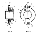
- the clutch bearing represented in FIGS. 1, 2 and 6 essentially comprises a bearing designated by 1 as a whole, with pressed sheet metal rings and angular contact balls, and a support designated by 2 as a whole, on which one fixed rings 3 of the bearing is mounted with a certain radial freedom at 4, and held axially by means of elastic clips 5a, 5b, the other ring 6 of the bearing being free to rotate and having a front surface intended to cooperate with a clutch actuating member, such as a diaphragm not shown.
- the support 2 is intended to be slidably mounted on a guide tube shown in 9 in phantom in Figure 6, and to undergo axial movements on the latter for the purpose of declutching and clutching, controlled by through a fork, the fingers of which are shown in 10 in phantom in FIG. 6.
- the support 2 here in molded synthetic material, has a radial flange 11 the front face of which serves as an axial bearing surface sliding to a flange 12 forming part of the ring 3.
- the flange 11 of the support has at its periphery two opposite ears 13 and on which the two metal clips 5a, 5b are engaged, each clipped onto two retaining lugs 16 and constituting the surfaces of cooperation of the stop with the fork fingers 10.
- Each clip constitutes a clamp as shown in FIGS. 4 and 5 and exerts the clamping force on the flange 11 of the support 2 and on the flange 12 of the fixed ring 3.
- each clip is engaged between the edges of a notch 17 provided on the corresponding ear of the flange 11.
- the collar 11 has on each of its ears 13, a radial slot 18 which opens at the periphery of the collar.
- the converging edges 19 of the slot 18 immobilize a lug 20 carried by a tongue 21 of the clip.
- the lug 20 is advantageously produced by punching the tongue 21 before forming the clamp by folding.
- the arrangement of the slot 19 also allows a radial mounting of the clip and the progressive introduction of the lug 20 between the edges of the slot 18 until a localized lateral contact is obtained between the 'lug 20 and the support 2, sufficient to oppose any unwanted movement of the clip relative to the support 2 or the bearing during operation of the clutch release bearing.
Landscapes
- Engineering & Computer Science (AREA)
- General Engineering & Computer Science (AREA)
- Mechanical Engineering (AREA)
- Mechanical Operated Clutches (AREA)
Abstract
Dispositif de serrage d'un roulement (1) de butée sur un support coulissant (9) guidé, qui comporte une agrafe (5a, 5b) de retenue de la bague (3) fixe du roulement, engagée dans l'échancrure d'une collerette radiale (11) du support (2), caractérisé par le fait que la collerette (11) porte une fente (18) radiale à bords convengents de réception d'un ergot (20) formé sur une languette de l'agrafe en contact avec ladite collerette. 
Description
- L'invention concerne un dispositif de serrage d'un roulement de butée sur un support coulissant guidé, déplaçable axialement dans le sens de commande d'un mécanisme d'embrayage.
- L'invention concerne plus particulièrement un dispositif de serrage de la bague non tournante du roulement qui confère à la bague une certaine liberté radiale accompagnée d'un serrage élastique de maintien de la bague en appui axial glissant sur son support.
- La publication FR-A-2470898 décrit un tel dispositif appliquée à une butée autocentreuse dont le support comporte des logements d'encastrement des dispositifs.
- Ces butées nécessitent un jeu de montage des dispositifs dont la présence occasionne des vibrations consécutives aux déplacements omnidirectionnels du roulement.
- L'invention a pour objet de remédier à l'inconvénient précité et concerne plus particulièrement une disposition nouvelle des dispositifs de serrage du roulement sur son support exempt de vibrations au cours du fonctionnement de la butée.
- L'invention s'applique plus particulièrement à une butée de débrayage dans laquelle la bague fixe du roulement est retenue contre une collerette radiale du support de butée au moyen du dispositif de serrage.
- Selon l'invention, la collerette porte une fente radiale à bords convergents pour la réception d'un ergot formé sur la languette d'une agrafe au contact de ladite collerette.
- Il est en outre prévu que l'agrafe présente des surfaces d'appui d'une fourchette de débrayage de sorte que le support coulissant soit protégé de tout contact d'usure au contact de ladite fourchette. Le support pourra ainsi être obtenu par moulage d'une matière plastique sans nécessiter aucun usinage spécifique à l'amélioration du fonctionnement de la butée.
- D'autres caractéristiques et avantages de l'invention apparaîtront à la lecture de l'exemple de réalisation de celle-ci, décrit en se référant au dessin annexé, dans lequel :
- - la figure 1 est une vue en coupe axiale de la butée portant le dispositif de serrage conforme à l'invention,
- - la figure 2 est une vue de dos de la butée suivant la flèche F de la figure 1,
- - la figure 3 est une vue de dos du support du roulement,
- - les figures 4 et 5 sont des vues en perspective des deux types d'agrafes du dispositif de serrage,
- - la figure 6 est une vue en coupe axiale de la butée montée à coulissement sur un arbre support sous l'action d'une fourchette de commande.
- La butée d'embrayage représentée aux figures 1, 2 et 6 comporte essentiellement un roulement désigné par 1 dans son ensemble, à bagues en tôle emboutie et billes à contact oblique, et un support désigné par 2 dans son ensemble, sur lequel l'une des bagues 3 fixe du roulement est montée avec une certaine liberté radiale en 4, et maintenue axialement par l'intermédiaire d'agrafes élastiques 5a, 5b, l'autre bague 6 du roulement étant libre de tourner et présentant une surface frontale destinée à coopérer avec un organe d'actionnement de l'embrayage, tel qu'un diaphragme non représenté.
- Ainsi qu'il est usuel, le support 2 est destiné à être monté à coulissement sur un tube guide représenté en 9 en trait mixte à la figure 6, et à subir des déplacements axiaux sur ce dernier aux fins de débrayage et embrayage, commandés par l'intermédiaire d'une fourchette dont les doigts sont représentés en 10 en trait mixte à la figure 6.
- Le support 2, ici en matière synthétique moulée, présente une collerette radiale 11 dont la face avant sert de surface d'appui axial glissant à une collerette 12 formant partie de la bague 3. La collerette 11 du support présente à sa périphérie deux oreilles opposées 13 et sur lesquelles sont engagées les deux agrafes métalliques 5a, 5b, clipsées chacune sur deux ergots de retenue 16 et constituant les surfaces de coopération de la butée avec les doigts de fourchette 10.
- Chaque agrafe constitue une pince telle que représentée aux figures 4 et 5 et exerce l'effort de serrage sur la collerette 11 du support 2 et sur la collerette 12 de la bague fixe 3.
- A cet effet, chaque agrafe est engagée entre les bords d'une échancrure 17 prévue sur l'oreille correspondante de la collerette 11.
- Selon l'invention, la collerette 11 possède sur chacune de ses oreilles 13, une fente radiale 18 qui débouche à la périphérie de la collerette.
- Les bords convergents 19 de la fente 18 immobilisent un ergot 20 porté par une languette 21 de l'agrafe. L'ergot 20 est avantageusement réalisé par poinçonnage de la languette 21 avant formation de la pince par pliage.
- L'agencement de la fente 19 autorise, par ailleurs, un montage radial de l'agrafe et l'introduction progressive de l'ergot 20 entre les bords de la fente 18 jusqu'à l'obtention d'un contact latéral localisé entre l'ergot 20 et le support 2, suffisant à s'opposer à tout déplacement indésirable de l'agrafe par rapport au support 2 ou au roulement en cours de fonctionnement de la butée de débrayage.
Claims (3)
1 / Dispositif de serrage d'un roulement (1) de butée sur un support coulissant (2) guidé qui comporte une agrafe (5a, 5b) de retenue de la bague (3) fixe du roulement, engagée dans l'échancrure d'une collerette radiale (11) du support (2), caractérisé par le fait que la collerette (11) porte une fente (18) radiale à bords convergents de réception d'un ergot (2) formé sur la languette (21) d'une agrafe en contact de ladite collerette (11).
2 / Dispositif selon la revendication 1, caractérisé par le fait que l'ergot (20) est réalisé par découpage poinçonnage d'une languette de l'agrafe, et prend appui contre les bords (19) de la fente radiale.
3 / Dispositif selon l'une quelconque des revendications 1 ou 2, caractérisé par le fait que la fente (18) débouche à la périphérie de la collerette radiale du support du roulement dans le but de permettre le montage radial de l'agrafe.
Applications Claiming Priority (2)
| Application Number | Priority Date | Filing Date | Title |
|---|---|---|---|
| FR8905098 | 1989-04-18 | ||
| FR8905098A FR2645929B1 (fr) | 1989-04-18 | 1989-04-18 | Dispositif de serrage d'un roulement de butee sur un support coulissant |
Publications (1)
| Publication Number | Publication Date |
|---|---|
| EP0399855A1 true EP0399855A1 (fr) | 1990-11-28 |
Family
ID=9380830
Family Applications (1)
| Application Number | Title | Priority Date | Filing Date |
|---|---|---|---|
| EP90400799A Ceased EP0399855A1 (fr) | 1989-04-18 | 1990-03-23 | Dispositif de serrage d'un roulement de butée d'embrayage sur un support coulissant |
Country Status (2)
| Country | Link |
|---|---|
| EP (1) | EP0399855A1 (fr) |
| FR (1) | FR2645929B1 (fr) |
Cited By (13)
| Publication number | Priority date | Publication date | Assignee | Title |
|---|---|---|---|---|
| DE19631186A1 (de) * | 1996-08-02 | 1998-02-05 | Schaeffler Waelzlager Kg | Ausrücklager zur Betätigung einer Schalttrennkupplung eines Fahrzeugs |
| EP1489325A1 (fr) * | 2003-06-18 | 2004-12-22 | Aktiebolaget SKF | Butée de débrayage |
| US7228951B2 (en) | 2003-06-18 | 2007-06-12 | Aktiebolaget Skf | Clutch release bearing and method of assembly |
| US7275462B2 (en) | 2002-06-20 | 2007-10-02 | Aktiebolaget Skf | Tensioning device for prestressing a rod, and related tensioning method |
| US7290351B2 (en) | 2002-01-29 | 2007-11-06 | Aktiebolaget Skf | Mounting bracket, rolling bearing and corresponding assembly method |
| US7367714B2 (en) | 2003-02-26 | 2008-05-06 | Aktiebolaget Skf | Instrumented rolling bearing |
| US7429133B2 (en) | 2002-07-02 | 2008-09-30 | Aktiebolaget Skf | Instrumented antifriction bearing and electrical motor equipped therewith |
| US7467702B2 (en) | 2004-07-02 | 2008-12-23 | Aktiebolaget Skf | Clutch release bearing and method of manufacture |
| US7699732B2 (en) | 2001-11-13 | 2010-04-20 | Aktiebolaget Skf | Instrumented take-up unit and related control method |
| US7766140B2 (en) | 2003-07-28 | 2010-08-03 | Skf France | Freewheel bearing device with torque limiter |
| US7811005B2 (en) | 2001-09-12 | 2010-10-12 | Aktiebolaget Skf | Thrust bearing device for a vehicle suspension |
| US7878714B2 (en) | 2003-10-14 | 2011-02-01 | Aktiebolaget Skf | Clutch release bearing device |
| US8172056B2 (en) | 2007-02-27 | 2012-05-08 | Aktiebolaget Skf | Disengageable pulley device |
Families Citing this family (2)
| Publication number | Priority date | Publication date | Assignee | Title |
|---|---|---|---|---|
| FR2772854B1 (fr) * | 1997-12-19 | 2000-01-28 | Skf France | Butee de debrayage avec agrafes laterales de guidage et de liaison |
| FR2772853A1 (fr) | 1997-12-19 | 1999-06-25 | Skf France | Butee de debrayage avec agrafes laterales de guidage et de liaison |
Citations (3)
| Publication number | Priority date | Publication date | Assignee | Title |
|---|---|---|---|---|
| FR2346600A1 (fr) * | 1976-03-31 | 1977-10-28 | Skf Kugellagerfabriken Gmbh | Manchon coulissant pour butee de debrayage ou organe analogue |
| FR2459906A1 (fr) * | 1979-06-25 | 1981-01-16 | Skf Cie Applic Mecanique | Butee d'embrayage a auto-centrage |
| FR2470898A1 (fr) * | 1979-12-04 | 1981-06-12 | Roulements Soc Nouvelle | Butee d'embrayage a roulement et a autocentrage |
-
1989
- 1989-04-18 FR FR8905098A patent/FR2645929B1/fr not_active Expired - Lifetime
-
1990
- 1990-03-23 EP EP90400799A patent/EP0399855A1/fr not_active Ceased
Patent Citations (3)
| Publication number | Priority date | Publication date | Assignee | Title |
|---|---|---|---|---|
| FR2346600A1 (fr) * | 1976-03-31 | 1977-10-28 | Skf Kugellagerfabriken Gmbh | Manchon coulissant pour butee de debrayage ou organe analogue |
| FR2459906A1 (fr) * | 1979-06-25 | 1981-01-16 | Skf Cie Applic Mecanique | Butee d'embrayage a auto-centrage |
| FR2470898A1 (fr) * | 1979-12-04 | 1981-06-12 | Roulements Soc Nouvelle | Butee d'embrayage a roulement et a autocentrage |
Cited By (18)
| Publication number | Priority date | Publication date | Assignee | Title |
|---|---|---|---|---|
| DE19631186A1 (de) * | 1996-08-02 | 1998-02-05 | Schaeffler Waelzlager Kg | Ausrücklager zur Betätigung einer Schalttrennkupplung eines Fahrzeugs |
| US5993067A (en) * | 1996-08-02 | 1999-11-30 | Ina Walzlager Schaeffler Kg | Release bearing for actuating gearshift clutch of an automotive vehicle |
| DE19631186B4 (de) * | 1996-08-02 | 2004-05-13 | Ina-Schaeffler Kg | Ausrücklager zur Betätigung einer Schalttrennkupplung eines Fahrzeugs |
| US7811005B2 (en) | 2001-09-12 | 2010-10-12 | Aktiebolaget Skf | Thrust bearing device for a vehicle suspension |
| US7699732B2 (en) | 2001-11-13 | 2010-04-20 | Aktiebolaget Skf | Instrumented take-up unit and related control method |
| US7290351B2 (en) | 2002-01-29 | 2007-11-06 | Aktiebolaget Skf | Mounting bracket, rolling bearing and corresponding assembly method |
| US7275462B2 (en) | 2002-06-20 | 2007-10-02 | Aktiebolaget Skf | Tensioning device for prestressing a rod, and related tensioning method |
| US7429133B2 (en) | 2002-07-02 | 2008-09-30 | Aktiebolaget Skf | Instrumented antifriction bearing and electrical motor equipped therewith |
| US7367714B2 (en) | 2003-02-26 | 2008-05-06 | Aktiebolaget Skf | Instrumented rolling bearing |
| US7228951B2 (en) | 2003-06-18 | 2007-06-12 | Aktiebolaget Skf | Clutch release bearing and method of assembly |
| US7222709B2 (en) | 2003-06-18 | 2007-05-29 | Aktiebolaget Skf | Clutch release bearing |
| FR2856448A1 (fr) * | 2003-06-18 | 2004-12-24 | Skf Ab | Butee de debrayage |
| EP1489325A1 (fr) * | 2003-06-18 | 2004-12-22 | Aktiebolaget SKF | Butée de débrayage |
| US7766140B2 (en) | 2003-07-28 | 2010-08-03 | Skf France | Freewheel bearing device with torque limiter |
| US8123013B2 (en) | 2003-07-28 | 2012-02-28 | Skf France | Freewheel bearing device with torque limiter |
| US7878714B2 (en) | 2003-10-14 | 2011-02-01 | Aktiebolaget Skf | Clutch release bearing device |
| US7467702B2 (en) | 2004-07-02 | 2008-12-23 | Aktiebolaget Skf | Clutch release bearing and method of manufacture |
| US8172056B2 (en) | 2007-02-27 | 2012-05-08 | Aktiebolaget Skf | Disengageable pulley device |
Also Published As
| Publication number | Publication date |
|---|---|
| FR2645929A1 (fr) | 1990-10-19 |
| FR2645929B1 (fr) | 1991-06-07 |
Similar Documents
| Publication | Publication Date | Title |
|---|---|---|
| EP0399855A1 (fr) | Dispositif de serrage d'un roulement de butée d'embrayage sur un support coulissant | |
| EP0030165B1 (fr) | Butée d'embrayage à roulement à autocentrage | |
| EP0619438A1 (fr) | Roulement équipé d'un dispositif capteur d'informations | |
| FR2494209A1 (fr) | ||
| FR2465119A1 (fr) | Butee de debrayage | |
| FR2510689A1 (fr) | Butee de debrayage, notamment pour vehicule automobile | |
| EP0443935B1 (fr) | Dispositif de commande pour embrayage, notamment pour véhicule automobile | |
| FR2766531A1 (fr) | Embrayage a friction avec compensation d'usure | |
| FR2626053A1 (fr) | Embrayage de verrouillage pour appareil d'accouplement hydrocinetique, notamment pour vehicule automobile | |
| EP0023170B1 (fr) | Dispositif de commande mécanique d'embrayage | |
| FR2568333A1 (fr) | Element de debrayage a centrage automatique pour un embrayage a friction du type pousse | |
| FR2576379A1 (fr) | Frein a disque a etrier coulissant | |
| FR2784428A1 (fr) | Dispositif d actionnement pour un embrayage a friction | |
| FR2512408A1 (fr) | Dispositif de reaction a deux etapes, apte a etre preassemble, pour amplificateur de force de freinage a depression | |
| EP0320365B1 (fr) | Butée de débrayage actionnée par traction | |
| EP0320364B1 (fr) | Butée de débrayage actionnée par traction | |
| FR2739666A1 (fr) | Dispositif de debrayage pour embrayage, notamment pour vehicules automobiles | |
| FR2558228A1 (fr) | Butee de debrayage | |
| EP0336843B1 (fr) | Tube-guide à étanchéité intégrée pour butée de débrayage de boite de vitesses de véhicule automobile | |
| EP0965004B1 (fr) | Butee de debrayage | |
| FR2719097A1 (fr) | Mécanisme d'embrayage à diaphragme avec compensateur d'usure. | |
| FR2933229A1 (fr) | Relais thermique | |
| FR2630211A1 (fr) | Capteur electrique de pression de l'huile de lubrification d'un moteur a combustion interne | |
| FR2459509A3 (fr) | Mecanisme de commande manuelle a bouton rotatif | |
| FR3086021A1 (fr) | Mecanisme d'embrayage a rattrapage d'usure |
Legal Events
| Date | Code | Title | Description |
|---|---|---|---|
| PUAI | Public reference made under article 153(3) epc to a published international application that has entered the european phase |
Free format text: ORIGINAL CODE: 0009012 |
|
| 17P | Request for examination filed |
Effective date: 19900328 |
|
| AK | Designated contracting states |
Kind code of ref document: A1 Designated state(s): DE ES GB IT SE |
|
| 17Q | First examination report despatched |
Effective date: 19920117 |
|
| STAA | Information on the status of an ep patent application or granted ep patent |
Free format text: STATUS: THE APPLICATION HAS BEEN REFUSED |
|
| 18R | Application refused |
Effective date: 19930606 |