EP0399879A1 - Leitschaufelzusammenbau für Strahltriebwerk und Verfahren zu dessen Herstellung - Google Patents
Leitschaufelzusammenbau für Strahltriebwerk und Verfahren zu dessen Herstellung Download PDFInfo
- Publication number
- EP0399879A1 EP0399879A1 EP90401321A EP90401321A EP0399879A1 EP 0399879 A1 EP0399879 A1 EP 0399879A1 EP 90401321 A EP90401321 A EP 90401321A EP 90401321 A EP90401321 A EP 90401321A EP 0399879 A1 EP0399879 A1 EP 0399879A1
- Authority
- EP
- European Patent Office
- Prior art keywords
- rings
- ring
- flank
- teeth
- tooth
- Prior art date
- Legal status (The legal status is an assumption and is not a legal conclusion. Google has not performed a legal analysis and makes no representation as to the accuracy of the status listed.)
- Granted
Links
- 238000000034 method Methods 0.000 title claims description 9
- 238000004519 manufacturing process Methods 0.000 title claims description 4
- 239000000919 ceramic Substances 0.000 claims abstract description 8
- 239000011159 matrix material Substances 0.000 claims abstract description 7
- 239000002131 composite material Substances 0.000 claims abstract description 5
- 230000000903 blocking effect Effects 0.000 claims description 4
- 238000012423 maintenance Methods 0.000 claims 1
- 230000000694 effects Effects 0.000 abstract description 2
- 238000002485 combustion reaction Methods 0.000 description 4
- 239000000463 material Substances 0.000 description 4
- 239000000835 fiber Substances 0.000 description 3
- 230000002787 reinforcement Effects 0.000 description 3
- OKTJSMMVPCPJKN-UHFFFAOYSA-N Carbon Chemical compound [C] OKTJSMMVPCPJKN-UHFFFAOYSA-N 0.000 description 2
- 235000008612 Gnetum gnemon Nutrition 0.000 description 2
- 240000000018 Gnetum gnemon Species 0.000 description 2
- PNEYBMLMFCGWSK-UHFFFAOYSA-N aluminium oxide Inorganic materials [O-2].[O-2].[O-2].[Al+3].[Al+3] PNEYBMLMFCGWSK-UHFFFAOYSA-N 0.000 description 2
- 238000000280 densification Methods 0.000 description 2
- 239000007789 gas Substances 0.000 description 2
- 230000008595 infiltration Effects 0.000 description 2
- 238000001764 infiltration Methods 0.000 description 2
- 239000002184 metal Substances 0.000 description 2
- HBMJWWWQQXIZIP-UHFFFAOYSA-N silicon carbide Chemical compound [Si+]#[C-] HBMJWWWQQXIZIP-UHFFFAOYSA-N 0.000 description 2
- 229910010271 silicon carbide Inorganic materials 0.000 description 2
- 229910052799 carbon Inorganic materials 0.000 description 1
- 229910010293 ceramic material Inorganic materials 0.000 description 1
- 239000011153 ceramic matrix composite Substances 0.000 description 1
- 230000008021 deposition Effects 0.000 description 1
- 239000004744 fabric Substances 0.000 description 1
- 229910002804 graphite Inorganic materials 0.000 description 1
- 239000010439 graphite Substances 0.000 description 1
- 238000010438 heat treatment Methods 0.000 description 1
- 230000016507 interphase Effects 0.000 description 1
- 238000000465 moulding Methods 0.000 description 1
- 230000002093 peripheral effect Effects 0.000 description 1
- 239000000126 substance Substances 0.000 description 1
- 238000011144 upstream manufacturing Methods 0.000 description 1
- 238000004804 winding Methods 0.000 description 1
Images


Classifications
-
- F—MECHANICAL ENGINEERING; LIGHTING; HEATING; WEAPONS; BLASTING
- F01—MACHINES OR ENGINES IN GENERAL; ENGINE PLANTS IN GENERAL; STEAM ENGINES
- F01D—NON-POSITIVE DISPLACEMENT MACHINES OR ENGINES, e.g. STEAM TURBINES
- F01D9/00—Stators
- F01D9/02—Nozzles; Nozzle boxes; Stator blades; Guide conduits, e.g. individual nozzles
- F01D9/04—Nozzles; Nozzle boxes; Stator blades; Guide conduits, e.g. individual nozzles forming ring or sector
- F01D9/042—Nozzles; Nozzle boxes; Stator blades; Guide conduits, e.g. individual nozzles forming ring or sector fixing blades to stators
-
- F—MECHANICAL ENGINEERING; LIGHTING; HEATING; WEAPONS; BLASTING
- F01—MACHINES OR ENGINES IN GENERAL; ENGINE PLANTS IN GENERAL; STEAM ENGINES
- F01D—NON-POSITIVE DISPLACEMENT MACHINES OR ENGINES, e.g. STEAM TURBINES
- F01D5/00—Blades; Blade-carrying members; Heating, heat-insulating, cooling or antivibration means on the blades or the members
- F01D5/30—Fixing blades to rotors; Blade roots ; Blade spacers
- F01D5/3069—Fixing blades to rotors; Blade roots ; Blade spacers between two discs or rings
-
- F—MECHANICAL ENGINEERING; LIGHTING; HEATING; WEAPONS; BLASTING
- F01—MACHINES OR ENGINES IN GENERAL; ENGINE PLANTS IN GENERAL; STEAM ENGINES
- F01D—NON-POSITIVE DISPLACEMENT MACHINES OR ENGINES, e.g. STEAM TURBINES
- F01D5/00—Blades; Blade-carrying members; Heating, heat-insulating, cooling or antivibration means on the blades or the members
- F01D5/30—Fixing blades to rotors; Blade roots ; Blade spacers
- F01D5/3084—Fixing blades to rotors; Blade roots ; Blade spacers the blades being made of ceramics
-
- F—MECHANICAL ENGINEERING; LIGHTING; HEATING; WEAPONS; BLASTING
- F05—INDEXING SCHEMES RELATING TO ENGINES OR PUMPS IN VARIOUS SUBCLASSES OF CLASSES F01-F04
- F05D—INDEXING SCHEME FOR ASPECTS RELATING TO NON-POSITIVE-DISPLACEMENT MACHINES OR ENGINES, GAS-TURBINES OR JET-PROPULSION PLANTS
- F05D2300/00—Materials; Properties thereof
- F05D2300/20—Oxide or non-oxide ceramics
- F05D2300/21—Oxide ceramics
-
- Y—GENERAL TAGGING OF NEW TECHNOLOGICAL DEVELOPMENTS; GENERAL TAGGING OF CROSS-SECTIONAL TECHNOLOGIES SPANNING OVER SEVERAL SECTIONS OF THE IPC; TECHNICAL SUBJECTS COVERED BY FORMER USPC CROSS-REFERENCE ART COLLECTIONS [XRACs] AND DIGESTS
- Y02—TECHNOLOGIES OR APPLICATIONS FOR MITIGATION OR ADAPTATION AGAINST CLIMATE CHANGE
- Y02T—CLIMATE CHANGE MITIGATION TECHNOLOGIES RELATED TO TRANSPORTATION
- Y02T50/00—Aeronautics or air transport
- Y02T50/60—Efficient propulsion technologies, e.g. for aircraft
-
- Y—GENERAL TAGGING OF NEW TECHNOLOGICAL DEVELOPMENTS; GENERAL TAGGING OF CROSS-SECTIONAL TECHNOLOGIES SPANNING OVER SEVERAL SECTIONS OF THE IPC; TECHNICAL SUBJECTS COVERED BY FORMER USPC CROSS-REFERENCE ART COLLECTIONS [XRACs] AND DIGESTS
- Y10—TECHNICAL SUBJECTS COVERED BY FORMER USPC
- Y10T—TECHNICAL SUBJECTS COVERED BY FORMER US CLASSIFICATION
- Y10T29/00—Metal working
- Y10T29/49—Method of mechanical manufacture
- Y10T29/49316—Impeller making
- Y10T29/4932—Turbomachine making
- Y10T29/49323—Assembling fluid flow directing devices, e.g., stators, diaphragms, nozzles
Definitions
- the present invention relates to a turbine distributor for a turbo-reactor.
- the first turbine distributor placed immediately at the outlet of the combustion chamber, comprises a set of fixed blades defining juxtaposed passages or channels which channel the flow of gases between the combustion chamber and the rotor turbine.
- turbo-reactor means that the energy recovered by the turbine rotor is transmitted to the compressor, upstream of the combustion chamber, by a central shaft which passes through the turbine distributor. This must therefore be fixed to the turbo-reactor casing by its periphery.
- Known turbine distributors are made of metal or sintered ceramic, which limits their performance.
- refractory composite materials in particular ceramic matrix composite materials (CMC) must allow an increase in performance due to the ability of these materials to withstand very high temperatures while retaining their mechanical strength.
- CMC ceramic matrix composite materials
- the metal turbine distributors or sintered ceramic can be made by molding, it can not be the same with a CMC.
- the present invention aims to provide a manufacturing process which is particularly suitable for the production of a CMC turbine distributor.
- This goal is achieved through a process comprising the steps of: - produce a hub carrying blades at its periphery, each blade having a tenon or finger which projects radially at its outer end, - make two toothed rings with teeth oriented in an axial direction, the teeth of the two rings extending over circumferences having the same diameter slightly greater than that of the blade hub, studs not included.
- Each of the teeth blocking a post is made with a first flank which comes into contact with a corresponding surface of the post and a second side which comes against a second corresponding side of a tooth of the other ring.
- the second flanks of the teeth form ramps inclined relative to the axial direction.
- the expansion of the pins which tends to separate the teeth between which they are housed, is reflected, thanks to the ramps formed by the second flanks of the teeth, by a relative rotation between the rings and a mutual spacing of the latter in the axial direction. Maintaining the rings applied towards one another in the axial direction is therefore advantageously ensured by elastic means which allow, if necessary, such mutual spacing, while reminding the rings permanently toothed towards each other .
- the distributor is fixed to the turbo-reactor casing by a mechanical connection between the casing and one of the two rings, which allows a relative rotational movement between the two rings under the effect of the expansion of the tenons of the blades .
- the toothed rings exert no blocking on the tenons, which leaves free expansion in this direction.
- the gap between the toothed rings can be closed off radially by an annular piece providing clearance with the ends of the studs.
- the invention also relates to a CMC turbine distributor for a turbo-reactor of the type obtained by the process defined above.
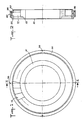
- a CMC turbine distributor for a turbo-reactor is produced in accordance with the invention by assembling a vane hub 10, two toothed rings 20, 30 and a ring 40 interposed between the two rings.
- the blade hub 10 is made in a single piece from CMC and comprises a plurality of blades 12 distributed regularly around a central part 13 forming a hub.
- the blades 12 define between them passages or channels 11 intended to channel the flow of gases between the combustion chamber and the turbine rotor of the turbo-reactor.
- a tenon or finger 14 projects radially from the outer end surface 12 a of each blade, in the central part of this surface.
- Each of the toothed rings 20.30 is made in one piece from CMC.
- the rings 20, 30 wear teeth, respec 21, 31, oriented in an axial direction and facing each other.
- the teeth of the rings 20, 30 are similar and are arranged according to the same diameter slightly greater than the outside diameter of the blade hub 10, pins not included. In this way, the rings 20 and 30 can be brought closer to each other, from the opposite sides of the blade hub, passing outside the end surfaces 15 of the blades 12 and leaving a radial clearance with these.
- the number and the arrangement of the teeth 21, 31 are chosen so that each tenon 14 of a blade is immobilized axially and circumferentially between a flank 22 of a tooth 21 and a flank 32 of a tooth 31 when the two rings 20, 30 are applied to each other.
- the teeth 21, 31 are distributed regularly along the rings 20, 30 and are in number equal to that of the blades 12; in addition, the thickness of the teeth 21, 31 and the height of the tenons 14 are chosen such that the tenons do not project radially beyond the external cylindrical surfaces 24, 34 of the teeth of the rings 20, 30.
- the ring 40 is made in one piece in CMC. It is arranged between the rings 20, 30, outside the teeth 21, 31, to radially close the gap between the rings 20, 30.
- the internal diameter of the ring 40 is such that it spares a radial clearance at least with the ends of the tenons 14 and, optionally, with the surfaces 24, 34.
- the ring 40 is housed between two external annular flanges 25, 35 of the rings 20, 30.
- the CMC constituting the parts 10, 20, 30, 40 is a material comprising a fibrous reinforcement in refractory fibers, for example carbon or ceramic fibers such as silicon carbide or alumina, and a ceramic matrix, for example also silicon carbide or alumina.
- Each of the parts 10, 20, 30, 40 can be obtained by first producing a cylindrical preform, for example by winding a fibrous texture, such as a fabric, constituting the fibrous reinforcement, then by densifying it by infiltration of the ceramic material constituting the matrix. Densification can be carried out by chemical vapor infiltration, possibly after deposition of an interphase material between the fibers of the reinforcement and the matrix. Methods of making CMC are well known, so a more detailed description is not necessary.
- each part is machined to its final shape, in particular to form the blades of the blade hub 10, and the teeth of the rings 20, 30.
- each stud 14 has two opposite faces 15, 16 which are carried against the sides 22, 32 of two teeth 21, 31 between which the stud is immobilized.
- the teeth of the rings 20, 30 are in mutual contact by the other sides 23, 33 of the teeth 21, 31.
- the sides 22, 32 between which the tenons 14 are immobilized are inclined at an angle a not zero with respect to the axial direction, so that each tenon is immobilized both axially and circumferentially. It is desirable that the pins 14 are carried on the sides 22, 32 over the largest possible area.
- the pins 14 can be produced with their largest face oriented substantially like the faces of the blades 12, as can be seen in FIG. 4 where a blade 12 is shown in dashes.
- the value of the angle a is therefore practically imposed by the arrangement of the blades 12. This value is between 0 and 30 °, for example around 15 °.
- each stud 14 causes it to tend to separate the teeth 21, 31 between which it is immobilized.
- the flanks 23, 33 of the teeth in mutual contact form ramps inclined at an angle b relative to the axial direction so that the expansion of the tenons results in a relative rotation with mutual spacing of the rings 20, 30, as shown in amplified by FIG. 5.
- the angle b of inclination of the sides 23, 33 is chosen to favor such a relative shift. It is preferably between 30 and 60 °, for example equal to 45 °.
- the mounting of the distributor in the casing of the turbo-reactor must be carried out so as to keep the distributor stationary with respect to the casing while allowing a relative movement of small amplitude both in rotation and in axial direction between the rings 20 and 30.
- the rings 20 and 30 applied towards each other are held in place by a flange 42 enclosing the rings 20, 30 with the interposition of a ring 41 which is elastically deformable at least in the direction axial while supporting a shear of limited amplitude.
- the ring 41 is advantageously constituted by a graphite seal in radially oriented sheets.
- the rings 20, 30 are thus permanently elastically biased towards one another in the axial direction.
- the mechanical connection of the distributor with the turbo-reactor casing is ensured by means of pins 44 integral with the casing, which penetrate into notches 36 formed at equal distance from each other at the peripheral of the ring 30 (FIGS. 1, 2 and 6).
- the notches 36 are for example four in number.
Landscapes
- Engineering & Computer Science (AREA)
- Mechanical Engineering (AREA)
- General Engineering & Computer Science (AREA)
- Chemical & Material Sciences (AREA)
- Ceramic Engineering (AREA)
- Turbine Rotor Nozzle Sealing (AREA)
- Physical Or Chemical Processes And Apparatus (AREA)
- Structures Of Non-Positive Displacement Pumps (AREA)
Applications Claiming Priority (2)
| Application Number | Priority Date | Filing Date | Title |
|---|---|---|---|
| FR8906748 | 1989-05-23 | ||
| FR8906748A FR2647502B1 (fr) | 1989-05-23 | 1989-05-23 | Distributeur de turbine pour turbo-reacteur et son procede de fabrication |
Publications (2)
| Publication Number | Publication Date |
|---|---|
| EP0399879A1 true EP0399879A1 (de) | 1990-11-28 |
| EP0399879B1 EP0399879B1 (de) | 1993-02-03 |
Family
ID=9381931
Family Applications (1)
| Application Number | Title | Priority Date | Filing Date |
|---|---|---|---|
| EP90401321A Expired - Lifetime EP0399879B1 (de) | 1989-05-23 | 1990-05-18 | Leitschaufelzusammenbau für Strahltriebwerk und Verfahren zu dessen Herstellung |
Country Status (6)
| Country | Link |
|---|---|
| US (1) | US5074749A (de) |
| EP (1) | EP0399879B1 (de) |
| CA (1) | CA2017263C (de) |
| DE (1) | DE69000854T2 (de) |
| ES (1) | ES2039116T3 (de) |
| FR (1) | FR2647502B1 (de) |
Cited By (1)
| Publication number | Priority date | Publication date | Assignee | Title |
|---|---|---|---|---|
| WO2010146288A1 (fr) | 2009-06-18 | 2010-12-23 | Snecma | Element de distributeur de turbine en cmc, procede de fabrication, et distributeur et turbine a gaz l'incorporant |
Families Citing this family (13)
| Publication number | Priority date | Publication date | Assignee | Title |
|---|---|---|---|---|
| US5704762A (en) * | 1993-11-08 | 1998-01-06 | Alliedsignal Inc. | Ceramic-to-metal stator vane assembly |
| US5411368A (en) * | 1993-11-08 | 1995-05-02 | Allied-Signal Inc. | Ceramic-to-metal stator vane assembly with braze |
| US5788456A (en) * | 1997-02-21 | 1998-08-04 | Dresser-Rand Company | Turbine diaphragm assembly and method thereof |
| US6000906A (en) * | 1997-09-12 | 1999-12-14 | Alliedsignal Inc. | Ceramic airfoil |
| JP3722188B2 (ja) | 1999-01-28 | 2005-11-30 | 石川島播磨重工業株式会社 | セラミックス基複合部材及びその製造方法 |
| US6200092B1 (en) * | 1999-09-24 | 2001-03-13 | General Electric Company | Ceramic turbine nozzle |
| JP5091615B2 (ja) * | 2007-10-15 | 2012-12-05 | 三菱重工業株式会社 | 静翼環セグメントの組立方法、静翼環セグメント、結合部材、溶接方法 |
| EP2431571B1 (de) * | 2010-09-16 | 2013-06-05 | Techspace Aero S.A. | Montageverbund durch Auflagerung aus Laufradschaufel und Träger |
| US8696311B2 (en) | 2011-03-29 | 2014-04-15 | Pratt & Whitney Canada Corp. | Apparatus and method for gas turbine engine vane retention |
| US8770931B2 (en) * | 2011-05-26 | 2014-07-08 | United Technologies Corporation | Hybrid Ceramic Matrix Composite vane structures for a gas turbine engine |
| EP2971578B1 (de) * | 2013-03-15 | 2020-05-06 | United Technologies Corporation | Verfahren zum zusammenbau einer gasturbinentriebwerksfrontstruktur und zugehörige gasturbinentriebwerksfrontstruktur |
| DE102013213834A1 (de) * | 2013-07-15 | 2015-02-19 | MTU Aero Engines AG | Verfahren zum Herstellen eines Isolationselements und Isolationselement für ein Gehäuse eines Flugtriebwerks |
| US10746035B2 (en) | 2017-08-30 | 2020-08-18 | General Electric Company | Flow path assemblies for gas turbine engines and assembly methods therefore |
Citations (9)
| Publication number | Priority date | Publication date | Assignee | Title |
|---|---|---|---|---|
| FR389268A (fr) * | 1907-04-20 | 1908-09-04 | Carl Roth | Système de fixation des aubes de turbines à vapeur et autres machines analogues |
| FR896203A (fr) * | 1942-07-09 | 1945-02-15 | Wagner Hochdruck Dampfturbinen | Supports d'aubes directrices pour turbines à vapeur ou à gaz |
| GB828248A (en) * | 1956-04-16 | 1960-02-17 | Gen Electric | Improvements in turbine and compressor blade cover assembly |
| US3042366A (en) * | 1958-05-05 | 1962-07-03 | Holmquist Ernst Rudolf Magnus | Axial flow gas turbine |
| US3357082A (en) * | 1963-02-13 | 1967-12-12 | Whiton Machine Company | Method of making a turbine wheel |
| GB1096257A (en) * | 1966-06-10 | 1967-12-20 | Rolls Royce | Gas turbine engine |
| US3677663A (en) * | 1970-10-01 | 1972-07-18 | Avco Corp | Damped turbomachine rotor assembly |
| EP0172082A1 (de) * | 1984-07-20 | 1986-02-19 | SOCIETE EUROPEENNE DE PROPULSION (S.E.P.) Société Anonyme dite: | Verfahren zur Herstellung eines Verbundkörpers mit feuerfester Faserverstärkung und keramischer Matrix, sowie damit hergestelltes Gefüge |
| US4643636A (en) * | 1985-07-22 | 1987-02-17 | Avco Corporation | Ceramic nozzle assembly for gas turbine engine |
Family Cites Families (7)
| Publication number | Priority date | Publication date | Assignee | Title |
|---|---|---|---|---|
| US2221684A (en) * | 1938-08-27 | 1940-11-12 | Gen Electric | Elastic fluid turbine bucket wheel |
| US3367630A (en) * | 1967-01-16 | 1968-02-06 | Westinghouse Electric Corp | Continuous shroud structure |
| US3905723A (en) * | 1972-10-27 | 1975-09-16 | Norton Co | Composite ceramic turbine rotor |
| US3900626A (en) * | 1973-09-04 | 1975-08-19 | United Aircraft Corp | Tantalum wire reinforced silicon nitride articles and method for making the same |
| US4066384A (en) * | 1975-07-18 | 1978-01-03 | Westinghouse Electric Corporation | Turbine rotor blade having integral tenon thereon and split shroud ring associated therewith |
| JPS5311201A (en) * | 1976-07-20 | 1978-02-01 | Mitsubishi Heavy Ind Ltd | Infinite cascade structure for rotary machines |
| DE2635830A1 (de) * | 1976-08-09 | 1978-02-16 | Siemens Ag | Anordnung zur befestigung eines deckbandes an turbinenschaufeln |
-
1989
- 1989-05-23 FR FR8906748A patent/FR2647502B1/fr not_active Expired - Fee Related
-
1990
- 1990-05-18 EP EP90401321A patent/EP0399879B1/de not_active Expired - Lifetime
- 1990-05-18 ES ES199090401321T patent/ES2039116T3/es not_active Expired - Lifetime
- 1990-05-18 DE DE9090401321T patent/DE69000854T2/de not_active Expired - Fee Related
- 1990-05-21 US US07/526,179 patent/US5074749A/en not_active Expired - Lifetime
- 1990-05-22 CA CA002017263A patent/CA2017263C/en not_active Expired - Fee Related
Patent Citations (9)
| Publication number | Priority date | Publication date | Assignee | Title |
|---|---|---|---|---|
| FR389268A (fr) * | 1907-04-20 | 1908-09-04 | Carl Roth | Système de fixation des aubes de turbines à vapeur et autres machines analogues |
| FR896203A (fr) * | 1942-07-09 | 1945-02-15 | Wagner Hochdruck Dampfturbinen | Supports d'aubes directrices pour turbines à vapeur ou à gaz |
| GB828248A (en) * | 1956-04-16 | 1960-02-17 | Gen Electric | Improvements in turbine and compressor blade cover assembly |
| US3042366A (en) * | 1958-05-05 | 1962-07-03 | Holmquist Ernst Rudolf Magnus | Axial flow gas turbine |
| US3357082A (en) * | 1963-02-13 | 1967-12-12 | Whiton Machine Company | Method of making a turbine wheel |
| GB1096257A (en) * | 1966-06-10 | 1967-12-20 | Rolls Royce | Gas turbine engine |
| US3677663A (en) * | 1970-10-01 | 1972-07-18 | Avco Corp | Damped turbomachine rotor assembly |
| EP0172082A1 (de) * | 1984-07-20 | 1986-02-19 | SOCIETE EUROPEENNE DE PROPULSION (S.E.P.) Société Anonyme dite: | Verfahren zur Herstellung eines Verbundkörpers mit feuerfester Faserverstärkung und keramischer Matrix, sowie damit hergestelltes Gefüge |
| US4643636A (en) * | 1985-07-22 | 1987-02-17 | Avco Corporation | Ceramic nozzle assembly for gas turbine engine |
Cited By (1)
| Publication number | Priority date | Publication date | Assignee | Title |
|---|---|---|---|---|
| WO2010146288A1 (fr) | 2009-06-18 | 2010-12-23 | Snecma | Element de distributeur de turbine en cmc, procede de fabrication, et distributeur et turbine a gaz l'incorporant |
Also Published As
| Publication number | Publication date |
|---|---|
| DE69000854T2 (de) | 1993-08-19 |
| CA2017263A1 (en) | 1990-11-23 |
| US5074749A (en) | 1991-12-24 |
| DE69000854D1 (de) | 1993-03-18 |
| CA2017263C (en) | 1999-12-28 |
| FR2647502B1 (fr) | 1991-09-13 |
| FR2647502A1 (fr) | 1990-11-30 |
| ES2039116T3 (es) | 1993-08-16 |
| EP0399879B1 (de) | 1993-02-03 |
Similar Documents
| Publication | Publication Date | Title |
|---|---|---|
| EP0399879B1 (de) | Leitschaufelzusammenbau für Strahltriebwerk und Verfahren zu dessen Herstellung | |
| CA2986661C (fr) | Ensemble d'anneau de turbine | |
| EP3433471B1 (de) | Turbinendeckbandanordnung mit spezifischer aufhängung im kalten zustand | |
| EP0243274B1 (de) | Unterteilter Dichtring für Turbinen | |
| EP3737837B1 (de) | Turbinenringanordnung | |
| EP0761978B1 (de) | Rotor aus thermostrukturellem Verbundmaterial, insbesondere mit grossem Diameter und sein Herstellungsverfahren | |
| EP3390783B1 (de) | Turbinendeckbandanordung und zugehörige turbine | |
| EP3390782B1 (de) | In einem kaltzustand elastisch gehaltene turbinenringanordnung | |
| EP3870807A1 (de) | Turbinenringanordnung mit gekrümmten geradlinigen aufnahmen | |
| EP1406019B1 (de) | Trommelrotor für eine Turbomaschine | |
| EP2811121B1 (de) | Verbundgehäuse für einen Kompressor einer axialen Turbomaschine mit Metallbefestigungsflansch | |
| FR2940353A1 (fr) | Roue mobile de turbomachine a aubes en materiau composite. | |
| FR2961847A1 (fr) | Roue mobile a aubes en materiau composite pour moteur a turbine a gaz a liaison pied d'aube/disque par serrage | |
| FR2963383A1 (fr) | Aube de turbomachine, rotor, turbine basse pression et turbomachine equipes d'une telle aube | |
| EP3274565B1 (de) | Turbinenringanordnung mit besonderer haltevorrichtung von ringsegmenten aus keramischen faserverbundwerkstoff | |
| EP0479632B1 (de) | Turbinenrad aus Verbundwerkstoff | |
| EP0466602B1 (de) | Statorschaufeln für Turbinen, hergestellt aus einem thermostrukturellen Verbundmaterial | |
| WO2017194860A1 (fr) | Ensemble d'anneau de turbine avec calage a froid | |
| FR2761418A1 (fr) | Appareil pour le transport d'un milieu | |
| EP1617046B1 (de) | Wellen- und Lageranordnung | |
| EP2483431B1 (de) | Förderrolle einer hochtemperatur-glühstrecke | |
| FR3146948A1 (fr) | Roue aubagee pour turbomachine d’aeronef, comprenant un dispositif d’amortissement dynamique realise a l’aide d’un organe de reconstitution d’une veine de circulation des gaz | |
| FR2559834A1 (fr) | Anneau de turbine | |
| FR3096726A1 (fr) | Ensemble pour turbine de turbomachine |
Legal Events
| Date | Code | Title | Description |
|---|---|---|---|
| PUAI | Public reference made under article 153(3) epc to a published international application that has entered the european phase |
Free format text: ORIGINAL CODE: 0009012 |
|
| AK | Designated contracting states |
Kind code of ref document: A1 Designated state(s): BE DE ES GB IT SE |
|
| 17P | Request for examination filed |
Effective date: 19901217 |
|
| 17Q | First examination report despatched |
Effective date: 19920416 |
|
| ITF | It: translation for a ep patent filed | ||
| GRAA | (expected) grant |
Free format text: ORIGINAL CODE: 0009210 |
|
| AK | Designated contracting states |
Kind code of ref document: B1 Designated state(s): BE DE ES GB IT SE |
|
| REF | Corresponds to: |
Ref document number: 69000854 Country of ref document: DE Date of ref document: 19930318 |
|
| GBT | Gb: translation of ep patent filed (gb section 77(6)(a)/1977) |
Effective date: 19930219 |
|
| REG | Reference to a national code |
Ref country code: ES Ref legal event code: FG2A Ref document number: 2039116 Country of ref document: ES Kind code of ref document: T3 |
|
| PLBE | No opposition filed within time limit |
Free format text: ORIGINAL CODE: 0009261 |
|
| STAA | Information on the status of an ep patent application or granted ep patent |
Free format text: STATUS: NO OPPOSITION FILED WITHIN TIME LIMIT |
|
| 26N | No opposition filed | ||
| EAL | Se: european patent in force in sweden |
Ref document number: 90401321.6 |
|
| REG | Reference to a national code |
Ref country code: ES Ref legal event code: PC2A |
|
| REG | Reference to a national code |
Ref country code: GB Ref legal event code: 732E |
|
| REG | Reference to a national code |
Ref country code: GB Ref legal event code: IF02 |
|
| PGFP | Annual fee paid to national office [announced via postgrant information from national office to epo] |
Ref country code: SE Payment date: 20030417 Year of fee payment: 14 |
|
| PGFP | Annual fee paid to national office [announced via postgrant information from national office to epo] |
Ref country code: DE Payment date: 20030512 Year of fee payment: 14 |
|
| PGFP | Annual fee paid to national office [announced via postgrant information from national office to epo] |
Ref country code: GB Payment date: 20030513 Year of fee payment: 14 |
|
| PGFP | Annual fee paid to national office [announced via postgrant information from national office to epo] |
Ref country code: ES Payment date: 20030514 Year of fee payment: 14 |
|
| PGFP | Annual fee paid to national office [announced via postgrant information from national office to epo] |
Ref country code: BE Payment date: 20030603 Year of fee payment: 14 |
|
| PG25 | Lapsed in a contracting state [announced via postgrant information from national office to epo] |
Ref country code: GB Free format text: LAPSE BECAUSE OF NON-PAYMENT OF DUE FEES Effective date: 20040518 |
|
| PG25 | Lapsed in a contracting state [announced via postgrant information from national office to epo] |
Ref country code: SE Free format text: LAPSE BECAUSE OF NON-PAYMENT OF DUE FEES Effective date: 20040519 Ref country code: ES Free format text: LAPSE BECAUSE OF NON-PAYMENT OF DUE FEES Effective date: 20040519 |
|
| PG25 | Lapsed in a contracting state [announced via postgrant information from national office to epo] |
Ref country code: BE Free format text: LAPSE BECAUSE OF NON-PAYMENT OF DUE FEES Effective date: 20040531 |
|
| BERE | Be: lapsed |
Owner name: SOCIETE NATIONALE D'ETUDE ET DE CONSTRUCTION DE MO Effective date: 20040531 |
|
| PG25 | Lapsed in a contracting state [announced via postgrant information from national office to epo] |
Ref country code: DE Free format text: LAPSE BECAUSE OF NON-PAYMENT OF DUE FEES Effective date: 20041201 |
|
| EUG | Se: european patent has lapsed | ||
| GBPC | Gb: european patent ceased through non-payment of renewal fee |
Effective date: 20040518 |
|
| PG25 | Lapsed in a contracting state [announced via postgrant information from national office to epo] |
Ref country code: IT Free format text: LAPSE BECAUSE OF NON-PAYMENT OF DUE FEES;WARNING: LAPSES OF ITALIAN PATENTS WITH EFFECTIVE DATE BEFORE 2007 MAY HAVE OCCURRED AT ANY TIME BEFORE 2007. THE CORRECT EFFECTIVE DATE MAY BE DIFFERENT FROM THE ONE RECORDED. Effective date: 20050518 |
|
| REG | Reference to a national code |
Ref country code: ES Ref legal event code: FD2A Effective date: 20040519 |