EP0400014B1 - Rohrbündelreaktor - Google Patents
Rohrbündelreaktor Download PDFInfo
- Publication number
- EP0400014B1 EP0400014B1 EP89900237A EP89900237A EP0400014B1 EP 0400014 B1 EP0400014 B1 EP 0400014B1 EP 89900237 A EP89900237 A EP 89900237A EP 89900237 A EP89900237 A EP 89900237A EP 0400014 B1 EP0400014 B1 EP 0400014B1
- Authority
- EP
- European Patent Office
- Prior art keywords
- tube
- tubes
- heat
- transfer medium
- reaction
- Prior art date
- Legal status (The legal status is an assumption and is not a legal conclusion. Google has not performed a legal analysis and makes no representation as to the accuracy of the status listed.)
- Expired - Lifetime
Links
Images
Classifications
-
- B—PERFORMING OPERATIONS; TRANSPORTING
- B01—PHYSICAL OR CHEMICAL PROCESSES OR APPARATUS IN GENERAL
- B01J—CHEMICAL OR PHYSICAL PROCESSES, e.g. CATALYSIS OR COLLOID CHEMISTRY; THEIR RELEVANT APPARATUS
- B01J8/00—Chemical or physical processes in general, conducted in the presence of fluids and solid particles; Apparatus for such processes
- B01J8/02—Chemical or physical processes in general, conducted in the presence of fluids and solid particles; Apparatus for such processes with stationary particles, e.g. in fixed beds
- B01J8/06—Chemical or physical processes in general, conducted in the presence of fluids and solid particles; Apparatus for such processes with stationary particles, e.g. in fixed beds in tube reactors; the solid particles being arranged in tubes
- B01J8/067—Heating or cooling the reactor
-
- B—PERFORMING OPERATIONS; TRANSPORTING
- B01—PHYSICAL OR CHEMICAL PROCESSES OR APPARATUS IN GENERAL
- B01J—CHEMICAL OR PHYSICAL PROCESSES, e.g. CATALYSIS OR COLLOID CHEMISTRY; THEIR RELEVANT APPARATUS
- B01J2208/00—Processes carried out in the presence of solid particles; Reactors therefor
- B01J2208/00008—Controlling the process
- B01J2208/00017—Controlling the temperature
- B01J2208/00106—Controlling the temperature by indirect heat exchange
- B01J2208/00168—Controlling the temperature by indirect heat exchange with heat exchange elements outside the bed of solid particles
- B01J2208/00212—Plates; Jackets; Cylinders
- B01J2208/00221—Plates; Jackets; Cylinders comprising baffles for guiding the flow of the heat exchange medium
-
- B—PERFORMING OPERATIONS; TRANSPORTING
- B01—PHYSICAL OR CHEMICAL PROCESSES OR APPARATUS IN GENERAL
- B01J—CHEMICAL OR PHYSICAL PROCESSES, e.g. CATALYSIS OR COLLOID CHEMISTRY; THEIR RELEVANT APPARATUS
- B01J2219/00—Chemical, physical or physico-chemical processes in general; Their relevant apparatus
- B01J2219/00761—Details of the reactor
- B01J2219/00763—Baffles
- B01J2219/00765—Baffles attached to the reactor wall
- B01J2219/00777—Baffles attached to the reactor wall horizontal
Definitions
- the invention relates to a tube bundle reactor according to the preamble of claim 1.
- Such tube bundle reactors represent a frequently desired and often indispensable construction and operating form of larger chemical reactors. They can be designed with parallel, radial, cross-flow or double cross-flow guidance of the heat transfer medium, which means that the main flow direction forced by internals such as deflection and / or distributor plates Heat carrier is referred to in relation to the reaction tube bundle.
- Heat carrier is referred to in relation to the reaction tube bundle.
- the heat transfer medium entering the reactor housing is forced to initially make its way along the tube plate or partition plate there.
- the problem arises that a portion of the heat transfer fluid which runs more or less directly along the relevant tube sheet or separating plate cools to an undesirably high degree.
- reaction gas entering there may be, for example, a temperature of 100 or 150 ° C.
- reaction temperature and consequently the temperature of the heat transfer medium is, for example, 400 ° C.
- the temperature differences caused by the disproportionate cooling mentioned above between different layers of the heat carrier remain to a greater or lesser extent also in the further course of the flow and consequently lead to different temperatures as well as temperature profiles of the individual contact tubes, which can affect yield and selectivity.
- To reduce the temperature differences mentioned by increasing the flow rate of the heat transfer medium would cause a disproportionate increase in the pump output and thus also in the energy consumption.
- the invention is therefore based on the object of designing a tube bundle reactor according to the generic term in such a way that temperatures and temperature profiles of the individual contact tubes can be kept largely the same without the need for a significant increase in the pump output.
- the bypass channel in question has the effect that the proportion of the heat transfer medium which has been disproportionately cooled on the inlet-side tube plate or separating plate, bypassing the contact tube bundle, including any other flow-conducting internals, such as deflection and distributor plates, is located directly to the outlet area of the heat transfer medium or in any case a location closer to it within the reactor housing where its comparatively low temperature is harmless or even desirable.
- the latter can be the case, for example, at the height of the hot spot and there again in the interior of an inward deflecting plate.
- the bypass duct according to the invention is structurally simple to implement. Although it requires a free space in the middle of the tube bundle, it is anyway expedient in the case of larger reactors for fluidic reasons, as set out in DE-PS 25 59 661.
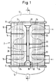
- the tube bundle reactor 2 shown in Fig. 1 contains a cylindrical reaction tube bundle 4, which in tube plates 6 and 8 ends.
- the reaction gas is fed to the tube bundle 4 from below through a hood 10, while a top hood 12 of the same type collects the converted gas which has passed through the tube bundle.
- the interior of the reactor 2 between the tube sheets 6 and 8 is filled outside of the tubes of the tube bundle 4 by a heat transfer medium, for example a molten salt, which feeds the reactor housing 14 in the vicinity of the lower tube sheet 6 radially through an annular channel 16 and accordingly in the vicinity of the upper tube sheet 8 through an annular channel 18 and an external heat exchanger, not shown, is supplied.
- a heat transfer medium for example a molten salt
- the heat transfer medium is forced to flow in a meandering manner around deflection plates 20 and 22 arranged in different planes, in order to pass the tube bundle essentially "in cross flow", ie radially here.
- the baffles 20 and 22 usually have openings for the individual tubes, which leave a gap around them, and the individual gaps can be dimensioned such that a more or less large partial flow of the heat transfer medium can pass through there in the axial direction of the reactor in order to to provide a desired temperature field in the tube bundle 4 (see, for example, DE-OS 2 201 528 / positions 7 and 8).
- the reactor 2 is of the type which, in the interior of the tube bundle 4, has a coaxial cylindrical interior which is kept free from contact tubes (cf. DE-OS 25 59 661).
- the reaction gas enters through the hood 10 into the tube bundle at a temperature of about 100 ° C, for example.
- the lower tube sheet 6 is naturally cooled to a considerable extent, and this cooling effect is also communicated to the layers of the heat carrier adjoining it. Since these layers do not remain at rest, but form a partial flow, as indicated by the arrows 24, it usually occurs that this subcooled partial flow cools the tube bundle to temperatures which are not yet satisfactorily controllable to temperatures which are detrimental to the course of the reaction.
- a bypass channel 26 is now provided in the reactor 2 shown for the partial flow indicated by the arrows 24, which in this case consists of a coaxial guide tube 28 with funnel-like extensions 30 and 32 at both ends near the tube plate 6 or 8.
- the partial flow of the heat carrier indicated by the arrows 24 is fed directly to the outlet end of the tube bundle 4 without being able to make further contact with the tube bundle up to that point.
- this partial flow finds its way outward to the ring channel 18, approximately in the same way as it found from the ring channel 16 into the center of the tube bundle. It can be assumed that the reaction at the outlet end of the tube bundle 4 is complete, and there it is anyway desirable to intensify the cooling of the converted gas.
- the cylindrical peripheral inlet cross section between the tube sheet 6 and the extension 32 can be covered with a sieve-like perforated plate 36, as shown.
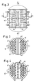
- a tube bundle reactor 40 is shown, which instead of a hollow cylindrical tube bundle according to FIG. 1 has two tube bundle groups 42 and 44 which are at a distance from one another and is accordingly flowed through by the heat carrier entering on opposite sides in a so-called double cross-flow, while its other internal one Structure with alternating deflection plates 46 and 48 corresponds in principle to that of FIG. 1.
- FIG. 3 and 4 show two different embodiments of the same.
- the bypass channel 50 essentially consists of a box-shaped guide channel 52 that extends over the entire width of the reactor 40, and according to FIG. 4 it consists of a row of individual guide tubes 54.
- extensions similar to extensions 30 and 32 can be made at both ends 1, and a perforated plate similar to the perforated plate 36 can also be located on the inlet cross section for improved flow guidance.
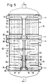
- the reactor housing 72 with a continuous tube bundle, is divided by a separating plate 74 into two superposed heat exchange sections 76 and 78, which are at least substantially separated from one another, as is likewise the case from DE-OS 2 201 528 is known.
- a separating plate 74 instead of alternating baffles 20 and 22 between the respective ring channels 68 and 70 in the immediate vicinity of the same, continuous distributor plates 80 with annular gaps around the individual reaction tubes are provided in the heat exchange section 78, which cause an essentially axially directed flow of the heat transfer medium along these .
- a bypass channel 82 is again provided in the form of a central guide tube 84 which is enlarged at both ends, as in the reactor 2 according to FIG. 1.
- the heat exchange section 76 underneath has a central guide tube 86, but in this example this is still coaxially surrounded by a further guide tube 88 in order to form two separate bypass channels, 90 and 92.
- the partial flow of the heat transfer medium indicated by the arrows 94 and 96 can be discharged in layers from the region of the lower tube sheet 98, it being assumed that the portion passing through the gap between the guide tubes 86 and 88 has a smaller temperature difference with respect to the entering heat transfer medium than the one passing through the guide tube 86. In the present case, this is used to supply the less supercooled portion to the tube bundle 62 at a point where an elevated temperature would be expected from the house.
- Such a point is usually the area of the hot spot and there again such a place within a radially inward deflecting plate, such as 100. Accordingly, the guide tube 88 is allowed to end in this area, again with an extension 102, so that the partial flow of the heat transfer medium emerging there can mix with the main flow, which is indicated in its main course by the arrowed lines 104.
Landscapes
- Chemical & Material Sciences (AREA)
- Organic Chemistry (AREA)
- Chemical Kinetics & Catalysis (AREA)
- Devices And Processes Conducted In The Presence Of Fluids And Solid Particles (AREA)
- Physical Or Chemical Processes And Apparatus (AREA)
Abstract
Description
- Die Erfindung betrifft einen Rohrbündelreaktor gemäß Gattungsbegriff des Anspruchs 1.
- Derartige Rohrbündelreaktoren stellen eine häufig gewünschte und vielfach unverzichtbare Bau- und Betriebsform größerer Chemiereaktoren dar. Sie können mit Parallel-, Radial-, Querstrom- oder doppelter Querstromführung des Wärmeträgers ausgeführt sein, womit die durch Einbauten wie Umlenk- und/oder Verteilerbleche erzwungene Hauptströmungsrichtung des Wärmeträgers in bezug auf das Reaktionsrohrbündel bezeichnet ist. In jedem Fall ist der in das Reaktorgehäuse eintretende Wärmeträger gezwungen, zu einem wesentlichen Teil seinen Weg zunächst einmal entlang dem dortigen Rohrboden oder Trennblech zu nehmen. Dabei erhebt sich mit zunehmender Länge der betreffenden Querströmung und zunehmendem dortigem Temperaturunterschied zwischen Reaktionsgas und Wärmeträger in zunehmendem Maße das Problem, daß sich ein an dem betreffenden Rohrboden bzw. Trennblech mehr oder weniger unmittelbar entlangstreichender Anteil des Wärmeträgers in unerwünscht starkem Maße abkühlt. Dies ist verständlich, hält man sich vor Augen, daß das dort eintretende Reaktionsgas beispielsweise eine Temperatur von 100 oder 150 °C haben mag, während die Reaktionstemperatur und infolgedessen auch die Temperatur des Wärtmeträgers bei beispielsweise 400 °C liegt. Die durch die erwähnte unverhältnismäßig starke Abkühlung bewirkten Temperaturunterschiede zwischen verschiedenen Schichten des Wärmeträgers bleiben in mehr oder weniger starkem Maße auch im weiteren Strömungsverlauf bestehen und führen infolgedessen zu unterschiedlichen Temperaturen wie auch Temperaturprofilen der einzelnen Kontaktrohre, worunter Ausbeute und Selektivität leiden können. Die genannten Temperaturunterschiede durch Erhöhung der Durchflußgeschwindigkeit des Wärmeträgers zu verringern würde einen unverhältnismäßig starken Anstieg der Pumpenleistung und damit auch des Energieverbrauchs bedingen.
- Von daher liegt der Erfindung die Aufgabe zugrunde, einen Rohrbündelreaktor nach Gattungsbegriff so auszubilden, daß Temperaturen und Temperaturprofile der einzelnen Kontaktrohre weitgehend gleich gehalten werden können, ohne daß es dazu einer ins Gewicht fallenden Erhöhung der Pumpenleistung bedarf.
- Diese Aufgabe ist erfindungsgemäß durch das kennzeichnende Merkmal des Anspruchs 1 gelöst. Die Unteransprüche geben darüber hinausgehend vorteilhafte Ausgestaltungsmöglichkeiten an.
- Der betreffende Bypasskanal bewirkt, daß der an dem eintrittsseitigen Rohrboden oder Trennblech unverhältnismäßig stark abgekühlte Anteil des Wärmeträgers unter Umgehung des Kontaktrohrbündels samt eventuellen weiteren strömungsleitenden Einbauten, wie Umlenk- und Verteilerblechen, unmittelbar zum Austrittsbereich des Wärmeträgers oder jedenfalls einer diesem nähergelegenen Stelle innerhalb des Reaktorgehäuses findet, wo seine vergleichsweise geringe Temperatur unschädlich oder sogar erwünscht ist. Letzteres kann beispielsweise in der Höhe des Hot Spot und dort wiederum im Inneren eines nach innen reichenden Umlenkbleches der Fall sein.
- Der erfindungsgemäße Bypasskanal ist konstruktiv einfach zu verwirklichen. Er erfordert zwar in der Mitte des Rohrbündels einen Freiraum, jedoch ist ein solcher bei größeren Reaktoren aus strömungstechnischen Gründen ohnedies zweckmäßig, wie in der DE-PS 25 59 661 dargelegt.
- Nachfolgend werden einige Ausführungsbeispiele erfindungsgemäßer Rohrbündelreaktoren anhand der Zeichnungen genauer beschrieben. Dabei zeigt
- Fig. 1 einen stehenden Rohrbündelreaktor mit zylindrischem Rohrbündel, schematisiert im Mittellängsschnitt, wobei Reaktionsgas und Wärmeträger am unteren Ende eintreten,
- Fig. 2 in ähnlicher Darstellung einen Rohrbündelreaktor mit zwei einander gegenüberstehenden Rohrbündelgruppen und doppelter Querstromführung des Wärmeträgers,
- Fig. 3 und 4 jeweils, in einem schematischen Querschnitt des Reaktors nach Fig. 2 etwa in Höhe der Linie A-A, verschieden Ausführungen des betreffenden Bypasskanals und
- Fig. 5 in wiederum ähnlicher Darstellung wie Fig. 1 einen Rohrbündelreaktor mit zylindrischem Rohrbündel, wobei der den Wärmeträger aufnehmende Raum des Reaktorbehälters freilich durch ein Trennblech in zwei übereinanderliegende getrennte Abschnitte entsprechend stark unterschiedlichen Wärmeaustauschbedürfnissen unterteilt ist.
- Der in Fig. 1 dargestellte Rohrbündelreaktor 2 enthält ein zylindrisches Reaktionsrohrbündel 4, das in Rohrböden 6 und 8 endet. Dem Rohrbündel 4 wird das Reaktionsgas von unten her durch eine Haube 10 zugeführt, während eine ebensolche obere Haube 12 das durch das Rohrbündel hindurchgetretene, umgesetzte Gas sammelt. Der Innenraum des Reaktors 2 zwischen den Rohrböden 6 und 8 ist außerhalb der Rohre des Rohrbündels 4 von einem diese umspülenden Wärmeträger, beispielsweise einer Salzschmelze, erfüllt, der dem Reaktorgehäuse 14 in der Nähe des unteren Rohrbodens 6 radial durch einen Ringkanal 16 zugeführt und entsprechend in der Nähe des oberen Rohrbodens 8 durch einen Ringkanal 18 ab- und einem nicht gezeigten außenliegenden Wärmetauscher zugeführt wird. Zwischen den beiden Rohrböden 6 und 8 ist der Wärmeträger gezwungen, mäanderförmig um in verschiedenen Ebenen angeordnete Umlenkbleche 20 und 22 herumzuströmen, um das Rohrbündel so im wesentlichen "im Querstrom", d.h. hier radial, zu passieren. Die Umlenkbleche 20 und 22 weisen gewöhnlich Durchtrittsöffnungen für die einzelnen Rohre auf, die um diese herum einen Spalt bestehen lassen, und die einzelnen Spalte können so bemessen sein, daß ein mehr oder weniger großer Teilstrom des Wärmeträgers dort in Axialrichtung des Reaktors hindurchzutreten vermag, um in dem Rohrbündel 4 ein gewünschtes Temperaturfeld zu ergeben (vergl. insoweit beispielsweise die DE-OS 2 201 528 / Positionen 7 und 8). Der Reaktor 2 ist von demjenigen Typ, der im Inneren des Rohrbündels 4 einen koaxialen, von Kontaktrohren freigehaltenen zylindrischen Innenraum bestehen läßt (vergl. DE-OS 25 59 661).
- Während die mittlere Reaktionstemperatur in dem Rohrbündel 4 und damit auch die Temperatur des Wärmeträgers beispielsweise bei ca. 400 °C liegt, gleichgültig ob die Reaktion exotherm oder endotherm abläuft, tritt das Reaktionsgas durch die Haube 10 hindurch in das Rohrbündel mit einer Temperatur von beispielsweise ca. 100 °C ein. Hierdurch wird der untere Rohrboden 6 naturgemäß in erheblichem Maße gekühlt, und dieser Kühleffekt teilt sich auch den daran angrenzenden Schichten des Wärmeträgers mit. Da diese Schichten nicht in Ruhe bleiben, sondern einen Teilstrom bilden, wie er durch die Pfeile 24 angedeutet ist, kommt es normalerweise dazu, daß dieser unterkühlte Teilstrom das Rohrbündel an zudem noch nicht befriedigend kontrollierbaren Stellen auf Temperaturen kühlt, die dem Reaktionsverlauf abträglich sind.
- Um dem zu begegnen, ist nun in dem dargestellten Reaktor 2 für den durch die Pfeile 24 angegebenen Teilstrom ein Bypasskanal 26 vorgesehen, der in diesem Fall aus einem koaxialen Leitrohr 28 mit trichterartigen Erweiterungen 30 und 32 an seinen beiden Enden in der Nähe des Rohrbodens 6 bzw. 8 besteht. Durch diesen Bypasskanal 26 wird der durch die Pfeile 24 bezeichnete Teilstrom des Wärmeträgers unmittelbar dem Austrittsende des Rohrbündels 4 zugeführt, ohne mit dem Rohrbündel bis dahin weiter in Kontakt treten zu können. Am Austrittsende des Rohrbündels 4 in der Nähe des Rohrbodens 8 findet dieser Teilstrom gemäß Pfeilen 34 nach außen, zu dem Ringkanal 18, etwa in der gleichen Weise, wie er von dem Ringkanal 16 ins Zentrum des Rohrbündels gefunden hat. Dabei kann angenommen werden, daß die Reaktion am Austrittsende des Rohrbündels 4 abgeschlossen und dort eine verstärkte Kühlung des umgesetzten Gases ohnedies wünschenswert ist.
- Um die Strömung des genannten Teilstromes in und durch das Leitrohr 28 noch zu verbessern, kann der zylindrische periphere Eintrittsquerschnitt zwischen Rohrboden 6 und Erweiterung 32, wie gezeigt, mit einer siebartigen Lochplatte 36 abgedeckt sein.
- In Fig. 2 ist ein Rohrbündelreaktor 40 dargestellt, der anstelle eines hohlzylindrischen Rohrbündels gemäß Fig. 1 zwei mit Abstand einander gegenüberstehende Rohrbündelgruppen 42 und 44 aufweist und entsprechend von dem auf gegenüberliegenden Seiten eintretenden Wärmeträger im sog. doppelten Querstrom durchströmt wird, während sein sonstiger innerer Aufbau mit miteinander abwechselnden Umlenkblechen 46 und 48 prinzipiell demjenigen von Fig. 1 entspricht.
- In diesem Fall nun ist ein Bypasskanal 50 im Raum zwischen den beiden Rohrbündelgruppen 42 und 44 angeordnet. Die Figuren 3 und 4 zeigen zwei unterschiedliche Ausführungsformen desselben.
- Nach Fig. 3 besteht der Bypasskanal 50 im wesentlichen aus einem über die gesamte Breite des Reaktors 40 reichenden kastenförmigen Leitkanal 52, nach Fig. 4 aus einer Zeile einzelner Leitrohre 54. In jedem Fall können wiederum an beiden Enden Erweiterungen ähnlich den Erweiterungen 30 und 32 aus Fig. 1 vorgesehen sein, und ebenso kann sich am Eintrittsquerschnitt zur verbesserten Strömungsführung eine Lochplatte ähnlich der Lochplatte 36 befinden.
- Der Reaktor 60 nach Fig. 5 ähnelt mit einem hohlzylindrischen Rohrbündel 62 und Ringkanälen 64 bis 70 wiederum demjenigen aus Fig. 1. Indessen ist in diesem Fall das Reaktorgehäuse, 72, bei durchgehendem Rohrbündel durch ein Trennblech 74 in zwei übereinanderliegende, voneinander zumindest im wesentlichen getrennte Wärmetauschabschnitte 76 und 78 unterteilt, wie dies etwa gleichfalls aus der DE-OS 2 201 528 bekannt ist. Ebenso sind hier beispielsweise in dem Wärmetauschabschnitt 78 anstelle miteinander abwechselnder Umlenkbleche 20 und 22 zwischen den betreffenden Ringkanälen 68 und 70 in unmittelbarer Nähe derselben durchgehende Verteilerbleche 80 mit Ringspalten um die einzelnen Reaktionsrohre vorgesehen, durch welche diesen entlang eine im wesentlichen axialgerichtete Strömung des Wärmeträger hervorgerufen wird. Dies ändert jedoch nichts daran, daß ein unmittelbar an dem Trennblech 74 entlangstreichender Teilstrom des durch den betreffenden Ringkanal 68 eintretenden Wärmeträgers von dem Trennblech her eine unerwünscht starke Temperaturänderung erfahren kann. Aus diesem Grunde ist auch hier wieder ein Bypasskanal, 82, in Gestalt eines zentralen, an beiden Enden erweiterten Leitrohres 84 vorgesehen, wie bei dem Reaktor 2 nach Fig. 1.
- In gleicher Weise weist der darunterliegende Wärmetauschabschnitt 76 ein zentrales Leitrohr 86 auf, jedoch ist dieses in diesem Beispiel noch mit Abstand koaxial von einem weiteren Leitrohr, 88, umgeben, um zwei getrennte Bypasskanäle, 90 und 92, zu bilden. Auf diese Weise kann der durch die Pfeile 94 und 96 bezeichnete Teilstrom des Wärmeträgers aus dem Bereich des unteren Rohrbodens 98 geschichtet abgeführt werden, wobei davon auszugehen ist, daß der durch den Spalt zwischen den Leitrohren 86 und 88 hindurchtretende Anteil eine geringere Temperaturdifferenz gegenüber dem eintretenden Wärmeträger aufweist als der durch das Leitrohr 86 hindurchtretende. Dies macht man sich im vorliegenden Fall dafür zunutze, den geringer unterkühlten Anteil dem Rohrbündel 62 an einer Stelle zuzuführen, wo von Haus aus eine erhöhte Temperatur zu erwarten wäre. Eine solche Stelle ist in der Regel der Bereich des Hot Spot und dort wiederum ein solcher innerhalb eines radial nach innen weisenden Umlenkbleches wie z.B. 100. Demgemäß läßt man das Leitrohr 88 in diesem Bereich, wiederum mit einer Erweiterung, 102, enden, so daß sich der dort austretende Teilstrom des Wärmeträgers mit dem Hauptstrom mischen kann, der in seinem hauptsächlichen Verlauf durch die gepfeilten Linien 104 angegeben ist.
- Selbstredend sind nach den vorangehenden Angaben mancherlei weitere Spielarten und Kombinationsmöglichkeiten denkbar.
Claims (7)
- Rohrbündelreaktor für katalytische chemische Gasphasenreaktionen mit positiver oder negativer Wärmetönung, bei dem ein das Reaktionsrohrbündel umspülender Wärmeträger dem Reaktorgehäuse im wesentlichen normal zur Rohrachse von außen nach innen gerichtet in der Nähe eines gaseintrittsseitigen Rohrbodens oder Trennblechs mit von der dortigen Gastemperatur stark unterschiedlicher Temperatur zugeführt und von dem Reaktorgehäuse an einer in bezug auf das Reaktionsgas stromabwärts gelegenen Stelle ab- und einem außenliegenden Wärmetauscher zugeführt wird, dadurch gekennzeichnet , daß ein dem betreffenden Rohrboden (6; 98) bzw. Trennblech (74) unmittelbar benachbarter Teilstrom des zugeführten Wärmeträgers von dort weg durch einen im Zentrum des Rohrbündels (4; 42, 44; 62) angeordneten Bypasskanal (26; 50; 82; 90, 92) unter Umgehung der Reaktionsrohre einer stromabwärts, zum Austrittsbereich des Wärmeträgers hin gelegenen Stelle zugeführt wird.
- Rohrbündelreaktor nach Anspruch 1 mit zylindrischem Reaktionsrohrbündel und radialem Wärmeträgerein- und -austritt, wobei das Zentrum des Reaktionsrohrbündels von Röhren freigehalten ist, dadurch gekennzeichnet , daß der Bypasskanal (26; 82; 90, 92) im wesentlichen aus einem koaxial im Zentrum des Rohrbündels (4; 62) angeordneten Leitrohr (28; 84; 86, 88) besteht.
- Rohrbündelreaktor nach Anspruch 1 mit zwei einander mit Abstand gegenüberliegenden Reaktionsrohrbündelgruppen, dadurch gekennzeichnet , daß der Bypasskanal (50) in Gestalt eines einzigen kastenförmigen Leitkanals (52) oder einer Zeile nebeneinanderliegender Leitrohre (54) zwischen den beiden gegenüberliegenden Reaktionsrohrbündelgruppen (42, 44) angeordnet ist.
- Rohrbündelreaktor nach Anspruch 2 oder 3, dadurch gekennzeichnet , daß das jeweilige Leitrohr (28; 54; 84; 86, 88) bzw. der Leitkanal (52) ein- oder - vorzugsweise - beidendig eine trichterartige Erweiterung (30, 32; 102) aufweist.
- Rohrbündelreaktor nach einem der Ansprüche 2 bis 4, dadurch gekennzeichnet , daß der verfügbare periphere Eintrittsquerschnitt des jeweiligen Leitrohres (28; 54; 84; 86, 88) bzw. des Leitkanals (52) mit einer siebartigen Lochplatte (36) abgedeckt ist.
- Rohrbündelreaktor nach einem der vorhergehenden Ansprüche, dadurch gekennzeichnet , daß mehrere derartige Bypasskanäle (90, 92) ineinanderliegend angeordnet sind.
- Rohrbündelreaktor nach Anspruch 6, dadurch gekennzeichnet , daß der äußere (92) bzw. die äußeren der betreffenden ineinanderliegend angeordneten Bypasskanäle (90, 92) noch vor dem Austrittsbereich des Wärmeträgers - vorzugsweise im Bereich eines nach innen weisenden Umlenkblechs (100) - endet bzw. enden.
Applications Claiming Priority (1)
| Application Number | Priority Date | Filing Date | Title |
|---|---|---|---|
| PCT/EP1988/001146 WO1990006807A1 (de) | 1988-12-13 | 1988-12-13 | Rohrbündelreaktor |
Publications (2)
| Publication Number | Publication Date |
|---|---|
| EP0400014A1 EP0400014A1 (de) | 1990-12-05 |
| EP0400014B1 true EP0400014B1 (de) | 1992-09-16 |
Family
ID=8165353
Family Applications (1)
| Application Number | Title | Priority Date | Filing Date |
|---|---|---|---|
| EP89900237A Expired - Lifetime EP0400014B1 (de) | 1988-12-13 | 1988-12-13 | Rohrbündelreaktor |
Country Status (5)
| Country | Link |
|---|---|
| US (1) | US5161605A (de) |
| EP (1) | EP0400014B1 (de) |
| JP (1) | JPH03502422A (de) |
| DE (1) | DE3874759D1 (de) |
| WO (1) | WO1990006807A1 (de) |
Families Citing this family (27)
| Publication number | Priority date | Publication date | Assignee | Title |
|---|---|---|---|---|
| FR2655876B1 (fr) * | 1989-12-19 | 1994-03-11 | Pecquet Tesson Ste Indle | Reacteur pour reactions chimiques a catalyseurs. |
| DE4431957A1 (de) * | 1994-09-08 | 1995-03-16 | Basf Ag | Verfahren zur katalytischen Gasphasenoxidation von Propen zu Acrolein |
| DE4439807A1 (de) * | 1994-11-08 | 1996-05-09 | Basf Ag | Reaktor zur Durchführung heterogenkatalysierter Gasphasenreaktionen |
| GB9600350D0 (en) * | 1996-01-09 | 1996-03-13 | Ici Plc | Heat exchange catalytic reactor |
| US5820641A (en) * | 1996-02-09 | 1998-10-13 | Mks Instruments, Inc. | Fluid cooled trap |
| DE19836792A1 (de) * | 1998-08-13 | 2000-02-17 | Basf Ag | Reaktor mit einem Kontaktrohrbündel |
| US6384274B1 (en) | 1998-09-27 | 2002-05-07 | Rohm And Haas Company | Single reactor process for preparing acrylic acid from propylene having improved capacity |
| US6167951B1 (en) * | 1999-01-26 | 2001-01-02 | Harold Thompson Couch | Heat exchanger and method of purifying and detoxifying water |
| US6238514B1 (en) | 1999-02-18 | 2001-05-29 | Mks Instruments, Inc. | Apparatus and method for removing condensable aluminum vapor from aluminum etch effluent |
| US6197119B1 (en) | 1999-02-18 | 2001-03-06 | Mks Instruments, Inc. | Method and apparatus for controlling polymerized teos build-up in vacuum pump lines |
| DE60000708T2 (de) | 1999-06-28 | 2003-07-24 | Rohm And Haas Co., Philadelphia | Verfahren zur Herstellung von (Meth)acrylsäure |
| US6488745B2 (en) | 2001-03-23 | 2002-12-03 | Mks Instruments, Inc. | Trap apparatus and method for condensable by-products of deposition reactions |
| US7316804B2 (en) * | 2001-08-02 | 2008-01-08 | Ineos Usa Llc | Flow reactors for chemical conversions with heterogeneous catalysts |
| DE10144857A1 (de) * | 2001-09-12 | 2003-03-27 | Deggendorfer Werft Eisenbau | Reaktoranordnung für die Durchführung katalytischer Gasphasenreaktionen, insbesondere zur Gewinnung von Phthalsäureanhydrid |
| EP1569745B1 (de) * | 2002-12-12 | 2019-03-20 | MAN Energy Solutions SE | Mantelrohrreaktor für katalytische gasphasenreaktionen |
| JP4507711B2 (ja) * | 2004-06-15 | 2010-07-21 | 三菱化学株式会社 | 触媒反応器 |
| US7947232B2 (en) * | 2006-12-07 | 2011-05-24 | Exxonmobil Research & Engineering Company | HF alkylation reactor |
| PT2379216T (pt) * | 2008-12-16 | 2018-01-10 | Basf Se | Reator e processo para a produção de fosgénio |
| US20110259574A1 (en) * | 2010-04-23 | 2011-10-27 | Alstom Technology Ltd | Adjustable heat exchanger |
| US20110289940A1 (en) * | 2010-05-27 | 2011-12-01 | Lummus Technology Inc. | Liquid natural gas vaporization |
| CA2781246A1 (en) | 2011-07-14 | 2013-01-14 | Rohm And Haas Company | Method for removal of organic compounds from waste water streams in a process for production of (meth)acrylic acid |
| US9829214B2 (en) * | 2015-04-22 | 2017-11-28 | Ronald Paul Taylor | Cylindrical tubular heat exchanger type 1 |
| US9835357B2 (en) * | 2015-04-22 | 2017-12-05 | Ronald Paul Taylor | Cylindrical tubular heat exchanger type 2 |
| ITUB20150576A1 (it) * | 2015-04-24 | 2016-10-24 | Hexsol Italy Srl | Scambiatore di calore a fascio tubiero e struttura perfezionata |
| JP6956491B2 (ja) * | 2017-02-01 | 2021-11-02 | 株式会社Ihiプラント | 熱交換器及び熱交換システム |
| ES2881297T3 (es) * | 2017-02-10 | 2021-11-29 | Technobell D O O Koper | Reactor tubular de doble zona mejorado y método para llevar a cabo la producción de anhídrido maleico mediante la oxidación de n-butano |
| IT202200015270A1 (it) * | 2022-07-20 | 2024-01-20 | Nuovo Pignone Tecnologie Srl | Generatore di vapore a recupero di calore a fasci paralleli |
Family Cites Families (9)
| Publication number | Priority date | Publication date | Assignee | Title |
|---|---|---|---|---|
| US1833611A (en) * | 1925-11-03 | 1931-11-24 | Ingersoll Rand Co | By-pass condenser |
| GB310157A (en) * | 1928-03-21 | 1929-04-25 | Serck Radiators Ltd | Improvements relating to oil and other liquid coolers and heaters and similar heat exchanging apparatus |
| GB530357A (en) * | 1939-06-22 | 1940-12-10 | Serck Radiators Ltd | Improvements relating to coolers for oil and other viscous liquids |
| US2480675A (en) * | 1943-10-29 | 1949-08-30 | Young Radiator Co | Heat exchange unit |
| BE793928A (fr) * | 1972-01-13 | 1973-05-02 | Deggendorfer Werft Eisenbau | Appareil pour la mise en oeuvre de processus chimiques exothermiques et endothermiques |
| DE2559661B2 (de) * | 1975-10-01 | 1978-10-26 | Deggendorfer Werft Und Eisenbau Gmbh, 8360 Deggendorf | Reaktionsapparat |
| US4127389A (en) * | 1977-04-04 | 1978-11-28 | Pullman Incorporated | Exchanger reactor |
| JP2510561B2 (ja) * | 1987-03-25 | 1996-06-26 | 株式会社日立製作所 | 燃料集合体 |
| EP0285920B1 (de) * | 1987-04-06 | 1991-04-10 | Siemens Aktiengesellschaft | Kernreaktorbrennelement |
-
1988
- 1988-12-13 DE DE8989900237T patent/DE3874759D1/de not_active Expired - Lifetime
- 1988-12-13 US US07/573,198 patent/US5161605A/en not_active Expired - Lifetime
- 1988-12-13 JP JP63506532A patent/JPH03502422A/ja active Pending
- 1988-12-13 WO PCT/EP1988/001146 patent/WO1990006807A1/de not_active Ceased
- 1988-12-13 EP EP89900237A patent/EP0400014B1/de not_active Expired - Lifetime
Also Published As
| Publication number | Publication date |
|---|---|
| EP0400014A1 (de) | 1990-12-05 |
| WO1990006807A1 (de) | 1990-06-28 |
| US5161605A (en) | 1992-11-10 |
| DE3874759D1 (de) | 1992-10-22 |
| JPH03502422A (ja) | 1991-06-06 |
Similar Documents
| Publication | Publication Date | Title |
|---|---|---|
| EP0400014B1 (de) | Rohrbündelreaktor | |
| DE3146778C2 (de) | ||
| DE2201528C2 (de) | Reaktionsapparat zur Durchführung exo- und endothermer katalytischer Prozesse mit Radialströmung des Wärmetauschmittels | |
| EP1586370B1 (de) | Reaktoranordnung zur Durchführung katalytischer Gasphasenreaktionen | |
| DE69003404T3 (de) | Mehrrohrtypwärmetauscher. | |
| EP1439901B1 (de) | Reaktoranordnung für die durchführung katalytischer gasphasenreaktionen, insbesondere zur gewinnung von phthalsäureanhydrid | |
| EP1681091B1 (de) | Rohrbündelreaktor zur Durchführung exothermer oder endothermer Gasphasenreaktionen | |
| DE2742204A1 (de) | Reaktor fuer katalytische exotherme reaktionen | |
| DE1542494A1 (de) | Ofen zur Durchfuehrung katalytischer Reaktionen | |
| DE19836792A1 (de) | Reaktor mit einem Kontaktrohrbündel | |
| DE3409159A1 (de) | Rohrbuendel-reaktionsapparat | |
| DE1601162B2 (de) | Rohrbuendelreaktor zur ausfuehrung von endo- und exothermen reaktionen mit zwangsumwaelzung des waermeuebertragungsmittels | |
| DE3878834T2 (de) | Rohrbuendel fuer waermeaustauscher. | |
| EP0339251B1 (de) | Einrichtung zur Aufnahme von Katalysatoren, insbesondere bei der Erzeugung von Synthesegas | |
| EP1286763B1 (de) | Gegenstrom-reaktor mit einem kontaktrohrbündel | |
| DE2230127C3 (de) | Reaktionsapparat zur Durchführung endothermer chemischer Prozesse | |
| DE3000714C2 (de) | Vorrichtung zum gleichmäßigen Verteilen eines Fließmediums in einem Reaktionsraum | |
| DD269792A5 (de) | Katalytischer reaktor | |
| WO2002099287A1 (de) | Pumpe zur förderung eines wärmetauschmittels für einen kontaktrohrbündelreaktor | |
| DE3820947A1 (de) | Wirbelschichtreaktor | |
| DE4216661C2 (de) | Reaktor zur Durchführung exothermer, katalytischer Gasreaktionen | |
| DE10032304A1 (de) | Reaktor mit einem Bündel von Kontaktrohren | |
| DE2312572C2 (de) | Katalytischer Reaktor | |
| DE2835820C2 (de) | Reaktionskammer für einen Kontakt eines Reaktionspartnerstromes mit Katalysatorteilchen | |
| DE1542215C (de) | Hochdruckreaktor mit Wärmeaustauscher und Katalysatorbett |
Legal Events
| Date | Code | Title | Description |
|---|---|---|---|
| PUAI | Public reference made under article 153(3) epc to a published international application that has entered the european phase |
Free format text: ORIGINAL CODE: 0009012 |
|
| AK | Designated contracting states |
Kind code of ref document: A1 Designated state(s): BE DE FR GB IT NL |
|
| 17P | Request for examination filed |
Effective date: 19901108 |
|
| 17Q | First examination report despatched |
Effective date: 19910408 |
|
| ITF | It: translation for a ep patent filed | ||
| GRAA | (expected) grant |
Free format text: ORIGINAL CODE: 0009210 |
|
| AK | Designated contracting states |
Kind code of ref document: B1 Designated state(s): BE DE FR GB IT NL |
|
| REF | Corresponds to: |
Ref document number: 3874759 Country of ref document: DE Date of ref document: 19921022 |
|
| ET | Fr: translation filed | ||
| GBT | Gb: translation of ep patent filed (gb section 77(6)(a)/1977) | ||
| PLBE | No opposition filed within time limit |
Free format text: ORIGINAL CODE: 0009261 |
|
| STAA | Information on the status of an ep patent application or granted ep patent |
Free format text: STATUS: NO OPPOSITION FILED WITHIN TIME LIMIT |
|
| 26N | No opposition filed | ||
| REG | Reference to a national code |
Ref country code: GB Ref legal event code: IF02 |
|
| NLT1 | Nl: modifications of names registered in virtue of documents presented to the patent office pursuant to art. 16 a, paragraph 1 |
Owner name: MAN DWE GMBH |
|
| REG | Reference to a national code |
Ref country code: FR Ref legal event code: CD |
|
| PGFP | Annual fee paid to national office [announced via postgrant information from national office to epo] |
Ref country code: NL Payment date: 20061215 Year of fee payment: 19 |
|
| PGFP | Annual fee paid to national office [announced via postgrant information from national office to epo] |
Ref country code: DE Payment date: 20061218 Year of fee payment: 19 |
|
| PGFP | Annual fee paid to national office [announced via postgrant information from national office to epo] |
Ref country code: GB Payment date: 20061221 Year of fee payment: 19 |
|
| PGFP | Annual fee paid to national office [announced via postgrant information from national office to epo] |
Ref country code: IT Payment date: 20061231 Year of fee payment: 19 |
|
| PGFP | Annual fee paid to national office [announced via postgrant information from national office to epo] |
Ref country code: BE Payment date: 20070118 Year of fee payment: 19 |
|
| PGFP | Annual fee paid to national office [announced via postgrant information from national office to epo] |
Ref country code: FR Payment date: 20061212 Year of fee payment: 19 |
|
| BERE | Be: lapsed |
Owner name: *MAN DWE G.M.B.H. Effective date: 20071231 |
|
| GBPC | Gb: european patent ceased through non-payment of renewal fee |
Effective date: 20071213 |
|
| NLV4 | Nl: lapsed or anulled due to non-payment of the annual fee |
Effective date: 20080701 |
|
| PG25 | Lapsed in a contracting state [announced via postgrant information from national office to epo] |
Ref country code: BE Free format text: LAPSE BECAUSE OF NON-PAYMENT OF DUE FEES Effective date: 20071231 |
|
| PG25 | Lapsed in a contracting state [announced via postgrant information from national office to epo] |
Ref country code: DE Free format text: LAPSE BECAUSE OF NON-PAYMENT OF DUE FEES Effective date: 20080701 |
|
| REG | Reference to a national code |
Ref country code: FR Ref legal event code: ST Effective date: 20081020 |
|
| PG25 | Lapsed in a contracting state [announced via postgrant information from national office to epo] |
Ref country code: NL Free format text: LAPSE BECAUSE OF NON-PAYMENT OF DUE FEES Effective date: 20080701 |
|
| PG25 | Lapsed in a contracting state [announced via postgrant information from national office to epo] |
Ref country code: GB Free format text: LAPSE BECAUSE OF NON-PAYMENT OF DUE FEES Effective date: 20071213 |
|
| PG25 | Lapsed in a contracting state [announced via postgrant information from national office to epo] |
Ref country code: FR Free format text: LAPSE BECAUSE OF NON-PAYMENT OF DUE FEES Effective date: 20071231 |
|
| PG25 | Lapsed in a contracting state [announced via postgrant information from national office to epo] |
Ref country code: IT Free format text: LAPSE BECAUSE OF NON-PAYMENT OF DUE FEES Effective date: 20071213 |