EP0400043B1 - Process for coparallel joining of plate metal by brazing, in particular for preparing a plate-shaped heat exchanger, and holding means therefor - Google Patents
Process for coparallel joining of plate metal by brazing, in particular for preparing a plate-shaped heat exchanger, and holding means therefor Download PDFInfo
- Publication number
- EP0400043B1 EP0400043B1 EP19890902374 EP89902374A EP0400043B1 EP 0400043 B1 EP0400043 B1 EP 0400043B1 EP 19890902374 EP19890902374 EP 19890902374 EP 89902374 A EP89902374 A EP 89902374A EP 0400043 B1 EP0400043 B1 EP 0400043B1
- Authority
- EP
- European Patent Office
- Prior art keywords
- plates
- brazing
- plate
- metal
- holding means
- Prior art date
- Legal status (The legal status is an assumption and is not a legal conclusion. Google has not performed a legal analysis and makes no representation as to the accuracy of the status listed.)
- Expired - Lifetime
Links
Images
Classifications
-
- F—MECHANICAL ENGINEERING; LIGHTING; HEATING; WEAPONS; BLASTING
- F28—HEAT EXCHANGE IN GENERAL
- F28D—HEAT-EXCHANGE APPARATUS, NOT PROVIDED FOR IN ANOTHER SUBCLASS, IN WHICH THE HEAT-EXCHANGE MEDIA DO NOT COME INTO DIRECT CONTACT
- F28D9/00—Heat-exchange apparatus having stationary plate-like or laminated conduit assemblies for both heat-exchange media, the media being in contact with different sides of a conduit wall
- F28D9/0031—Heat-exchange apparatus having stationary plate-like or laminated conduit assemblies for both heat-exchange media, the media being in contact with different sides of a conduit wall the conduits for one heat-exchange medium being formed by paired plates touching each other
- F28D9/0043—Heat-exchange apparatus having stationary plate-like or laminated conduit assemblies for both heat-exchange media, the media being in contact with different sides of a conduit wall the conduits for one heat-exchange medium being formed by paired plates touching each other the plates having openings therein for circulation of at least one heat-exchange medium from one conduit to another
- F28D9/005—Heat-exchange apparatus having stationary plate-like or laminated conduit assemblies for both heat-exchange media, the media being in contact with different sides of a conduit wall the conduits for one heat-exchange medium being formed by paired plates touching each other the plates having openings therein for circulation of at least one heat-exchange medium from one conduit to another the plates having openings therein for both heat-exchange media
-
- B—PERFORMING OPERATIONS; TRANSPORTING
- B23—MACHINE TOOLS; METAL-WORKING NOT OTHERWISE PROVIDED FOR
- B23K—SOLDERING OR UNSOLDERING; WELDING; CLADDING OR PLATING BY SOLDERING OR WELDING; CUTTING BY APPLYING HEAT LOCALLY, e.g. FLAME CUTTING; WORKING BY LASER BEAM
- B23K1/00—Soldering, e.g. brazing, or unsoldering
- B23K1/0008—Soldering, e.g. brazing, or unsoldering specially adapted for particular articles or work
- B23K1/0012—Brazing of heat exchangers
-
- B—PERFORMING OPERATIONS; TRANSPORTING
- B23—MACHINE TOOLS; METAL-WORKING NOT OTHERWISE PROVIDED FOR
- B23K—SOLDERING OR UNSOLDERING; WELDING; CLADDING OR PLATING BY SOLDERING OR WELDING; CUTTING BY APPLYING HEAT LOCALLY, e.g. FLAME CUTTING; WORKING BY LASER BEAM
- B23K37/00—Auxiliary devices or processes, not specially adapted for a procedure covered by only one of the other main groups of this subclass
- B23K37/04—Auxiliary devices or processes, not specially adapted for a procedure covered by only one of the other main groups of this subclass for holding or positioning work
- B23K37/0408—Auxiliary devices or processes, not specially adapted for a procedure covered by only one of the other main groups of this subclass for holding or positioning work for planar work
-
- F—MECHANICAL ENGINEERING; LIGHTING; HEATING; WEAPONS; BLASTING
- F28—HEAT EXCHANGE IN GENERAL
- F28F—DETAILS OF HEAT-EXCHANGE AND HEAT-TRANSFER APPARATUS, OF GENERAL APPLICATION
- F28F2240/00—Spacing means
Definitions
- the present invention relates to a process for coparallel joining, by brazing, of at least two metal plates, each having at least one through-going hole for preparing a plate-shaped heat exchanger, the metal plates being arranged in coparallel relationship with their holes positioned opposite each other.
- the invention is specifically suited for use when a passage through a number of metal plates is desired or required, and when it is not immediately feasible to get into contact with the interspaces between said plates from the passage. This is particularly the case when preparing plate-shaped heat exchangers, where it is decisive for the function of the plate-shaped heat exchanger that no mixing takes place of the media flowing in the flow channels of the plate-shaped heat exchanger.
- Plate-shaped heat exchangers are used in numerous places, e.g. when distributing district heating, where they are inserted in places where the heat from the producer's closed process line is to be transferred to the user's district heating line.
- Known processes for preparing plate-shaped heat exchangers consist generally in providing pressed plates with packings at their respective flow holes and on all sides of their edge portions whereafter they are clamped together into a plate-shaped heat exchanger by means of beams, covers and bolts.
- the packings at the flow holes in the plates may e.g. be made as double packings having a drained-off zone.
- US Patent No. 4,140,266 discloses an apparatus for soldering plates of a plate heat exchanger together.
- the apparatus comprises means for heating and cooling the fluid and a temperature-monitoring device connected to the heating means for controlling the latter.
- Plate-shaped heat exchangers of this type comprise a number of different components complicating the assembling process which has to be performed with great precision to prevent leaks in the plate-shaped heat exchanger at relatively high gas or water pressures.
- the large number of components forming part of the construction beside the heat exchanger plates contributes considerably to increase the weight of the plate-shaped heat exchanger.
- heat exchangers by brazing.
- a given number of pressed plates for a plate-shaped heat exchanger are arranged in a stack, whereafter they are brazed at the flow holes to provide the parallel flow channels.
- the heat exchanger plates are to be made with great precision so that when placing the plates in a stack, the narrow, uniform gap which is a condition for performing the brazing is obtained.
- unavoidable temperature differences during the heating will deform the plates and spoil this close fit, if the plates are only kept in position by their own weight. This may be remedied by putting weights on the stack of plates during the brazing process.
- the weights increase the temperature differences during the heating with the risk of additional deformation of the plates.
- the heating of the weights requires more energy.
- the present invention provides a process of the above-mentioned kind by which plate-shaped heat exchangers may be brazed without the use of additional weights and by which the inclination of the plates towards deformation only to a small degree influences the size of the flow holes at which brazing is to be performed.
- the process of the above-mentioned kind is characterized in that the metal plates are kept in the coparallel relationship by means of a cut ring having a cross-section which in the direction from its central portion has the shape of an outwardly turning U, and that the cut ring is positioned about the hole edges by pressing its ends against each other and keeps the metal plates so tightly together that during the brazing process suitable capillary gaps are available for the brazing metal between the plates, respectively between the plates and the ring.
- the cut ring retains and centres the heat exchange plates so that it is possible to braze heat exchangers having far larger flow holes than previously. This is often desirable as the pressure drop across the heat exchangers may hereby be reduced.
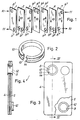
- the plate-shaped heat exchanger seen separated in Figure 1, consists of a number of pressed heat exchange plates 1, 2, 3 ...7, having through-going holes 81, 82, 83 ...87 and 91, 92, 93..97.
- the heat exchange plates are assembled in twos by brazing along the edge of two opposite holes 8 and 9 so that two closed, parallel flow channels 10 and 11 are formed.
- the media of the flow channels 10 and 11 flow alternately through every other interspace between the plates.
- a cold flow of liquid or gas passing through one channel may be heated by means of a hot flow of liquid or gas flowing through the other channel.
- the flow channel 10 consists of the interspaces between the plates 1, 2, 3, 4 and 5 and 6 of the through-going holes 81, 82...87.
- the hole 81 forms the inlet of the flow channel 10 into the plate-shaped heat exchanger
- the holes 82-83 and 84-85 brazed peripherally together in pairs form the passages between the interspaces of the plates
- the holes 86-87 brazed peripherally together form the outlet of the flow channel 10 from the plate-shaped heat exchanger.
- the flow channel 11 wherein the medium flows in the opposite direction relative to the medium of the flow channel 10 consists of the interspaces between the plates 2-3, 4-5 and 6-7, of the inlet hole 97, and of the holes 91-92, 93-94 and 95-96 brazed peripherally together which partly form the passages between the interspaces of the plates and the outlet from the plate-shaped heat exchanger.
- FIG. 2 shows a perspective view of a holding means 12 in accordance with the invention.
- the holding means 12 has the shape of a cut ring with an outwardly turning U-shaped cross-section from the central portion thereof and which is adapted for position about the hole edges. It is e.g. made from a U-shaped band steel or the like which is cut and shaped into a ring.
- the ring is made as precisely as possible relative to the holes and its ends 13 and 14 press against each other when the ring is positioned about the hole edges. Thereby, it is ensured that the ring is locked about the hole edges simultaneously with centering of the holes.
- the heat exchanger plates and the holding means are preferably made of materials having the same capability of being brazed and approximately the same heat expansion coefficient to prevent that the ring is loosened during the brazing process. Most often, the parts are made of stainless steel to avoid corrosion of the plate-shaped heat exchanger.
- the holding means 12 is positioned about the edges of two oppositely arranged holes 8 or 9 in their respective heat exhange plate as shown in Figures 3 and 4.
- the holding means is locked by pressing its ends 13 and 14 against each other.
- the holding means is able to keep the heat exchange plates so tightly together that during the brazing process suitable capillary gaps (i.e. often less than 1/10 mm) are available for the brazing metal between the plates, respectively between plate and ring.
- brazing metal may be put into the joints.
- the brazing metal is provided before the positioning of the holding means and, in particular, that the holding means are used for prepositioning of the brazing metal.
- the plate-shaped heat exchanger thus assembled and provided with brazing metal is placed in a brazing oven wherein it is heated relatively slowly in order to avoid that the heat exchange plates buckle considerably relative to each other.
- the holding means plays an important part since they prevent dissimilar heat expansion of the heat exchange plates to a high degree, the holding means locking and centering the plates relative to each other.
- the brazing metal melts, it does not only disperse in the available capillary gap between the plates, but also fills the gaps between the plates and the holding means.
- the holding means 12 thus forms an additional seal and enforcement along the edges of the holes 8 or 9.
- the heat exchanger plates may also be brazed at their outer edges to form the water and gas tight plate interspaces.
- Plate-shaped heat exchangers assembled with said holding means have been brazed in an oven having a protective atmosphere and with the possibility of controlling the speed of heating so as to cause no deformation of the plates.
Landscapes
- Engineering & Computer Science (AREA)
- Mechanical Engineering (AREA)
- Physics & Mathematics (AREA)
- Optics & Photonics (AREA)
- Thermal Sciences (AREA)
- General Engineering & Computer Science (AREA)
- Heat-Exchange Devices With Radiators And Conduit Assemblies (AREA)
Applications Claiming Priority (2)
| Application Number | Priority Date | Filing Date | Title |
|---|---|---|---|
| DK486/88 | 1988-01-29 | ||
| DK48688A DK157785C (da) | 1988-01-29 | 1988-01-29 | Fremgangmaade til planparallel sammenfoejning ved lodning af metalplader, navnlig til fremstilling af en pladevarmeveksler samt holdeorgan dertil |
Publications (2)
| Publication Number | Publication Date |
|---|---|
| EP0400043A1 EP0400043A1 (en) | 1990-12-05 |
| EP0400043B1 true EP0400043B1 (en) | 1993-03-24 |
Family
ID=8094107
Family Applications (1)
| Application Number | Title | Priority Date | Filing Date |
|---|---|---|---|
| EP19890902374 Expired - Lifetime EP0400043B1 (en) | 1988-01-29 | 1989-01-26 | Process for coparallel joining of plate metal by brazing, in particular for preparing a plate-shaped heat exchanger, and holding means therefor |
Country Status (3)
| Country | Link |
|---|---|
| EP (1) | EP0400043B1 (da) |
| DK (1) | DK157785C (da) |
| WO (1) | WO1989007034A1 (da) |
Families Citing this family (7)
| Publication number | Priority date | Publication date | Assignee | Title |
|---|---|---|---|---|
| WO1993012345A1 (en) * | 1991-12-11 | 1993-06-24 | Fredric Lange | Modular structural framing system |
| US5584156A (en) * | 1993-07-16 | 1996-12-17 | Lange; Fredric | Modular structural framing system |
| US5588274A (en) * | 1993-07-16 | 1996-12-31 | Lange; Fredric | Modular structural framing system |
| US5706622A (en) * | 1994-06-10 | 1998-01-13 | Lange; Fredric | Modular structural framing system |
| FR2761626B1 (fr) * | 1997-04-03 | 1999-06-04 | Renault | Procede d'assemblage par soudage de pieces de tolerie |
| WO2004042420A2 (de) * | 2002-11-05 | 2004-05-21 | Hartmann, Helga | Anordnung zum löten eines aus einer anzahl von segmentblechen fügbaren metallblocks mit als träger für lotmaterial dienenden fixierungselementen |
| CN106736200B (zh) * | 2017-03-17 | 2018-06-12 | 卡尔迈耶(中国)有限公司 | 经编机左墙板定位焊装置及其使用方法 |
Family Cites Families (1)
| Publication number | Priority date | Publication date | Assignee | Title |
|---|---|---|---|---|
| DE2611832A1 (de) * | 1976-03-19 | 1977-09-22 | Linde Ag | Verfahren und vorrichtung zum flussmittellosen loeten |
-
1988
- 1988-01-29 DK DK48688A patent/DK157785C/da active
-
1989
- 1989-01-26 EP EP19890902374 patent/EP0400043B1/en not_active Expired - Lifetime
- 1989-01-26 WO PCT/DK1989/000012 patent/WO1989007034A1/en not_active Ceased
Also Published As
| Publication number | Publication date |
|---|---|
| DK157785C (da) | 1990-09-10 |
| DK48688A (da) | 1989-07-30 |
| DK48688D0 (da) | 1988-01-29 |
| EP0400043A1 (en) | 1990-12-05 |
| WO1989007034A1 (en) | 1989-08-10 |
| DK157785B (da) | 1990-02-19 |
Similar Documents
| Publication | Publication Date | Title |
|---|---|---|
| AU686184B2 (en) | Plate heat exchanger | |
| EP1136782B1 (en) | Plate type heat exchanger and method of manufacturing the heat exchanger | |
| EP0069808B1 (en) | Thin sheet heat exchanger | |
| US5644840A (en) | Method of producing a plate-type heat exchanger | |
| US20010030043A1 (en) | Brazed plate heat exchanger utilizing metal gaskets and method for making same | |
| US7234511B1 (en) | Modular heat exchanger having a brazed core and method for forming | |
| US3710473A (en) | Method of manufacturing a heat exchanger | |
| AU739681B2 (en) | Three circuit plate heat exchanger | |
| EP2084481B1 (en) | Plate heat exchanger | |
| EP0877908B1 (en) | Plate fin heat exchanger | |
| US4687053A (en) | Heat exchanger panel and manufacturing method thereof | |
| US8167029B2 (en) | Plate heat exchanger | |
| EP1094291A2 (en) | Plate heat exchanger | |
| US4431050A (en) | Stacked-plate heat exchanger made of identical corrugated plates | |
| CA2104905A1 (en) | All-Welded Plate Heat Exchanger | |
| EP0400043B1 (en) | Process for coparallel joining of plate metal by brazing, in particular for preparing a plate-shaped heat exchanger, and holding means therefor | |
| CA1138423A (en) | Plate heat exchanger | |
| CA1313182C (en) | In tank oil cooler | |
| EP0984239A3 (en) | Heat exchanger | |
| JP2531398B2 (ja) | プレ−トフィン型熱交換器及びその製造方法 | |
| EP0612396B1 (en) | In tank oil cooler | |
| US3515208A (en) | Heat exchanger construction | |
| WO2001048433A1 (en) | Plate heat exchanger | |
| EP4607133A1 (en) | Method for the assembly of a plate package of a plate heat exchanger and a plate heat exchanger | |
| JPS62230474A (ja) | 熱交換器 |
Legal Events
| Date | Code | Title | Description |
|---|---|---|---|
| PUAI | Public reference made under article 153(3) epc to a published international application that has entered the european phase |
Free format text: ORIGINAL CODE: 0009012 |
|
| 17P | Request for examination filed |
Effective date: 19900717 |
|
| AK | Designated contracting states |
Kind code of ref document: A1 Designated state(s): BE DE FR GB IT LU NL SE |
|
| 17Q | First examination report despatched |
Effective date: 19910731 |
|
| GRAA | (expected) grant |
Free format text: ORIGINAL CODE: 0009210 |
|
| AK | Designated contracting states |
Kind code of ref document: B1 Designated state(s): BE DE FR GB IT LU NL SE |
|
| PG25 | Lapsed in a contracting state [announced via postgrant information from national office to epo] |
Ref country code: IT Free format text: LAPSE BECAUSE OF FAILURE TO SUBMIT A TRANSLATION OF THE DESCRIPTION OR TO PAY THE FEE WITHIN THE PRE;WARNING: LAPSES OF ITALIAN PATENTS WITH EFFECTIVE DATE BEFORE 2007 MAY HAVE OCCURRED AT ANY TIME BEFORE 2007. THE CORRECT EFFECTIVE DATE MAY BE DIFFERENT FROM THE ONE RECORDED.SCRIBED TIME-LIMIT Effective date: 19930324 Ref country code: SE Effective date: 19930324 Ref country code: DE Effective date: 19930324 Ref country code: NL Effective date: 19930324 Ref country code: FR Effective date: 19930324 Ref country code: BE Effective date: 19930324 |
|
| REF | Corresponds to: |
Ref document number: 68905594 Country of ref document: DE Date of ref document: 19930429 |
|
| EN | Fr: translation not filed | ||
| NLV1 | Nl: lapsed or annulled due to failure to fulfill the requirements of art. 29p and 29m of the patents act | ||
| PG25 | Lapsed in a contracting state [announced via postgrant information from national office to epo] |
Ref country code: GB Effective date: 19940126 |
|
| PLBE | No opposition filed within time limit |
Free format text: ORIGINAL CODE: 0009261 |
|
| STAA | Information on the status of an ep patent application or granted ep patent |
Free format text: STATUS: NO OPPOSITION FILED WITHIN TIME LIMIT |
|
| PG25 | Lapsed in a contracting state [announced via postgrant information from national office to epo] |
Ref country code: LU Free format text: LAPSE BECAUSE OF NON-PAYMENT OF DUE FEES Effective date: 19940131 |
|
| 26N | No opposition filed | ||
| GBPC | Gb: european patent ceased through non-payment of renewal fee |
Effective date: 19940126 |