EP0400045B1 - Articulation de prothese - Google Patents
Articulation de prothese Download PDFInfo
- Publication number
- EP0400045B1 EP0400045B1 EP89902459A EP89902459A EP0400045B1 EP 0400045 B1 EP0400045 B1 EP 0400045B1 EP 89902459 A EP89902459 A EP 89902459A EP 89902459 A EP89902459 A EP 89902459A EP 0400045 B1 EP0400045 B1 EP 0400045B1
- Authority
- EP
- European Patent Office
- Prior art keywords
- component
- joint
- bearing surface
- concave
- portions
- Prior art date
- Legal status (The legal status is an assumption and is not a legal conclusion. Google has not performed a legal analysis and makes no representation as to the accuracy of the status listed.)
- Expired - Lifetime
Links
- 230000033001 locomotion Effects 0.000 claims abstract description 34
- 210000000629 knee joint Anatomy 0.000 claims abstract description 18
- 210000002303 tibia Anatomy 0.000 claims abstract description 16
- 210000000689 upper leg Anatomy 0.000 claims description 12
- 238000005096 rolling process Methods 0.000 claims description 7
- 230000003993 interaction Effects 0.000 claims description 2
- 238000010276 construction Methods 0.000 description 10
- 230000007704 transition Effects 0.000 description 8
- 210000004417 patella Anatomy 0.000 description 7
- 210000000988 bone and bone Anatomy 0.000 description 6
- 210000003127 knee Anatomy 0.000 description 6
- 229910052751 metal Inorganic materials 0.000 description 6
- 239000002184 metal Substances 0.000 description 6
- 239000004033 plastic Substances 0.000 description 6
- 229920003023 plastic Polymers 0.000 description 6
- 239000000463 material Substances 0.000 description 4
- 238000001356 surgical procedure Methods 0.000 description 4
- 238000013459 approach Methods 0.000 description 2
- 230000008901 benefit Effects 0.000 description 2
- 230000013011 mating Effects 0.000 description 2
- 238000000034 method Methods 0.000 description 2
- 230000006641 stabilisation Effects 0.000 description 2
- 238000011105 stabilization Methods 0.000 description 2
- 229910000684 Cobalt-chrome Inorganic materials 0.000 description 1
- 229910001069 Ti alloy Inorganic materials 0.000 description 1
- RTAQQCXQSZGOHL-UHFFFAOYSA-N Titanium Chemical compound [Ti] RTAQQCXQSZGOHL-UHFFFAOYSA-N 0.000 description 1
- 229920010741 Ultra High Molecular Weight Polyethylene (UHMWPE) Polymers 0.000 description 1
- 239000004699 Ultra-high molecular weight polyethylene Substances 0.000 description 1
- 229910000756 V alloy Inorganic materials 0.000 description 1
- 239000011324 bead Substances 0.000 description 1
- 230000008859 change Effects 0.000 description 1
- 239000000788 chromium alloy Substances 0.000 description 1
- 230000009194 climbing Effects 0.000 description 1
- 239000010952 cobalt-chrome Substances 0.000 description 1
- 230000006835 compression Effects 0.000 description 1
- 238000007906 compression Methods 0.000 description 1
- 230000000694 effects Effects 0.000 description 1
- 210000002310 elbow joint Anatomy 0.000 description 1
- 238000002513 implantation Methods 0.000 description 1
- 238000011065 in-situ storage Methods 0.000 description 1
- 238000013150 knee replacement Methods 0.000 description 1
- 210000001699 lower leg Anatomy 0.000 description 1
- 230000007246 mechanism Effects 0.000 description 1
- 238000012986 modification Methods 0.000 description 1
- 230000004048 modification Effects 0.000 description 1
- 210000000426 patellar ligament Anatomy 0.000 description 1
- 230000003014 reinforcing effect Effects 0.000 description 1
- 230000000630 rising effect Effects 0.000 description 1
- 229910052719 titanium Inorganic materials 0.000 description 1
- 239000010936 titanium Substances 0.000 description 1
- -1 titanium-aluminum-vanadium Chemical compound 0.000 description 1
- 229920000785 ultra high molecular weight polyethylene Polymers 0.000 description 1
- 239000000602 vitallium Substances 0.000 description 1
Images


Classifications
-
- A—HUMAN NECESSITIES
- A61—MEDICAL OR VETERINARY SCIENCE; HYGIENE
- A61F—FILTERS IMPLANTABLE INTO BLOOD VESSELS; PROSTHESES; DEVICES PROVIDING PATENCY TO, OR PREVENTING COLLAPSING OF, TUBULAR STRUCTURES OF THE BODY, e.g. STENTS; ORTHOPAEDIC, NURSING OR CONTRACEPTIVE DEVICES; FOMENTATION; TREATMENT OR PROTECTION OF EYES OR EARS; BANDAGES, DRESSINGS OR ABSORBENT PADS; FIRST-AID KITS
- A61F2/00—Filters implantable into blood vessels; Prostheses, i.e. artificial substitutes or replacements for parts of the body; Appliances for connecting them with the body; Devices providing patency to, or preventing collapsing of, tubular structures of the body, e.g. stents
- A61F2/02—Prostheses implantable into the body
- A61F2/30—Joints
- A61F2/38—Joints for elbows or knees
- A61F2/3836—Special connection between upper and lower leg, e.g. constrained
- A61F2/384—Special connection between upper and lower leg, e.g. constrained hinged, i.e. with transverse axle restricting the movement
- A61F2/385—Special connection between upper and lower leg, e.g. constrained hinged, i.e. with transverse axle restricting the movement also provided with condylar bearing surfaces
-
- A—HUMAN NECESSITIES
- A61—MEDICAL OR VETERINARY SCIENCE; HYGIENE
- A61F—FILTERS IMPLANTABLE INTO BLOOD VESSELS; PROSTHESES; DEVICES PROVIDING PATENCY TO, OR PREVENTING COLLAPSING OF, TUBULAR STRUCTURES OF THE BODY, e.g. STENTS; ORTHOPAEDIC, NURSING OR CONTRACEPTIVE DEVICES; FOMENTATION; TREATMENT OR PROTECTION OF EYES OR EARS; BANDAGES, DRESSINGS OR ABSORBENT PADS; FIRST-AID KITS
- A61F2/00—Filters implantable into blood vessels; Prostheses, i.e. artificial substitutes or replacements for parts of the body; Appliances for connecting them with the body; Devices providing patency to, or preventing collapsing of, tubular structures of the body, e.g. stents
- A61F2/02—Prostheses implantable into the body
- A61F2/30—Joints
- A61F2/38—Joints for elbows or knees
- A61F2/3868—Joints for elbows or knees with sliding tibial bearing
-
- A—HUMAN NECESSITIES
- A61—MEDICAL OR VETERINARY SCIENCE; HYGIENE
- A61F—FILTERS IMPLANTABLE INTO BLOOD VESSELS; PROSTHESES; DEVICES PROVIDING PATENCY TO, OR PREVENTING COLLAPSING OF, TUBULAR STRUCTURES OF THE BODY, e.g. STENTS; ORTHOPAEDIC, NURSING OR CONTRACEPTIVE DEVICES; FOMENTATION; TREATMENT OR PROTECTION OF EYES OR EARS; BANDAGES, DRESSINGS OR ABSORBENT PADS; FIRST-AID KITS
- A61F2/00—Filters implantable into blood vessels; Prostheses, i.e. artificial substitutes or replacements for parts of the body; Appliances for connecting them with the body; Devices providing patency to, or preventing collapsing of, tubular structures of the body, e.g. stents
- A61F2/02—Prostheses implantable into the body
- A61F2/30—Joints
- A61F2/38—Joints for elbows or knees
- A61F2/3886—Joints for elbows or knees for stabilising knees against anterior or lateral dislocations
-
- A—HUMAN NECESSITIES
- A61—MEDICAL OR VETERINARY SCIENCE; HYGIENE
- A61F—FILTERS IMPLANTABLE INTO BLOOD VESSELS; PROSTHESES; DEVICES PROVIDING PATENCY TO, OR PREVENTING COLLAPSING OF, TUBULAR STRUCTURES OF THE BODY, e.g. STENTS; ORTHOPAEDIC, NURSING OR CONTRACEPTIVE DEVICES; FOMENTATION; TREATMENT OR PROTECTION OF EYES OR EARS; BANDAGES, DRESSINGS OR ABSORBENT PADS; FIRST-AID KITS
- A61F2/00—Filters implantable into blood vessels; Prostheses, i.e. artificial substitutes or replacements for parts of the body; Appliances for connecting them with the body; Devices providing patency to, or preventing collapsing of, tubular structures of the body, e.g. stents
- A61F2/02—Prostheses implantable into the body
- A61F2/30—Joints
- A61F2/38—Joints for elbows or knees
- A61F2/3877—Patellae or trochleae
-
- A—HUMAN NECESSITIES
- A61—MEDICAL OR VETERINARY SCIENCE; HYGIENE
- A61F—FILTERS IMPLANTABLE INTO BLOOD VESSELS; PROSTHESES; DEVICES PROVIDING PATENCY TO, OR PREVENTING COLLAPSING OF, TUBULAR STRUCTURES OF THE BODY, e.g. STENTS; ORTHOPAEDIC, NURSING OR CONTRACEPTIVE DEVICES; FOMENTATION; TREATMENT OR PROTECTION OF EYES OR EARS; BANDAGES, DRESSINGS OR ABSORBENT PADS; FIRST-AID KITS
- A61F2310/00—Prostheses classified in A61F2/28 or A61F2/30 - A61F2/44 being constructed from or coated with a particular material
- A61F2310/00005—The prosthesis being constructed from a particular material
- A61F2310/00011—Metals or alloys
- A61F2310/00023—Titanium or titanium-based alloys, e.g. Ti-Ni alloys
-
- A—HUMAN NECESSITIES
- A61—MEDICAL OR VETERINARY SCIENCE; HYGIENE
- A61F—FILTERS IMPLANTABLE INTO BLOOD VESSELS; PROSTHESES; DEVICES PROVIDING PATENCY TO, OR PREVENTING COLLAPSING OF, TUBULAR STRUCTURES OF THE BODY, e.g. STENTS; ORTHOPAEDIC, NURSING OR CONTRACEPTIVE DEVICES; FOMENTATION; TREATMENT OR PROTECTION OF EYES OR EARS; BANDAGES, DRESSINGS OR ABSORBENT PADS; FIRST-AID KITS
- A61F2310/00—Prostheses classified in A61F2/28 or A61F2/30 - A61F2/44 being constructed from or coated with a particular material
- A61F2310/00005—The prosthesis being constructed from a particular material
- A61F2310/00011—Metals or alloys
- A61F2310/00029—Cobalt-based alloys, e.g. Co-Cr alloys or Vitallium
Definitions
- This invention relates to improved prosthetic joints and in particular to improved prosthetic knee joints.
- the features of the preamble of Claim 1 are known from US-A-4 298 992.
- Flexion and extension of the normal human knee involves complex movements of three bones: the femur, the tibia, and the patella.
- the distal end of the femur and the proximal end of the tibia rotate and glide relative to one another, with the center of rotation of the joint moving posteriorly over the condyles of the femur; during extension, the tibia and femur follow the reverse path, with the center of rotation now moving anteriorly as the joint is extended.
- the patella moves over the surface of the femoral condyles, while remaining at a relatively constant distance from the tubercle of the tibia through the attachment of the patella to the tibia by the patellar ligament.
- a patellar prosthesis e.g., a spherically-domed or conical plastic button, is normally attached to the posterior surface of the patella to serve as an interface between the patella bone and the femoral prosthesis.
- Efforts have been made to produce prosthetic joints which function in a manner similar to the natural knee. Specifically, a number of mechanisms have been proposed for producing posterior movement of the femoral component relative to the tibial component (femoral roll-back on the tibia) as the joint is flexed.
- Walker et al. U.S. Pat. No. 4,209,861 discloses a prosthetic knee joint wherein guiding surfaces on the femoral and tibial components are used to induce posterior movement on the tibial component of the contact area between the components as the knee is progressively flexed.
- the posterior movement takes place through a major portion of the flexion of the joint Burstein et al., U.S. Pat. No. 4,298,992, shows an alternate construction in which the femoral component moves posteriorly relative to the tibial component at or near full flexion. See also Deane, U.S. Pat. No. 3,840,905.
- Efforts have also been made to improve the functioning of patellar prostheses. See, for example Pappas et al., U.S. Pat. No. 4,470,158, Buechel et al., U.S. Pat. No. 4,309,778, and Buechel et al., U.S. Pat. No 4,340,978.
- the anterior surfaces of femoral components have been provided with concave recesses for receiving patellar prostheses when the joint is at or near its fully extended position. See, for example, Forte et al., U.S. Pat. No. 4,353,135, and Walker, U.S. Pat. No. 4,209,861.
- the distal surfaces of femoral components have included tracks for receiving the patellar prosthesis when the joint is flexed.
- the surfaces which engage the patellar prosthesis on these prior art tracks have been convexly shaped. Indeed, discontinuities in the slope of the prosthesis' outer surface have existed at the intersection between the concave recess of the anterior surface and the convex track of the distal surface.
- Prostheses employing convex tracks have suffered a number of disadvantages.
- the track and the patellar prosthesis have only made point contact.
- prosthetic knee joints are subject to high loads when flexed, i.e., when the patellar prosthesis is in contact with the distal track. This combination of high loads and point contact has resulted in high wear rates for the patellar prosthesis.
- patellar prostheses consisting of a plastic bearing mounted on a metal backing plate, complete wear through of the bearing so as to cause the metal plate and the metal femoral component to grind against one another in situ, has been observed.
- the discontinuity in the outer surface of the femoral prosthesis at the intersection between the concave recess and the convex track has also contributed to wearing of the patellar prosthesis and has degraded the overall smooth operation of the prosthesis.
- the Forte et al. patent referred to above discloses a construction for a patellar prosthesis which can achieve line contact with a convex track.
- This construction employs a complex patellar button geometry which must be precisely aligned with the femoral prosthesis during the surgical procedure for the system to operate properly.
- the existing patellar prosthesis is normally not replaced.
- Most existing patellar prostheses are of the conical or spherically-domed button type.
- the Forte et al construction like the rest of the prior art constructions, only provides point contact when used with such spherically-domed or conical patellar prostheses.
- a specific object of the invention is to provide a prosthetic joint composed of two components, e.g. a femoral component and a tibial component, wherein the first component translates relative to the second component as the joint moves from its extended to its flexed position and wherein the area of contact between the bearing surfaces of the first and second components is large and, in particular, is large when the joint is flexed.
- Another object of the invention in its preferred form, is to provide a femoral prosthesis whose distal surface is configured to provide line contact, as opposed to point contact, with a patellar prosthesis, including line contact with the spherically-domed and conical button-type prostheses which are typically encountered in revision surgery.
- US-A-4 634 444 discloses a prosthetic joint which provides flexion movement between two bones between their flexed and their extended positions.
- the present invention as defined in claim 1, has additional curved bearing areas contiguous with the first main bearing areas so as to form a continuation thereof with a smaller curvature (larger radius) than the first bearing surfaces but such as to provide line bearing rolling contact during initial flexure of the joint followed by sliding area bearing contact during continued flexure when the loading forces to be supported by the joint are greater, control of the rolling movement being assisted during the minor portion of the joint's motion by interaction between cam means on the first and second components.
- the invention provides an artificial joint which has an extended position, an intermediate position and a flexed position.
- the motion of the joint includes a minor segment and a major segment, the minor segment comprising rolling movement between the extended and the intermediate positions and the major segment comprising sliding movement between the intermediate and the flexed positions.
- the joint comprises two components e.g. for a knee prostheses, the femoral component and the tibial component.
- Each component includes a bearing surface and a cam member.
- Each bearing surface includes a first portion and a second portion, the first portions being in engagement with one another during the minor segment of the joint's motion, and the second portions being in engagement with one another during the major segment of the joint's motion.
- the second portions comprise large area, stepped bearing surfaces of the type disclosed in U.S. Pat. No. 4,634,444, referred to above, the pertinent portions of which are incorporated herein by reference.
- the motion of the joint comprises rotation about an axis of flexion.
- the rotation takes place through sliding of the bearing surfaces of the second portions relative to one another.
- the cam members on the first and second components interact with one another during the minor segment of the joint's motion.
- the cam members permit the first portions of the bearing surfaces to roll relative to one another as the joint moves between its extended and intermediate positions.
- the area of contact between the second portions of the bearing surfaces is greater than the area of contact between the first portions.
- a femoral prosthesis whose outer surface has an anterior portion and a distal portion.
- the anterior portion includes a recess for engagement with a patellar prosthesis
- the distal portion includes a track for the same purpose.
- the track is composed of two rails which intersect the recess.
- the surface of each of the rails has a cross-sectional contour in a direction transverse to the longitudinal axis of the rail which is 1) either a straight line or a concave curve, 2) constant along the length of the rail, and 3) matches the contour of the surface of the recess at the intersection between the rail and the recess.
- the patellar prosthesis moves smoothly over both the anterior and distal surfaces of the femoral prosthesis, including the transition between those surfaces. Moreover, the patellar prosthesis makes line contact with the distal surface of the femoral prosthesis.
- the contour of the rails is a portion of a straight line
- line contact with conical patellar buttons is achieved
- line contact with spherically-domed patellar buttons is achieved.
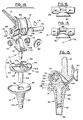
- Figure 1 is a perspective, exploded view of a semi-constrained artificial knee joint constructed in accordance with the present invention.
- Figure 2 is a side view of the tibial plateau component of the joint of Figure 1.
- Figure 3 is a view of the anterior surface of the femoral component of the joint of Figure 1 showing the engagement of the patellar component of the joint of Figure 1 with the anterior surface.
- Figure 4 is a view of the anterior surface of the femoral component of the joint of Figure 1 showing the engagement of the patellar component with the distal surface of the femoral component.
- Figure 5 is a view of the distal surface of the femoral component of the joint of Figure 1 shoving the engagement of the patellar component with the anterior surface.
- Figure 6 is a cross-sectional view along lines 6-6 in Figure 4.
- Figures 7-10 are side views of the joint of Figure 1 at flexion angles of 0°, 16°, 45°, and 120°, respectively.
- Figure 11 is a side view of the joint of Figure 1 at a hyperextended angle of -6°.
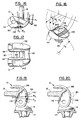
- Figures 12 and 13 compare the engagement between the patellar and femoral components achieved with the present invention (Figure 13) with that achieved with prior art prostheses ( Figure 12).
- Figure 14 is a perspective, exploded view of a constrained artificial knee joint employing a patella tracking system as may be used with the knee joint of the present invention.
- Figure 15 is a cross-sectional view of the joint of Figure 14 along the midline of the prosthesis.
- Figure 16 is a side view of the femoral and patellar components of the joint of Figure 14.
- Figure 17 is a view of the distal surface of the femoral component of the joint of Figure 14 showing the engagement of the patellar component with the distal surface.
- Figure 18 is a perspective view of a patellar prosthesis having a saddle-shaped surface.
- Figures 19 and 20 are sectional views in sagittal planes comparing the engagement of the femoral component of the joint of Figure 14 with a spherically-domed patellar button (Figure 20) and with the patellar prosthesis of Figure 18 ( Figure 19).
- FIG. 1 an exploded view of a semi-constrained artificial knee joint constructed in accordance with the present invention.
- the joint includes a femoral component 10 and a tibial component 13 comprising tibial plateau component 12 and tibial sleeve component 14.
- the joint is designed to smoothly interact with patellar prosthesis 80.
- Femoral component 10 and tibial plateau component 12 respectively carry mating convex bearing surface 20 and concave bearing surface 34 (see Figure 1).
- femoral convex bearing surface 20 is composed of part 20a described by radius R1, part 20b described by radius R2, and part 20c described by radius R3.
- Femoral convex surface 20 also includes part 20d described by radius R4.
- Radius R4 has the same center as radius R3, and therefore surface 20d is concentric with surface 20c.
- Part 20b is also referred to herein as the first portion of convex bearing surface 20; the combination of parts 20c and 20d are also referred to herein as the second portion of convex bearing surface 20.
- tibial concave bearing surface 34 is composed of part 34a described by radius R1, part 34b which may be flat or concave with a radius greater than radius R2 of femoral component 10, and part 34c described by radius R3. Tibial concave surface 34 also includes part 34d described by radius R4. Radius R4 has the same center as radius R3, and therefore surface 34d is concentric with surface 34c. Part 34b is also referred to herein as the first portion of concave bearing surface 34; the combination of parts 34c and 34d are also referred to herein as the second portion of concave bearing surface 34.
- each of parts 20a, 20b, and 20c, and parts 34a, 34b, and 34c are composed of two spaced-apart sections.
- these stepped bearings extend across the full width of the prosthesis so as to provide a large, wear-resistant bearing surface for flexion motions of the joint.
- parts 20c and 20d i.e., the second portion of convex bearing surface 20, and parts 34c and 34d, i.e., the second portion of concave bearing surface 34, are surfaces of revolution, i.e., cylindrical in shape, although other bearing contours can be used in the practice of the invention.
- the second portion of concave bearing surface 34 encompasses less than one-half of the second portion of convex bearing surface 20.
- the second portions engage each other over an angle A, which for the embodiment shown is approximately 15°.
- the spaced-apart sections of part 34c are connected to part 34d by walls 44.
- the spaced-apart section of part 20c are connected to part 20d by walls 28.
- the presence of these walls stabilizes the assembled joint against dislocations along the axis of rotation of the second portions of bearings 20 and 34.
- the engagement of the walls limits the lateral motion of surfaces 20 and 34 with respect to one another.
- this stabilization is achieved without sacrificing the overall width of the bearing surfaces, as would occur with other modes of lateral stabilization known in the art, such as, through the use of a post or the like between two laterally separated bearing surfaces.
- the outer sections of parts 20c and 34c have equal radii of curvature, and those radii of curvature are larger than the radius of curvature of parts 20d and 34d. It is to be understood that the bearing surfaces can have radii of curvature other than those shown, provided that the radii are such that their differences produce walls 28 and 44 of sufficient height to restrain the joint against lateral dislocations.
- tibial plateau component 12 also includes cam means 41.
- femoral component 10 includes cam means 43.
- Cam means 41 is located between the spaced-apart sections of part 34b and comprises an extension of part 34d.
- Cam means 43 is located between the spaced-apart sections of part 20b and comprises an extension of part 20d.
- Cam means 41 is connected to part 34b by extensions of walls 44.
- cam means 43 is connected to part 20b by extensions of walls 28.
- cam means 41 and 43 The operation of cam means 41 and 43 is illustrated in Figures 7-10, where Figure 7 shows the joint in its extended position, Figure 8 shows the joint in its intermediate position, and Figures 9 and 10 show the joint at flexion angles of 45° and 120°, respectively.
- parts 20b and 34b i.e., the first portions of surfaces 20 and 34, are in engagement in the joint's extended position ( Figure 7) and roll relative to one another as the joint moves from its extended position to its intermediate position ( Figure 8).
- the theoretical contact between parts 20b and 34b during this rolling is line contact.
- Cam means 41 and 43 interact during this portion of the joint's motion to allow and control the rolling between the bearing surfaces. The natural forces in the knee tend to keep the cam means in contact through the minor segment of the joint's motion.
- the motion of the joint when these second portions of surfaces 20 and 34 are in engagement consists of simple rotation of the joint about the axis defined by the common center of radii R3 and R4. The second portions slide on one another during this rotation.
- the transition between the first and second portions of the bearing surfaces is performed early in the flexion of the joint.
- the transition takes place at a flexion angle of about 16° from the extended position of the joint.
- the motion of the joint thus consists of a minor segment from 0° to about 16°, and a major segment from about 16° to the flexed position of the joint, e.g., 100° to 120°, with the major segment being about 5 times greater than the minor segment.
- transition point between the first and second portions of the bearing surfaces can of course be set at flexion angles either greater than or less than 16°. In general, the transition point should occur at a flexion angle of less than about 30° in order to obtain the full benefits of the enhanced bearing surface contact area provided by the engagement of the second portions.
- the joint of Figure 1 can also be hyperextended.
- the amount of hyperextension permitted is determined by the engagement of surface 72 on femoral component 10 (see Figure 6) with surface 70 on tibial plateau 12 (see Figure 2).
- Radius R1 of femoral surface 20a also comes into contact with radius R1 of tibial surface 34a which further inhibits hyperextension.
- Figure 11 shows the joint in its fully hyperextended condition. For the joint shown, the hyperextension is limited to -6°. Greater or lesser amounts of hyperextension can be permitted as desired.
- femoral component 10 In addition to carrying convex bearing surface 20 and cam means 43, femoral component 10 also includes fixation shank 16 which is adapted to be implanted in the patient's femur using standard surgical techniques.
- fixation shank 16 In addition to concave bearing surface 34 and cam means 41, tibial plateau component 12 also includes depending shaft 54 and thrust bearing surface 52. As shown in Figure 2, depending shaft 54 can optionally include metal reinforcing rod 74.
- bearing surface 52 on the bottom of tibial plateau component 12 mates with bearing surface 58, i.e., the top surface of tibial sleeve 14, and depending shaft 54 is received in aperture 56 formed in the body of the tibial sleeve.
- this arrangement of these components allows tibial sleeve 14 to rotate with respect to tibial plateau component 12 as the femur and tibia move from a position of full extension to a position of flexion. This rotation of the tibia about its longitudinal axis during flexion is normally in the range of 10-15°.
- Tibial sleeve component 14 is designed to be implanted in the upper portion of the tibia.
- Various approaches can be employed for this implantation.
- One such approach is that described in PCT Patent Publication No. WO85/03426, entitled “Apparatus for Affixing a Prosthesis to Bone,” which is assigned to the same assignee as this application.
- this technique involves providing tibial sleeve 14 with an outer surface 60 which has been contoured to mate with a portion of the inner surface of the hard bone at the upper end of the tibia.
- the surface is also provided with a geometry 62 designed to transform wedging shear loading to compression loading in the tibial bone.
- femoral component 10 In addition to engaging tibial component 13, femoral component 10 also engages patellar prosthesis 80.
- the anterior surface of the femoral component includes concave recess 82 and the distal surface includes track 84 which intersects the recess.
- Track 84 is composed of rails 88, each of which has a cross-sectional contour in a direction transverse to the longitudinal axis of the rail which is 1) either a straight line or a concave curve, 2) constant along the length of the rail, and 3) matches the contour of the surface of recess 82 at the intersection between the rail and the recess.
- Figure 12 shows the construction used in the prior art wherein the portion of the distal surface of femoral prosthesis 92 which engaged patellar prosthesis 80 is convexly shaped. As shown in this figure, the two prostheses only make point contact at points 90. Such point contact leads to high wear rates for the patellar prosthesis. Also, in such prior art prostheses, distinct slope changes exist at the intersection between the convex surface and the concave recess formed in the prosthesis' anterior surface for receiving the patellar prosthesis.
- curves 94 are portions of a circle having the same radius of curvature R5 as the domed surface of the patellar prosthesis.
- each of curves 94 can have a length, which corresponds to the width of the rail, on the order of 5-6 millimeters.
- the line contact between the patellar prosthesis and the distal surface of the femoral prosthesis results in substantially reduced wear rates in comparison to those achieved with point contact. Also, as can be seen in, for example, Figure 1, the concave contour of rails 88 results in a completely smooth transition between the rails and concave recess 82.
- rails 88 are portions of a straight line instead of being concave.
- recess 82 would preferably be V-shaped, i.e., composed of two inwardly sloping planes, so as to produce a smooth transition between the rails and the recess.
- a patellar prosthesis 96 for use with the present invention which achieves even greater contact with the distal surface of the femoral prosthesis is shown in Figure 18.
- the anterior surface of this prosthesis includes peg 98 for attaching the prosthesis to the posterior surface of the patient's patella.
- the posterior surface of the prosthesis, which engages the femoral prosthesis in the assembled joint, has a saddle shape
- the saddle has a radius of curvature R5 in the medial-lateral direction. This curvature matches the medial-lateral radius of curvature of rails 88 (see Figures 4 and 13), and thus contact like that achieved for a spherically-domed patellar prosthesis is achieved in this direction.
- the saddle has radii of curvature of R2 and R ' 2 , respectively.
- R2 is the radius of curvature of the outer edge of rails 88
- R ' 2 is the radius of curvature of the inner edge of the rail.
- patellar prosthesis 96 will make surface contact throughout areas 104 with rails 88 of the femoral prosthesis when the patellar button is in contact with the R2 section of track 84, which condition exists during the high contact forces created by flexion and weight bearing.
- FIGS 14-20 illustrate a constrained ("hinged") artificial knee joint employing concave rails 88 for engaging either spherically-domed patellar prosthesis 80 or saddle-shaped patellar prosthesis 96.
- tibial plateau 12 carries hinge post 106.
- the tibial plateau includes slot 120 having side walls 122.
- the hinge post is mounted to the tibial plateau by snapping flanges 110 under beads 108 formed in side walls 122.
- Hinge post 106 includes hole 112 for receiving two flanged bearings 114, one from each side.
- the joint is assembled by slipping femoral component 10 over the hinge post to bring bearing surfaces 130 on the femoral component into contact with bearing surfaces 132 on the tibial plateau.
- Hinge pin 116 is then slid through holes 126 in the femoral component and through bearings 114 to assemble the hinge.
- Hinge pin 116 is held in place by means of snap rings 118 which are received in grooves 128.
- the joint of Figures 14-20 has large bearing surfaces which extend across essentially the full width of the joint.
- the bearing surfaces associated with the femoral side of the joint comprise surfaces 130 and lower outer surface 134 of hinge pin 116.
- the corresponding concentric bearings surfaces on the tibial side comprise surfaces 132 and the lower inner surface of bearings 114.
- Hinge pin 116 and femoral component 10 are made from materials having similar wear characteristics, e.g., from titanium or cobalt chromium alloys.
- bearings 114 and tibial plateau 12 are made from materials having similar wear characteristics, e.g., from ultra-high molecular weight polyethylene.
- the concentricity of the bearing surfaces is maintained as those surfaces wear since the wearable components, i.e., the plastic components, are all associated with one side of the joint, e.g., the tibial side, and are all surfaces of revolution about the same center line, while the non-wearable components, i.e., the metal components, are all associated with the other side of the joint, e.g., the femoral side, and are surfaces of revolution about the same center line as the plastic components. Accordingly, as the plastic components wear, the common center line will simply shift, e.g., move towards the tibia, with each of the metal and plastic bearing surfaces remaining concentric to its mating surface.
- Bearing surfaces 130 are located further from the midplane of the joint than bearing surfaces typically used in hinged joints. This change allows rails 88 to be moved far enough apart to provide a stable engagement with the patellar prosthesis. During articulation of the joint, rails 88 ride inside of walls 122 and are received in slot 120. The outside surface of the femoral component 10 includes recesses 142 which engage protuberances 144 at the limit of the extension of the joint.
- Femoral component 10, tibial component 13 and patellar components 80 and 96 can be made out of a variety of biologically compatible, surgically implantable materials.
- a cobalt-chromium-molybdenum alloy such as that described in ASTM F75
- a titanium-aluminum-vanadium alloy such as that described in ASTM F136
- ultra-high molecular weight polyethylene UHMWPE
- hinge post 106, hinge pin 116, and snap rings 118 can be made of cobalt-chrome or titanium alloys.
- Other types and combinations of materials appropriate for use in the artificial joint of the present invention will be evident to persons skilled in the art.
- bearing surfaces have configurations other than those shown herein can be used in the practice of the invention.
- cam means other than those described can be used to permit rolling of the bearing surfaces relative to each other during the minor segment of the joint's motion.
Landscapes
- Health & Medical Sciences (AREA)
- Orthopedic Medicine & Surgery (AREA)
- Heart & Thoracic Surgery (AREA)
- Vascular Medicine (AREA)
- Oral & Maxillofacial Surgery (AREA)
- Transplantation (AREA)
- Engineering & Computer Science (AREA)
- Biomedical Technology (AREA)
- Physical Education & Sports Medicine (AREA)
- Cardiology (AREA)
- Life Sciences & Earth Sciences (AREA)
- Animal Behavior & Ethology (AREA)
- General Health & Medical Sciences (AREA)
- Public Health (AREA)
- Veterinary Medicine (AREA)
- Prostheses (AREA)
- Protection Of Pipes Against Damage, Friction, And Corrosion (AREA)
- Materials For Medical Uses (AREA)
Claims (13)
- Articulation de prothèse pouvant être déplacée entre une position déployée et une position fléchie, ladite articulation comportant :
un premier constituant (10) qui comprend une surface d'appui convexe (20) et un premier moyen à came (43), la surface d'appui convexe (20) possédant une première partie (20b) et une seconde partie (20c), la courbure de la première partie (20b) étant inférieure à la courbure de la seconde partie (20c) ;
un second constituant (13) comprenant une surface d'appui concave (34) et un second moyen à came (41) ;
caractérisée en ce que :
la surface d'appui concave (34) du second constituant (13) possède une première partie (34b) et une seconde partie (34c), la courbure de la première partie (34b) étant inférieure à la courbure de la seconde partie (34c); et
le mouvement de l'articulation est constitué d'un segment mineur s étendant entre la position déployée et une position intermédiaire et un segment majeur s'étendant entre la position intermédiaire et la position fléchie, dans laquelle :
la première partie (20b) de la surface d'appui convexe (20) du premier constituant (10) est en contact avec la première partie (34b) de la surface d'appui concave (34) du second constituant (13) durant le segment mineur du mouvement de l'articulation ;
la seconde partie (20c) de la surface d'appui convexe (20) du premier constituant (10) est en contact avec la seconde partie (34c) de la surface d'appui concave (34) du second constituant (34) durant le segment majeur du déplacement de l'articulation, l'articulation se déplaçant autour d'un axe fixe de flexion lorsque lesdites secondes parties (20c, 34c) sont en contact, ladite flexion se produisant par glissement sans roulement desdites secondes parties (20c, 34c) l'une par rapport à l'autre ; et
les premier (43) et second (41) moyens à came interagissent entre eux durant le segment mineur du mouvement de l'articulation, ladite interaction permettant aux surfaces d'appui convexe (20) et concave (34) de rouler l'une par rapport à l'autre sans glissement sensible lorsque l'articulation se déplace entre ses positions déployée et intermédiaire de sorte que la ligne de contact entre les surfaces d'appui (20, 34) se déplace vers les secondes parties (20c, 34c) des surfaces d'appui. - Articulation de prothèse selon la revendication 1, dans laquelle :
le premier constituant (10) comporte le constituant fémoral d'une articulation de genou de prothèse et le second constituant (13) comporte le constituant tibial d'une articulation de genou de prothèse ;
la première partie (20b) de la surface d'appui convexe (20) du premier constituant (10) est disposée antérieurement et la seconde partie (20c) de cette surface d'appui est située postérieurement lorsque le premier constituant (10) est implanté dans le fémur ; et
la première partie (34b) de la surface d'appui concave (34) du second constituant (13) est située antérieurement et la seconde partie (34c) de cette surface d'appui est située postérieurement lorsque le second constituant (13) est implanté dans le tibia. - Articulation de prothèse selon la revendication 1 ou 2, dans laquelle la surface de contact entre les surfaces d'appui convexe (20) et concave (34) est plus grande lorsque les secondes parties (20c, 34c) sont en contact que lorsque les premières parties (20b, 34b) sont en contact.
- Articulation de prothèse selon la revendication 1, 2 ou 3, dans laquelle les secondes parties (20c, 34c) des surfaces d'appui convexe (20) et concave (34) sont en contact étroit durant ledit segment majeur du mouvement de l'articulation.
- Articulation de prothèse selon la revendication 1, 2, 3 ou 4, dans laquelle le segment mineur du mouvement de l'articulation est inférieur à environ 30°.
- Articulation de prothèse selon la revendication 1, 2, 3, 4 ou 5, dans laquelle :
la surface d'appui convexe (20) du premier constituant (10) possède une troisième partie (20d) ;
la surface d'appui concave (34) du second constituant (13) possède une troisième partie (34d) ; et
les troisièmes parties (20d, 34d) sont en contact étroit durant ledit segment majeur du mouvement de l'articulation. - Articulation de prothèse selon la revendication 6, dans laquelle :
les seconde (20c) et troisième (20d) parties de la surface d'appui convexe (20) du premier constituant (10) constituent une surface en gradins ; et
les seconde (34c) et troisième (34d) parties de la surface d'appui concave (34) du second constituant (13) constituent une surface en gradins. - Articulation de prothèse selon la revendication 6 ou 7, dans laquelle ;
la combinaison des seconde (20c) et troisième (20d) parties de la surface d'appui convexe (20) du premier constituant (10) s'étend sensiblement sur toute la largeur de l'articulation de prothèse ; et
la combinaison des seconde (34c) et troisième (34d) parties de la surface d'appui concave (34) du second constituant (13) s'étend sensiblement sur toute la largeur de l'articulation de prothèse. - Articulation de prothèse selon la revendication 1, 2, 3, 4, 5, 6, 7 ou 8, dans laquelle le premier constituant (10) comporte le constituant fémoral d'une articulation de genou de prothèse et dans laquelle ledit premier constituant (10) comprend un corps ayant une surface extérieure dont une partie est située distalement lorsque le premier constituant (10) est implanté dans le fémur, ladite partie comprenant une piste (84) pour un contact avec une prothèse de rotule (80, 96), ladite piste (84) étant constituée de deux rails (88), le contour en coupe de la surface de chacun des rails (88) dans une direction transversale à l'axe longitudinal du rail (88) étant a) soit une droite rectiligne, soit une courbe concave, et b) constante le long du rail (8).
- Articulation de prothèse selon la revendication 1, 2, 3, 4, 5, 6, 7 ou 8, dans laquelle le premier constituant (10) comporte le constituant fémoral d'une articulation de genou de prothèse et dans laquelle ledit premier constituant (10) comprend un corps ayant une surface extérieure, ladite surface extérieure ayant des première et seconde parties, la première partie étant située antérieurement et la seconde partie étant située distalement lorsque le premier constituant (10) est implanté dans le fémur, la première partie de la surface extérieure comprenant un évidement (82) pour un engagement avec une prothèse de rotule (80, 96), la seconde partie de la surface extérieure comprenant une piste (84) pour un engagement avec ladite prothèse de rotule (80, 96), la piste (84) étant composée de deux rails (88), le contour en coupe de la surface de chacun des rails (88) dans une direction transversale à l'axe longitudinal du rail (88) étant, soit une droite rectiligne, soit une courbe concave, ledit contour en coupe étant constant le long du rail (88), lesdits rails (88) s'étendant depuis ledit évidement (82) et le contour en coupe de la surface de chacun desdits rails (88) étant le contour en coupe de la surface de l'évidement (82) à l'intersection entre le rail (88) et l'évidement (82) de sorte que la surface de chaque rail (88) s'étend continûment dans la surface de l'évidement (82).
- Articulation de prothèse selon la revendication 9 ou 10, dans laquelle le contour en coupe de chacun des rails (88) est concave et est une partie d'un cercle.
- Articulation de prothèse selon la revendication 9, 10 ou 11, comprenant en outre une prothèse de rotule (80) dans laquelle la prothèse de rotule (80) fait contact avec chacun des rails (88) le long d'une ligne (138) transversale à l'axe longitudinal du rail.
- Articulation de prothèse selon la revendication 11, comprenant en outre une prothèse de rotule (96), dans laquelle la prothèse de rotule (96) possède une surface en forme de selle et dans laquelle, pour au moins une partie de la piste (84), la prothèse de rotule (96) fait contact avec chacun des rails (88) sur une surface (140) s'étendant sur la longueur du rail (88).
Priority Applications (1)
| Application Number | Priority Date | Filing Date | Title |
|---|---|---|---|
| EP94112487A EP0627203A3 (fr) | 1988-02-02 | 1989-01-31 | Prothèse articulaire. |
Applications Claiming Priority (3)
| Application Number | Priority Date | Filing Date | Title |
|---|---|---|---|
| US07/151,429 US4888021A (en) | 1988-02-02 | 1988-02-02 | Knee and patellar prosthesis |
| PCT/US1989/000387 WO1989006947A1 (fr) | 1988-02-02 | 1989-01-31 | Articulation de prothese |
| US151429 | 2002-05-20 |
Related Child Applications (1)
| Application Number | Title | Priority Date | Filing Date |
|---|---|---|---|
| EP94112487.7 Division-Into | 1994-08-10 |
Publications (3)
| Publication Number | Publication Date |
|---|---|
| EP0400045A1 EP0400045A1 (fr) | 1990-12-05 |
| EP0400045A4 EP0400045A4 (en) | 1991-04-17 |
| EP0400045B1 true EP0400045B1 (fr) | 1995-05-03 |
Family
ID=22538737
Family Applications (2)
| Application Number | Title | Priority Date | Filing Date |
|---|---|---|---|
| EP89902459A Expired - Lifetime EP0400045B1 (fr) | 1988-02-02 | 1989-01-31 | Articulation de prothese |
| EP94112487A Withdrawn EP0627203A3 (fr) | 1988-02-02 | 1989-01-31 | Prothèse articulaire. |
Family Applications After (1)
| Application Number | Title | Priority Date | Filing Date |
|---|---|---|---|
| EP94112487A Withdrawn EP0627203A3 (fr) | 1988-02-02 | 1989-01-31 | Prothèse articulaire. |
Country Status (7)
| Country | Link |
|---|---|
| US (1) | US4888021A (fr) |
| EP (2) | EP0400045B1 (fr) |
| JP (1) | JP2779857B2 (fr) |
| AT (1) | ATE121925T1 (fr) |
| CA (1) | CA1290899C (fr) |
| DE (1) | DE68922487T2 (fr) |
| WO (1) | WO1989006947A1 (fr) |
Cited By (5)
| Publication number | Priority date | Publication date | Assignee | Title |
|---|---|---|---|---|
| DE102005022576A1 (de) * | 2005-05-09 | 2006-11-16 | Aesculap Ag & Co. Kg | Modular aufgebaute, gekoppelte Knieendoprothese |
| DE102005022584A1 (de) * | 2005-05-09 | 2006-11-23 | Aesculap Ag & Co. Kg | Gekoppelte Knieendoprothese |
| DE102005022583B3 (de) * | 2005-05-09 | 2007-02-01 | Aesculap Ag & Co. Kg | Knieendoprothese |
| US7261740B2 (en) | 2003-10-29 | 2007-08-28 | Wright Medical Technology, Inc. | Tibial knee prosthesis |
| DE102015010221A1 (de) | 2014-09-05 | 2016-03-10 | Carl Haasper | Kniegelenk-Endoprothese |
Families Citing this family (258)
| Publication number | Priority date | Publication date | Assignee | Title |
|---|---|---|---|---|
| USD326156S (en) | 1988-10-11 | 1992-05-12 | Techmedica, Inc. | Knee joint for prosthetic system |
| US5037440A (en) * | 1989-06-06 | 1991-08-06 | Koenig Implant, Inc. | Orthopedic toe implant |
| US5171283A (en) * | 1989-07-11 | 1992-12-15 | Biomedical Engineering Trust | Compound shape rotating bearing |
| US4979957A (en) * | 1989-09-11 | 1990-12-25 | Zimmer, Inc. | Textured prosthetic implant |
| GB2237200B (en) * | 1989-09-27 | 1994-02-23 | Univ London | Knee prosthesis |
| GB9018737D0 (en) | 1990-08-28 | 1990-10-10 | Goodfellow John W | Phosphetic patellar components |
| DE69128961T2 (de) * | 1990-11-14 | 1998-10-08 | Arch Development Corp., Chicago, Ill. | Verbesserte knieprothese mit beweglichem lager |
| DE4038037B4 (de) * | 1990-11-29 | 2010-06-02 | Waldemar Link Gmbh & Co. Kg | Kniegelenkendoprothese |
| US5358527A (en) * | 1991-03-22 | 1994-10-25 | Forte Mark R | Total knee prosthesis with resurfacing and posterior stabilization capability |
| US5236461A (en) * | 1991-03-22 | 1993-08-17 | Forte Mark R | Totally posterior stabilized knee prosthesis |
| US5147406A (en) * | 1991-04-22 | 1992-09-15 | Zimmer, Inc. | Femoral component for a knee joint prosthesis having a modular cam and stem |
| CH689539A5 (de) * | 1991-06-17 | 1999-06-15 | Andre Baehler | Kniegelenkprothese. |
| US5395401A (en) * | 1991-06-17 | 1995-03-07 | Bahler; Andre | Prosthetic device for a complex joint |
| GB9125311D0 (en) * | 1991-11-28 | 1992-01-29 | Biomet Ltd | Prosthetic components |
| US5330534A (en) * | 1992-02-10 | 1994-07-19 | Biomet, Inc. | Knee joint prosthesis with interchangeable components |
| FR2691356B1 (fr) * | 1992-05-20 | 1999-07-23 | Bouvet Jean Claude | Prothese de genou. |
| FR2694185B1 (fr) * | 1992-08-03 | 1994-09-16 | Implants Orthoped Toutes Appli | Elément rotulien pour prothèse de genou. |
| US5658342A (en) * | 1992-11-16 | 1997-08-19 | Arch Development | Stabilized prosthetic knee |
| US5549687A (en) * | 1992-12-10 | 1996-08-27 | Wright Medical Technology, Inc. | Retrofit posterior stabilizing housing implant for replacement knee prosthesis |
| US5255838A (en) * | 1992-12-17 | 1993-10-26 | Zimmer, Inc. | Method of providing a threaded bore in a prosthetic implant |
| GB9305279D0 (en) * | 1993-03-15 | 1993-05-05 | Univ London | Total knee replacement prothesis |
| US5405408A (en) * | 1993-05-14 | 1995-04-11 | Pitkin; Mark R. | Artificial knee having dual flexion action during locomotion |
| FR2710258B1 (fr) * | 1993-09-20 | 1995-12-15 | Medinov Sa | Prothèse du genou. |
| GB9405883D0 (en) * | 1994-03-24 | 1994-05-11 | Corin Medical Ltd | Prosthesis assembly |
| US5549686A (en) * | 1994-06-06 | 1996-08-27 | Zimmer, Inc. | Knee prosthesis having a tapered cam |
| USD374078S (en) | 1994-06-09 | 1996-09-24 | Zimmer, Inc. | Femoral implant |
| GB9415180D0 (en) * | 1994-07-28 | 1994-09-21 | Walker Peter S | Stabilised mobile bearing knee |
| US5824096A (en) * | 1994-12-12 | 1998-10-20 | Biomedical Engineering Trust I | Hinged knee prosthesis with condylar bearing |
| AUPN089495A0 (en) * | 1995-02-03 | 1995-03-02 | Denupo Pty. Ltd. | Knee prosthesis |
| FR2734709B1 (fr) * | 1995-05-31 | 1997-10-03 | Moulin Jacques | Prothese totale de genou |
| FR2735682B1 (fr) * | 1995-06-21 | 1997-12-12 | Afriat Jacques | Prothese totale d'articulation du genou |
| US5871546A (en) * | 1995-09-29 | 1999-02-16 | Johnson & Johnson Professional, Inc. | Femoral component condyle design for knee prosthesis |
| DE19606462C1 (de) * | 1996-02-21 | 1997-10-16 | Plus Endoprothetik Ag | Kniegelenkendoprothese |
| ES2165538T3 (es) * | 1996-02-21 | 2002-03-16 | Plus Endoprothetik Ag | Endoprotesis de la articulacion de la rodilla. |
| US5964808A (en) * | 1996-07-11 | 1999-10-12 | Wright Medical Technology, Inc. | Knee prosthesis |
| US5824097A (en) * | 1996-07-23 | 1998-10-20 | Johnson & Johnson Professional, Inc. | Medical fastening system |
| US6171342B1 (en) | 1996-07-23 | 2001-01-09 | Depuy Orthopaedics, Inc. | Medical fastening system |
| US5879391A (en) * | 1996-09-30 | 1999-03-09 | Johnson & Johnson Professional, Inc. | Modular prosthesis |
| DE19646891A1 (de) * | 1996-11-13 | 1998-05-14 | Kubein Meesenburg Dietmar | Künstliches Gelenk, insbesondere Endoprothese zum Ersatz natürlicher Gelenke |
| AU1178497A (en) * | 1996-12-09 | 1998-07-03 | Jacques Afriat | Complete knee joint prosthesis |
| US8545569B2 (en) | 2001-05-25 | 2013-10-01 | Conformis, Inc. | Patient selectable knee arthroplasty devices |
| US9603711B2 (en) | 2001-05-25 | 2017-03-28 | Conformis, Inc. | Patient-adapted and improved articular implants, designs and related guide tools |
| US8882847B2 (en) | 2001-05-25 | 2014-11-11 | Conformis, Inc. | Patient selectable knee joint arthroplasty devices |
| US8771365B2 (en) | 2009-02-25 | 2014-07-08 | Conformis, Inc. | Patient-adapted and improved orthopedic implants, designs, and related tools |
| US9020788B2 (en) | 1997-01-08 | 2015-04-28 | Conformis, Inc. | Patient-adapted and improved articular implants, designs and related guide tools |
| US8556983B2 (en) | 2001-05-25 | 2013-10-15 | Conformis, Inc. | Patient-adapted and improved orthopedic implants, designs and related tools |
| US8735773B2 (en) | 2007-02-14 | 2014-05-27 | Conformis, Inc. | Implant device and method for manufacture |
| US8480754B2 (en) | 2001-05-25 | 2013-07-09 | Conformis, Inc. | Patient-adapted and improved articular implants, designs and related guide tools |
| US20070100462A1 (en) * | 2001-05-25 | 2007-05-03 | Conformis, Inc | Joint Arthroplasty Devices |
| US5766257A (en) * | 1997-01-28 | 1998-06-16 | Implant Manufacturing And Testing Corporation | Artificial joint having natural load transfer |
| GB9707717D0 (en) * | 1997-04-16 | 1997-06-04 | Walker Peter S | Knee prosthesis having guide surfaces for control of anterior-posterior translation |
| GB2362325B (en) * | 1997-04-16 | 2002-01-16 | Walker Peter S | Knee prosthesis having guide surfaces for control of anterior-posterior translation |
| US6039764A (en) * | 1997-08-18 | 2000-03-21 | Arch Development Corporation | Prosthetic knee with adjusted center of internal/external rotation |
| US5951603A (en) * | 1997-09-25 | 1999-09-14 | Johnson & Johnson Professional, Inc. | Rotatable joint prosthesis with axial securement |
| US6010534A (en) * | 1997-09-25 | 2000-01-04 | Johnson & Johnson Professional, Inc. | Rotatable tibial prosthesis with keyed axial securement |
| US6053945A (en) * | 1997-09-25 | 2000-04-25 | Johnson & Johnson Professional, Inc. | Joint prosthesis having controlled rotation |
| FR2769494B1 (fr) * | 1997-10-14 | 1999-12-31 | Michel Timoteo | Piece femorale pour prothese de genou |
| AUPP000797A0 (en) * | 1997-10-24 | 1997-11-20 | Cryptych Pty Ltd | Fixation of cruciate ligament grafts |
| CA2254218C (fr) * | 1997-11-18 | 2003-11-25 | Michael J. Pappas | Prothese d'articulation de genou avec stabilisation posterieure amelioree et caracteristiques de prevention des dislocations |
| US6325828B1 (en) | 1997-12-02 | 2001-12-04 | Rose Biomedical Research | Apparatus for knee prosthesis |
| US5957979A (en) * | 1997-12-12 | 1999-09-28 | Bristol-Myers Squibb Company | Mobile bearing knee with metal on metal interface |
| BE1011626A3 (fr) * | 1997-12-17 | 1999-11-09 | Memento S A | Prothese totale de genou a plateau tibial mobile en rotation. |
| ATE274881T1 (de) * | 1998-01-23 | 2004-09-15 | Mathys Medizinaltechnik Ag | Komponente für eine endogelenkprothese |
| US6123729A (en) | 1998-03-10 | 2000-09-26 | Bristol-Myers Squibb Company | Four compartment knee |
| US6063122A (en) * | 1998-06-22 | 2000-05-16 | Johnson & Johnson Professional, Inc. | Jack screw adapter for joint prosthesis |
| US6071311A (en) * | 1998-08-14 | 2000-06-06 | Johnson & Johnson Professional, Inc. | Cylindrical box femoral stem |
| US6527807B1 (en) | 1998-09-09 | 2003-03-04 | Johnson & Johnson Professional, Inc. | Femoral stem attachment for a modular knee prosthesis |
| US7239908B1 (en) | 1998-09-14 | 2007-07-03 | The Board Of Trustees Of The Leland Stanford Junior University | Assessing the condition of a joint and devising treatment |
| JP2002532126A (ja) | 1998-09-14 | 2002-10-02 | スタンフォード ユニバーシティ | 関節状態の評価及び損傷防止装置 |
| US6443991B1 (en) | 1998-09-21 | 2002-09-03 | Depuy Orthopaedics, Inc. | Posterior stabilized mobile bearing knee |
| US6214052B1 (en) | 1999-01-19 | 2001-04-10 | Sulzer Orthopedics Inc. | Tibial component with a reversible, adjustable stem |
| US6165223A (en) * | 1999-03-01 | 2000-12-26 | Biomet, Inc. | Floating bearing knee joint prosthesis with a fixed tibial post |
| US6413279B1 (en) | 1999-03-01 | 2002-07-02 | Biomet, Inc. | Floating bearing knee joint prosthesis with a fixed tibial post |
| US6972039B2 (en) | 1999-03-01 | 2005-12-06 | Biomet, Inc. | Floating bearing knee joint prosthesis with a fixed tibial post |
| US6319283B1 (en) | 1999-07-02 | 2001-11-20 | Bristol-Myers Squibb Company | Tibial knee component with a mobile bearing |
| US6190391B1 (en) | 1999-10-01 | 2001-02-20 | Bristol-Myers Squibb Company | Method of preparing a resected posterior surface of a patella to receive a prosthetic element |
| US6210445B1 (en) | 1999-10-26 | 2001-04-03 | Bristol-Myers Squibb Company | Tibial knee component with a mobile bearing |
| US6210444B1 (en) | 1999-10-26 | 2001-04-03 | Bristol-Myers Squibb Company | Tibial knee component with a mobile bearing |
| US6217618B1 (en) | 1999-10-26 | 2001-04-17 | Bristol-Myers Squibb Company | Tibial knee component with a mobile bearing |
| US6379388B1 (en) | 1999-12-08 | 2002-04-30 | Ortho Development Corporation | Tibial prosthesis locking system and method of repairing knee joint |
| FR2805454B1 (fr) * | 2000-02-24 | 2003-01-10 | Aesculap Sa | Prothese du genou a cavite dans la trochlee |
| US6475241B2 (en) | 2000-03-13 | 2002-11-05 | Biomedical Engineering Trust I | Posterior stabilized knee replacement with bearing translation for knees with retained collateral ligaments |
| US6712856B1 (en) * | 2000-03-17 | 2004-03-30 | Kinamed, Inc. | Custom replacement device for resurfacing a femur and method of making the same |
| FR2809302B1 (fr) * | 2000-05-23 | 2003-03-21 | Didier Baert | Implants orthopediques et plus particulierement des protheses du genou |
| JP3679315B2 (ja) * | 2000-07-19 | 2005-08-03 | 経憲 武井 | 人工膝関節 |
| EP1322225B1 (fr) | 2000-09-14 | 2009-03-25 | The Board Of Trustees Of The Leland Stanford Junior University | Evaluation de l'etat d'une articulation et traitement afferent |
| AU2001290887B2 (en) | 2000-09-14 | 2006-06-08 | The Board Of Trustees Of The Leland Stanford Junior University | Assessing condition of a joint and cartilage loss |
| US6558426B1 (en) * | 2000-11-28 | 2003-05-06 | Medidea, Llc | Multiple-cam, posterior-stabilized knee prosthesis |
| US6503280B2 (en) | 2000-12-26 | 2003-01-07 | John A. Repicci | Prosthetic knee and method of inserting |
| US6773461B2 (en) | 2001-01-29 | 2004-08-10 | Zimmer Technology, Inc. | Constrained prosthetic knee with rotating bearing |
| US6485519B2 (en) | 2001-01-29 | 2002-11-26 | Bristol-Myers Squibb Company | Constrained prosthetic knee with rotating bearing |
| US6719800B2 (en) | 2001-01-29 | 2004-04-13 | Zimmer Technology, Inc. | Constrained prosthetic knee with rotating bearing |
| US7497874B1 (en) | 2001-02-23 | 2009-03-03 | Biomet Manufacturing Corp. | Knee joint prosthesis |
| US20020120340A1 (en) | 2001-02-23 | 2002-08-29 | Metzger Robert G. | Knee joint prosthesis |
| US6797005B2 (en) | 2001-02-28 | 2004-09-28 | Biomedical Engineering Trust | Deep flexion posterior stabilized knee replacement with bearing translation |
| EP1389980B1 (fr) | 2001-05-25 | 2011-04-06 | Conformis, Inc. | Methodes et compositions d'arthroplastie |
| EP1269938A1 (fr) * | 2001-06-27 | 2003-01-02 | Waldemar Link (GmbH & Co.) | Prothèse du genou couplé avec palier à rotation |
| EP1414377A2 (fr) * | 2001-08-07 | 2004-05-06 | Depuy Orthopaedics, Inc. | Arthroplastie d'articulation femoro-rotulienne |
| WO2003013339A2 (fr) * | 2001-08-07 | 2003-02-20 | Depuy Orthopaedics, Inc. | Agencement prothetique rotulien et methode chirurgicale associee |
| US20030065397A1 (en) | 2001-08-27 | 2003-04-03 | Hanssen Arlen D. | Prosthetic implant support structure |
| US20040162619A1 (en) | 2001-08-27 | 2004-08-19 | Zimmer Technology, Inc. | Tibial augments for use with knee joint prostheses, method of implanting the tibial augment, and associated tools |
| US7892288B2 (en) | 2001-08-27 | 2011-02-22 | Zimmer Technology, Inc. | Femoral augments for use with knee joint prosthesis |
| US20030204262A1 (en) * | 2002-04-30 | 2003-10-30 | Ferguson Joe William | Quick disconnect orthopaedic trials |
| EP1384454A1 (fr) * | 2002-07-26 | 2004-01-28 | WALDEMAR LINK GmbH & Co. KG | Prothèse du genou |
| USD684693S1 (en) | 2002-08-22 | 2013-06-18 | Zimmer, Inc. | Prosthetic implant support structure |
| US7291174B2 (en) * | 2002-09-09 | 2007-11-06 | Depuy Products, Inc. | Prosthetic tibial component with modular sleeve |
| JP2006501977A (ja) | 2002-10-07 | 2006-01-19 | コンフォーミス・インコーポレイテッド | 関節表面に適合する3次元外形を伴う最小限侵襲性関節インプラント |
| AU2003290757A1 (en) | 2002-11-07 | 2004-06-03 | Conformis, Inc. | Methods for determing meniscal size and shape and for devising treatment |
| JP4045194B2 (ja) * | 2003-02-25 | 2008-02-13 | 京セラ株式会社 | 人工膝関節 |
| US7141067B2 (en) * | 2003-03-31 | 2006-11-28 | Depuy Products, Inc. | Intercalary implant |
| US7198642B2 (en) * | 2003-03-31 | 2007-04-03 | Depuy Products, Inc. | Orthopaedic spacer |
| US7125423B2 (en) * | 2003-03-31 | 2006-10-24 | Depuy Products, Inc. | Intercalary prosthesis, kit and method |
| FR2854059B1 (fr) * | 2003-04-24 | 2006-01-27 | Aesculap Sa | Plot modulaire pour prothese du genou postero-stabilisee |
| US7081137B1 (en) | 2003-06-23 | 2006-07-25 | Howmedica Osteonics Corp. | Knee prosthesis with extended range of motion |
| EP1557144B1 (fr) * | 2004-01-23 | 2007-05-09 | DePuy Orthopaedics, Inc. | Ensemble de matériel pour la protection d'os |
| US7435448B2 (en) * | 2004-02-06 | 2008-10-14 | Hewlett-Packard Development Company, L.P. | Sulfur-containing inorganic media coatings for ink-jet applications |
| US7608092B1 (en) | 2004-02-20 | 2009-10-27 | Biomet Sports Medicince, LLC | Method and apparatus for performing meniscus repair |
| US7753960B2 (en) | 2004-02-26 | 2010-07-13 | Omni Life Science, Inc. | Modular knee prosthesis |
| US8506639B2 (en) * | 2004-03-31 | 2013-08-13 | DePuy Synthes Products, LLC | Sliding patellar prosthesis |
| US20050246028A1 (en) * | 2004-04-28 | 2005-11-03 | Buechel-Pappas Trust | Prosthetic knee |
| US7465320B1 (en) * | 2004-05-06 | 2008-12-16 | Biomet Manufacturing Corp. | Knee joint prosthesis |
| US8109965B2 (en) | 2004-06-09 | 2012-02-07 | Biomet Sports Medicine, LLP | Method and apparatus for soft tissue fixation |
| US7500983B1 (en) | 2004-06-09 | 2009-03-10 | Biomet Sports Medicine, Llc | Apparatus for soft tissue attachment |
| US7819898B2 (en) | 2004-06-09 | 2010-10-26 | Biomet Sports Medicine, Llc | Method and apparatus for soft tissue fixation |
| US7695503B1 (en) | 2004-06-09 | 2010-04-13 | Biomet Sports Medicine, Llc | Method and apparatus for soft tissue attachment |
| US7731755B2 (en) * | 2004-06-11 | 2010-06-08 | Depuy Products, Inc. | Posterior stabilized mobile bearing knee |
| FR2871678B1 (fr) * | 2004-06-17 | 2006-09-01 | Transysteme Sa | Prothese totale du genou |
| US7857830B2 (en) | 2006-02-03 | 2010-12-28 | Biomet Sports Medicine, Llc | Soft tissue repair and conduit device |
| US8298262B2 (en) | 2006-02-03 | 2012-10-30 | Biomet Sports Medicine, Llc | Method for tissue fixation |
| US8137382B2 (en) | 2004-11-05 | 2012-03-20 | Biomet Sports Medicine, Llc | Method and apparatus for coupling anatomical features |
| US8118836B2 (en) | 2004-11-05 | 2012-02-21 | Biomet Sports Medicine, Llc | Method and apparatus for coupling soft tissue to a bone |
| US8088130B2 (en) | 2006-02-03 | 2012-01-03 | Biomet Sports Medicine, Llc | Method and apparatus for coupling soft tissue to a bone |
| US8840645B2 (en) | 2004-11-05 | 2014-09-23 | Biomet Sports Medicine, Llc | Method and apparatus for coupling soft tissue to a bone |
| US8361113B2 (en) | 2006-02-03 | 2013-01-29 | Biomet Sports Medicine, Llc | Method and apparatus for coupling soft tissue to a bone |
| US20060189993A1 (en) | 2004-11-09 | 2006-08-24 | Arthrotek, Inc. | Soft tissue conduit device |
| US7905903B2 (en) | 2006-02-03 | 2011-03-15 | Biomet Sports Medicine, Llc | Method for tissue fixation |
| US8128658B2 (en) | 2004-11-05 | 2012-03-06 | Biomet Sports Medicine, Llc | Method and apparatus for coupling soft tissue to bone |
| US9017381B2 (en) | 2007-04-10 | 2015-04-28 | Biomet Sports Medicine, Llc | Adjustable knotless loops |
| US7658751B2 (en) | 2006-09-29 | 2010-02-09 | Biomet Sports Medicine, Llc | Method for implanting soft tissue |
| US7909851B2 (en) | 2006-02-03 | 2011-03-22 | Biomet Sports Medicine, Llc | Soft tissue repair device and associated methods |
| US9801708B2 (en) | 2004-11-05 | 2017-10-31 | Biomet Sports Medicine, Llc | Method and apparatus for coupling soft tissue to a bone |
| US7905904B2 (en) | 2006-02-03 | 2011-03-15 | Biomet Sports Medicine, Llc | Soft tissue repair device and associated methods |
| US7749250B2 (en) | 2006-02-03 | 2010-07-06 | Biomet Sports Medicine, Llc | Soft tissue repair assembly and associated method |
| US8303604B2 (en) | 2004-11-05 | 2012-11-06 | Biomet Sports Medicine, Llc | Soft tissue repair device and method |
| US8998949B2 (en) | 2004-11-09 | 2015-04-07 | Biomet Sports Medicine, Llc | Soft tissue conduit device |
| US20060161259A1 (en) * | 2005-01-18 | 2006-07-20 | Cheng-Kung Cheng | Knee joint prosthesis |
| US7998217B1 (en) | 2005-02-02 | 2011-08-16 | Biomet Manufacturing Corp. | Modular offset stem implants |
| US7413577B1 (en) | 2005-09-22 | 2008-08-19 | Howmedica Osteonics Corp. | Total stabilized knee prosthesis with constraint |
| GB0526385D0 (en) * | 2005-12-28 | 2006-02-08 | Mcminn Derek J W | Improvements in or relating to knee prosthesis |
| JP5128497B2 (ja) * | 2006-01-23 | 2013-01-23 | スミス アンド ネフュー インコーポレーテッド | 膝蓋構成要素 |
| FR2896684B1 (fr) | 2006-02-01 | 2008-09-26 | Tornier Soc Par Actions Simplifiee | Implant tibial a tige offset |
| US8771352B2 (en) | 2011-05-17 | 2014-07-08 | Biomet Sports Medicine, Llc | Method and apparatus for tibial fixation of an ACL graft |
| US10517587B2 (en) | 2006-02-03 | 2019-12-31 | Biomet Sports Medicine, Llc | Method and apparatus for forming a self-locking adjustable loop |
| US8936621B2 (en) | 2006-02-03 | 2015-01-20 | Biomet Sports Medicine, Llc | Method and apparatus for forming a self-locking adjustable loop |
| US9149267B2 (en) | 2006-02-03 | 2015-10-06 | Biomet Sports Medicine, Llc | Method and apparatus for coupling soft tissue to a bone |
| US9078644B2 (en) | 2006-09-29 | 2015-07-14 | Biomet Sports Medicine, Llc | Fracture fixation device |
| US8652171B2 (en) | 2006-02-03 | 2014-02-18 | Biomet Sports Medicine, Llc | Method and apparatus for soft tissue fixation |
| US8251998B2 (en) | 2006-08-16 | 2012-08-28 | Biomet Sports Medicine, Llc | Chondral defect repair |
| US11259792B2 (en) | 2006-02-03 | 2022-03-01 | Biomet Sports Medicine, Llc | Method and apparatus for coupling anatomical features |
| US7959650B2 (en) | 2006-09-29 | 2011-06-14 | Biomet Sports Medicine, Llc | Adjustable knotless loops |
| US8652172B2 (en) | 2006-02-03 | 2014-02-18 | Biomet Sports Medicine, Llc | Flexible anchors for tissue fixation |
| US9538998B2 (en) | 2006-02-03 | 2017-01-10 | Biomet Sports Medicine, Llc | Method and apparatus for fracture fixation |
| US8506597B2 (en) | 2011-10-25 | 2013-08-13 | Biomet Sports Medicine, Llc | Method and apparatus for interosseous membrane reconstruction |
| US8801783B2 (en) | 2006-09-29 | 2014-08-12 | Biomet Sports Medicine, Llc | Prosthetic ligament system for knee joint |
| US8562645B2 (en) | 2006-09-29 | 2013-10-22 | Biomet Sports Medicine, Llc | Method and apparatus for forming a self-locking adjustable loop |
| US8597327B2 (en) | 2006-02-03 | 2013-12-03 | Biomet Manufacturing, Llc | Method and apparatus for sternal closure |
| US8968364B2 (en) | 2006-02-03 | 2015-03-03 | Biomet Sports Medicine, Llc | Method and apparatus for fixation of an ACL graft |
| US11311287B2 (en) | 2006-02-03 | 2022-04-26 | Biomet Sports Medicine, Llc | Method for tissue fixation |
| US8562647B2 (en) | 2006-09-29 | 2013-10-22 | Biomet Sports Medicine, Llc | Method and apparatus for securing soft tissue to bone |
| US9271713B2 (en) | 2006-02-03 | 2016-03-01 | Biomet Sports Medicine, Llc | Method and apparatus for tensioning a suture |
| US8574235B2 (en) | 2006-02-03 | 2013-11-05 | Biomet Sports Medicine, Llc | Method for trochanteric reattachment |
| US7828820B2 (en) | 2006-03-21 | 2010-11-09 | Biomet Sports Medicine, Llc | Method and apparatuses for securing suture |
| JP5101596B2 (ja) | 2006-03-21 | 2012-12-19 | デピュイ・(アイルランド) | モーメント誘発全関節形成人工装具 |
| US7658767B2 (en) * | 2006-06-30 | 2010-02-09 | Depuy Products, Inc. | Hinged orthopaedic prosthesis |
| US7842093B2 (en) | 2006-07-18 | 2010-11-30 | Biomet Manufacturing Corp. | Method and apparatus for a knee implant |
| US7875081B2 (en) | 2006-09-25 | 2011-01-25 | New York Society For The Ruptured And Crippled Maintaining The Hospital For Special Surgery | Posterior stabilized knee prosthesis |
| US8500818B2 (en) | 2006-09-29 | 2013-08-06 | Biomet Manufacturing, Llc | Knee prosthesis assembly with ligament link |
| US9918826B2 (en) | 2006-09-29 | 2018-03-20 | Biomet Sports Medicine, Llc | Scaffold for spring ligament repair |
| US11259794B2 (en) | 2006-09-29 | 2022-03-01 | Biomet Sports Medicine, Llc | Method for implanting soft tissue |
| US8672969B2 (en) | 2006-09-29 | 2014-03-18 | Biomet Sports Medicine, Llc | Fracture fixation device |
| US8163028B2 (en) | 2007-01-10 | 2012-04-24 | Biomet Manufacturing Corp. | Knee joint prosthesis system and method for implantation |
| US8187280B2 (en) | 2007-10-10 | 2012-05-29 | Biomet Manufacturing Corp. | Knee joint prosthesis system and method for implantation |
| US8562616B2 (en) | 2007-10-10 | 2013-10-22 | Biomet Manufacturing, Llc | Knee joint prosthesis system and method for implantation |
| JP5448842B2 (ja) | 2007-01-10 | 2014-03-19 | バイオメト マニファクチャリング コーポレイション | 膝関節プロテーゼシステムおよび埋込み方法 |
| US8328873B2 (en) | 2007-01-10 | 2012-12-11 | Biomet Manufacturing Corp. | Knee joint prosthesis system and method for implantation |
| US12502169B2 (en) | 2007-01-16 | 2025-12-23 | Biomet Sports Medicine, Llc | Soft tissue repair device and associated methods |
| WO2008101090A2 (fr) | 2007-02-14 | 2008-08-21 | Conformis, Inc. | Dispositif d'implant et procédé de fabrication |
| US8682052B2 (en) | 2008-03-05 | 2014-03-25 | Conformis, Inc. | Implants for altering wear patterns of articular surfaces |
| JP2011519713A (ja) | 2008-05-12 | 2011-07-14 | コンフォーミス・インコーポレイテッド | 面関節および他の関節の治療のためのデバイスならびに方法 |
| DK2130516T3 (da) * | 2008-06-03 | 2014-04-07 | Depuy Ireland | Tibiale bøsninger af porøs titan |
| EP2394608A1 (fr) | 2008-06-03 | 2011-12-14 | DePuy Products, Inc. | Gaines Fémorales Poreuses En Titane |
| US8197489B2 (en) * | 2008-06-27 | 2012-06-12 | Depuy Products, Inc. | Knee ligament balancer |
| US8187335B2 (en) | 2008-06-30 | 2012-05-29 | Depuy Products, Inc. | Posterior stabilized orthopaedic knee prosthesis having controlled condylar curvature |
| US8236061B2 (en) * | 2008-06-30 | 2012-08-07 | Depuy Products, Inc. | Orthopaedic knee prosthesis having controlled condylar curvature |
| US9119723B2 (en) | 2008-06-30 | 2015-09-01 | Depuy (Ireland) | Posterior stabilized orthopaedic prosthesis assembly |
| US8192498B2 (en) * | 2008-06-30 | 2012-06-05 | Depuy Products, Inc. | Posterior cructiate-retaining orthopaedic knee prosthesis having controlled condylar curvature |
| US8828086B2 (en) * | 2008-06-30 | 2014-09-09 | Depuy (Ireland) | Orthopaedic femoral component having controlled condylar curvature |
| US8206451B2 (en) * | 2008-06-30 | 2012-06-26 | Depuy Products, Inc. | Posterior stabilized orthopaedic prosthesis |
| US9168145B2 (en) | 2008-06-30 | 2015-10-27 | Depuy (Ireland) | Posterior stabilized orthopaedic knee prosthesis having controlled condylar curvature |
| US8202323B2 (en) * | 2008-07-16 | 2012-06-19 | Depuy Products, Inc. | Knee prostheses with enhanced kinematics |
| US7981159B2 (en) * | 2008-07-16 | 2011-07-19 | Depuy Products, Inc. | Antero-posterior placement of axis of rotation for a rotating platform |
| US12245759B2 (en) | 2008-08-22 | 2025-03-11 | Biomet Sports Medicine, Llc | Method and apparatus for coupling soft tissue to bone |
| US12419632B2 (en) | 2008-08-22 | 2025-09-23 | Biomet Sports Medicine, Llc | Method and apparatus for coupling anatomical features |
| FR2935894B1 (fr) * | 2008-09-15 | 2010-09-24 | C2F Implants | Prothese d'articulation du genou, du type dit a "charniere". |
| WO2010099231A2 (fr) | 2009-02-24 | 2010-09-02 | Conformis, Inc. | Systèmes automatisés de fabrication d'implants orthopédiques spécifiques au patient et instrumentation |
| US9078755B2 (en) | 2009-02-25 | 2015-07-14 | Zimmer, Inc. | Ethnic-specific orthopaedic implants and custom cutting jigs |
| US8551023B2 (en) | 2009-03-31 | 2013-10-08 | Depuy (Ireland) | Device and method for determining force of a knee joint |
| US8597210B2 (en) | 2009-03-31 | 2013-12-03 | Depuy (Ireland) | System and method for displaying joint force data |
| US8740817B2 (en) | 2009-03-31 | 2014-06-03 | Depuy (Ireland) | Device and method for determining forces of a patient's joint |
| US8556830B2 (en) | 2009-03-31 | 2013-10-15 | Depuy | Device and method for displaying joint force data |
| US8721568B2 (en) | 2009-03-31 | 2014-05-13 | Depuy (Ireland) | Method for performing an orthopaedic surgical procedure |
| US8915965B2 (en) * | 2009-05-07 | 2014-12-23 | Depuy (Ireland) | Anterior stabilized knee implant |
| US20100305710A1 (en) | 2009-05-28 | 2010-12-02 | Biomet Manufacturing Corp. | Knee Prosthesis |
| US12096928B2 (en) | 2009-05-29 | 2024-09-24 | Biomet Sports Medicine, Llc | Method and apparatus for coupling soft tissue to a bone |
| US12551209B2 (en) | 2009-06-22 | 2026-02-17 | Biomet Sports Medicine, Llc | Method and apparatus for coupling soft tissue to a bone |
| WO2011072235A2 (fr) | 2009-12-11 | 2011-06-16 | Conformis, Inc. | Implants orthopédiques mis au point pour un patient et spécifiques à un patient |
| US8308808B2 (en) | 2010-02-19 | 2012-11-13 | Biomet Manufacturing Corp. | Latent mobile bearing for prosthetic device |
| WO2012058560A1 (fr) * | 2010-10-28 | 2012-05-03 | Jerry Gerald J | Système de plateau tibial et procédé d'implantation |
| CN101972178A (zh) * | 2010-11-25 | 2011-02-16 | 高若云 | 一种磁悬浮人工膝关节 |
| US12329373B2 (en) | 2011-05-02 | 2025-06-17 | Biomet Sports Medicine, Llc | Method and apparatus for soft tissue fixation |
| AU2012258998B2 (en) | 2011-05-20 | 2016-05-05 | Zimmer, Inc. | Stabilizing prosthesis support structure |
| GB201115411D0 (en) | 2011-09-07 | 2011-10-19 | Depuy Ireland | Surgical instrument |
| US8409293B1 (en) | 2011-10-26 | 2013-04-02 | Sevika Holding AG | Knee prosthesis |
| US9357991B2 (en) | 2011-11-03 | 2016-06-07 | Biomet Sports Medicine, Llc | Method and apparatus for stitching tendons |
| US12582395B2 (en) | 2011-11-03 | 2026-03-24 | Biomet Sports Medicine, Llc | Method and apparatus for forming a self-locking adjustable loop |
| US9314241B2 (en) | 2011-11-10 | 2016-04-19 | Biomet Sports Medicine, Llc | Apparatus for coupling soft tissue to a bone |
| US9381013B2 (en) | 2011-11-10 | 2016-07-05 | Biomet Sports Medicine, Llc | Method for coupling soft tissue to a bone |
| US9370350B2 (en) | 2011-11-10 | 2016-06-21 | Biomet Sports Medicine, Llc | Apparatus for coupling soft tissue to a bone |
| US9259217B2 (en) | 2012-01-03 | 2016-02-16 | Biomet Manufacturing, Llc | Suture Button |
| US9381011B2 (en) | 2012-03-29 | 2016-07-05 | Depuy (Ireland) | Orthopedic surgical instrument for knee surgery |
| US9545459B2 (en) | 2012-03-31 | 2017-01-17 | Depuy Ireland Unlimited Company | Container for surgical instruments and system including same |
| US10070973B2 (en) | 2012-03-31 | 2018-09-11 | Depuy Ireland Unlimited Company | Orthopaedic sensor module and system for determining joint forces of a patient's knee joint |
| US10098761B2 (en) | 2012-03-31 | 2018-10-16 | DePuy Synthes Products, Inc. | System and method for validating an orthopaedic surgical plan |
| US10206792B2 (en) | 2012-03-31 | 2019-02-19 | Depuy Ireland Unlimited Company | Orthopaedic surgical system for determining joint forces of a patients knee joint |
| US9265613B2 (en) | 2012-09-24 | 2016-02-23 | Russell Nevins | Cementless tibial implant |
| US9757119B2 (en) | 2013-03-08 | 2017-09-12 | Biomet Sports Medicine, Llc | Visual aid for identifying suture limbs arthroscopically |
| US9918827B2 (en) | 2013-03-14 | 2018-03-20 | Biomet Sports Medicine, Llc | Scaffold for spring ligament repair |
| US10596009B2 (en) * | 2013-03-15 | 2020-03-24 | Smith & Nephew, Inc. | Knee augment |
| US10136886B2 (en) | 2013-12-20 | 2018-11-27 | Biomet Sports Medicine, Llc | Knotless soft tissue devices and techniques |
| US9615822B2 (en) | 2014-05-30 | 2017-04-11 | Biomet Sports Medicine, Llc | Insertion tools and method for soft anchor |
| US9700291B2 (en) | 2014-06-03 | 2017-07-11 | Biomet Sports Medicine, Llc | Capsule retractor |
| US10039543B2 (en) | 2014-08-22 | 2018-08-07 | Biomet Sports Medicine, Llc | Non-sliding soft anchor |
| FR3032347B1 (fr) * | 2015-02-05 | 2019-12-20 | Assistance Publique - Hopitaux De Paris | Prothese totale de genou avec couple de frottement ceramique sur ceramique et plateau mobile en ceramique. |
| US9955980B2 (en) | 2015-02-24 | 2018-05-01 | Biomet Sports Medicine, Llc | Anatomic soft tissue repair |
| US9974534B2 (en) | 2015-03-31 | 2018-05-22 | Biomet Sports Medicine, Llc | Suture anchor with soft anchor of electrospun fibers |
| US10179052B2 (en) | 2016-07-28 | 2019-01-15 | Depuy Ireland Unlimited Company | Total knee implant prosthesis assembly and method |
| EP3300699B1 (fr) * | 2016-10-03 | 2020-12-02 | Rehabilitation Institute of Chicago | Système de cheville à rigidité biomimétique et variable et procédés associés |
| EP3570787B1 (fr) | 2017-01-20 | 2022-05-04 | Biomet Manufacturing, LLC | Composant d'augmentation modulaire |
| US20190015115A1 (en) * | 2017-07-14 | 2019-01-17 | DePuy Synthes Products, Inc. | System and method for an orthopaedic joint replacement procedure |
| US10893948B2 (en) | 2017-11-02 | 2021-01-19 | Howmedica Osteonics Corp. | Rotary arc patella articulating geometry |
| US12533239B2 (en) | 2017-11-03 | 2026-01-27 | Howmedica Osteonics Corp. | Conical patella resurfacing |
| WO2019145965A1 (fr) * | 2018-01-25 | 2019-08-01 | Nonferrous Materials Technology Development Centre | Prothèse totale du genou pour fémur distal à rotation tibiale-fémorale à petit angle auto-limitante |
| US10736748B2 (en) * | 2018-05-02 | 2020-08-11 | Depuy Ireland Unlimited Company | Orthopaedic prosthetic system for a hinged-knee prosthesis |
| AU2020204450B2 (en) | 2019-07-12 | 2025-07-03 | Howmedica Osteonics Corp. | Systems and methods for converting a joint prosthesis from a first type to a second type in-situ |
| US12115084B2 (en) | 2021-12-21 | 2024-10-15 | Depuy Ireland Unlimited Company | Method of installing a knee cone augment in an orthopaedic surgical procedure |
| US12478477B2 (en) | 2021-12-21 | 2025-11-25 | Depuy Ireland Unlimited Company | Modular tibial cone augments and method of surgically using the same |
| US12471935B2 (en) | 2022-07-27 | 2025-11-18 | Howmedica Osteonics Corp. | Self leveling patellar drill guide |
| US20240382219A1 (en) * | 2023-05-15 | 2024-11-21 | Smith & Nephew, Inc. | Template for tibial baseplate removal |
Family Cites Families (30)
| Publication number | Priority date | Publication date | Assignee | Title |
|---|---|---|---|---|
| US3728742A (en) * | 1971-06-18 | 1973-04-24 | Howmedica | Knee or elbow prosthesis |
| GB1448818A (en) * | 1972-09-18 | 1976-09-08 | Nat Res Dev | Prosthetic knee joint devices |
| US3945053A (en) * | 1973-03-05 | 1976-03-23 | Purdue Research Foundation | Rolling contact prosthetic knee joint |
| US3813700A (en) * | 1973-04-16 | 1974-06-04 | S Tennant | Prosthetic knee device |
| GB1509533A (en) * | 1974-05-03 | 1978-05-04 | Nat Res Dev | Endo-prosthetic devices |
| GB1507309A (en) * | 1974-10-14 | 1978-04-12 | Atomic Energy Authority Uk | Prosthetic knee joints |
| DE2501128A1 (de) * | 1975-01-14 | 1976-07-15 | Guenter Prof Dr Med Heinemann | Kniegelenkprothese |
| US3996624A (en) * | 1975-02-28 | 1976-12-14 | United States Surgical Corporation | Prosthetic knee joint |
| US3964106A (en) * | 1975-03-03 | 1976-06-22 | Physical Systems, Inc. | Three-part total knee prosthesis |
| US4001896A (en) * | 1975-06-09 | 1977-01-11 | Zimmer, U.S.A. Inc. | Prosthetic joint for total knee replacement |
| US4219893A (en) * | 1977-09-01 | 1980-09-02 | United States Surgical Corporation | Prosthetic knee joint |
| US4301553A (en) * | 1975-08-15 | 1981-11-24 | United States Surgical Corporation | Prosthetic knee joint |
| DE2549819C3 (de) * | 1975-11-06 | 1982-04-29 | Sanitätshaus Schütt & Grundei, Werkstätten für Orthopädie-Technik, 2400 Lübeck | Endoprothese für ein Kniegelenk |
| US4094017A (en) * | 1977-02-16 | 1978-06-13 | Larry Stanford Matthews | Knee joint prosthesis with patellar-femoral contact |
| US4209861A (en) * | 1978-02-22 | 1980-07-01 | Howmedica, Inc. | Joint prosthesis |
| US4470158A (en) * | 1978-03-10 | 1984-09-11 | Biomedical Engineering Corp. | Joint endoprosthesis |
| US4158894A (en) * | 1978-03-13 | 1979-06-26 | Worrell Richard V | Patellar prosthesis and method of implanting the same |
| US4213209A (en) * | 1978-05-22 | 1980-07-22 | New York Society For The Relief Of The Ruptured And Crippled | Knee joint prosthesis |
| CH632151A5 (de) * | 1978-10-06 | 1982-09-30 | Sulzer Ag | Endoprothese fuer ein kniegelenk. |
| US4217666A (en) * | 1979-04-05 | 1980-08-19 | Minnesota Mining And Manufacturing Company | Tibial prosthesis having a U-shaped intramedullary stem |
| US4340978A (en) * | 1979-07-02 | 1982-07-27 | Biomedical Engineering Corp. | New Jersey meniscal bearing knee replacement |
| US4309778A (en) * | 1979-07-02 | 1982-01-12 | Biomedical Engineering Corp. | New Jersey meniscal bearing knee replacement |
| US4262368A (en) * | 1979-09-24 | 1981-04-21 | Wright Manufacturing Company | Rotating and hinged knee prosthesis |
| US4298992A (en) * | 1980-01-21 | 1981-11-10 | New York Society For The Relief Of The Ruptured And Crippled | Posteriorly stabilized total knee joint prosthesis |
| FR2478462A1 (fr) * | 1980-03-19 | 1981-09-25 | Judet Robert | Perfectionnements aux endo-protheses articulaires et procede de fixation de telles protheses |
| US4353135A (en) * | 1980-05-09 | 1982-10-12 | Minnesota Mining And Manufacturing Company | Patellar flange and femoral knee-joint prosthesis |
| GB2120943B (en) * | 1982-03-13 | 1985-04-11 | Thackray C F Ltd | Knee prosthesis |
| US4634444A (en) * | 1984-02-09 | 1987-01-06 | Joint Medical Products Corporation | Semi-constrained artificial joint |
| FR2615386A1 (fr) * | 1987-05-21 | 1988-11-25 | Tornier Sa | Prothese totale de genou |
| FR2631814A1 (fr) * | 1988-05-31 | 1989-12-01 | Scernp | Prothese a glissement pour le genou |
-
1988
- 1988-02-02 US US07/151,429 patent/US4888021A/en not_active Expired - Lifetime
-
1989
- 1989-01-31 CA CA000589697A patent/CA1290899C/fr not_active Expired - Lifetime
- 1989-01-31 EP EP89902459A patent/EP0400045B1/fr not_active Expired - Lifetime
- 1989-01-31 WO PCT/US1989/000387 patent/WO1989006947A1/fr not_active Ceased
- 1989-01-31 DE DE68922487T patent/DE68922487T2/de not_active Expired - Lifetime
- 1989-01-31 JP JP1502290A patent/JP2779857B2/ja not_active Expired - Lifetime
- 1989-01-31 AT AT89902459T patent/ATE121925T1/de not_active IP Right Cessation
- 1989-01-31 EP EP94112487A patent/EP0627203A3/fr not_active Withdrawn
Cited By (8)
| Publication number | Priority date | Publication date | Assignee | Title |
|---|---|---|---|---|
| US7261740B2 (en) | 2003-10-29 | 2007-08-28 | Wright Medical Technology, Inc. | Tibial knee prosthesis |
| DE102005022576A1 (de) * | 2005-05-09 | 2006-11-16 | Aesculap Ag & Co. Kg | Modular aufgebaute, gekoppelte Knieendoprothese |
| DE102005022584A1 (de) * | 2005-05-09 | 2006-11-23 | Aesculap Ag & Co. Kg | Gekoppelte Knieendoprothese |
| DE102005022583B3 (de) * | 2005-05-09 | 2007-02-01 | Aesculap Ag & Co. Kg | Knieendoprothese |
| DE102005022584B4 (de) * | 2005-05-09 | 2007-03-08 | Aesculap Ag & Co. Kg | Gekoppelte Knieendoprothese |
| DE102005022576B4 (de) * | 2005-05-09 | 2009-12-31 | Aesculap Ag | Modular aufgebaute, gekoppelte Knieendoprothese |
| DE102015010221A1 (de) | 2014-09-05 | 2016-03-10 | Carl Haasper | Kniegelenk-Endoprothese |
| DE102015010221B4 (de) * | 2014-09-05 | 2017-11-16 | Carl Haasper | Kniegelenk-Endoprothese |
Also Published As
| Publication number | Publication date |
|---|---|
| JP2779857B2 (ja) | 1998-07-23 |
| EP0400045A1 (fr) | 1990-12-05 |
| DE68922487T2 (de) | 1995-09-07 |
| DE68922487D1 (de) | 1995-06-08 |
| ATE121925T1 (de) | 1995-05-15 |
| CA1290899C (fr) | 1991-10-22 |
| WO1989006947A1 (fr) | 1989-08-10 |
| JPH03502291A (ja) | 1991-05-30 |
| EP0627203A2 (fr) | 1994-12-07 |
| EP0627203A3 (fr) | 1995-03-15 |
| EP0400045A4 (en) | 1991-04-17 |
| US4888021A (en) | 1989-12-19 |
Similar Documents
| Publication | Publication Date | Title |
|---|---|---|
| EP0400045B1 (fr) | Articulation de prothese | |
| US5011496A (en) | Prosthetic joint | |
| US5219362A (en) | Knee prosthesis | |
| EP0510178B1 (fr) | Prothese de genou a palier flottant amelioree | |
| EP0498586B1 (fr) | Prothèse d'articulation du genou | |
| US5116376A (en) | Knee prosthesis | |
| US5326361A (en) | Total knee endoprosthesis with fixed flexion-extension axis of rotation | |
| US4094017A (en) | Knee joint prosthesis with patellar-femoral contact | |
| US5997577A (en) | Knee joint prosthesis | |
| US5021061A (en) | Prosthetic patello-femoral joint | |
| US6039764A (en) | Prosthetic knee with adjusted center of internal/external rotation | |
| US7094259B2 (en) | Physiological total knee implant | |
| EP1684672B1 (fr) | Implant articulaire a flexion elevee | |
| EP0634155B1 (fr) | Prothèse de remplacement du genou | |
| CA2187033C (fr) | Prothese stabilisee du genou | |
| US9289305B2 (en) | Total knee arthroplasty with symmetric femoral implant having double Q-angle trochlear groove | |
| WO1985003425A1 (fr) | Articulation artificielle semi-limitee | |
| AU2602699A (en) | Knee prosthesis |
Legal Events
| Date | Code | Title | Description |
|---|---|---|---|
| PUAI | Public reference made under article 153(3) epc to a published international application that has entered the european phase |
Free format text: ORIGINAL CODE: 0009012 |
|
| 17P | Request for examination filed |
Effective date: 19900724 |
|
| AK | Designated contracting states |
Kind code of ref document: A1 Designated state(s): AT BE CH DE FR GB IT LI LU NL SE |
|
| A4 | Supplementary search report drawn up and despatched |
Effective date: 19910301 |
|
| AK | Designated contracting states |
Kind code of ref document: A4 Designated state(s): AT BE CH DE FR GB IT LI LU NL SE |
|
| 17Q | First examination report despatched |
Effective date: 19921005 |
|
| GRAA | (expected) grant |
Free format text: ORIGINAL CODE: 0009210 |
|
| AK | Designated contracting states |
Kind code of ref document: B1 Designated state(s): AT BE CH DE FR GB IT LI LU NL SE |
|
| PG25 | Lapsed in a contracting state [announced via postgrant information from national office to epo] |
Ref country code: NL Free format text: LAPSE BECAUSE OF FAILURE TO SUBMIT A TRANSLATION OF THE DESCRIPTION OR TO PAY THE FEE WITHIN THE PRESCRIBED TIME-LIMIT Effective date: 19950503 Ref country code: AT Effective date: 19950503 Ref country code: BE Effective date: 19950503 |
|
| REF | Corresponds to: |
Ref document number: 121925 Country of ref document: AT Date of ref document: 19950515 Kind code of ref document: T |
|
| XX | Miscellaneous (additional remarks) |
Free format text: TEILANMELDUNG 94112487.7 EINGEREICHT AM 31/01/89. |
|
| REF | Corresponds to: |
Ref document number: 68922487 Country of ref document: DE Date of ref document: 19950608 |
|
| ITF | It: translation for a ep patent filed | ||
| PG25 | Lapsed in a contracting state [announced via postgrant information from national office to epo] |
Ref country code: SE Effective date: 19950803 |
|
| ET | Fr: translation filed | ||
| NLV1 | Nl: lapsed or annulled due to failure to fulfill the requirements of art. 29p and 29m of the patents act | ||
| PG25 | Lapsed in a contracting state [announced via postgrant information from national office to epo] |
Ref country code: LU Free format text: LAPSE BECAUSE OF NON-PAYMENT OF DUE FEES Effective date: 19960131 |
|
| PLBE | No opposition filed within time limit |
Free format text: ORIGINAL CODE: 0009261 |
|
| STAA | Information on the status of an ep patent application or granted ep patent |
Free format text: STATUS: NO OPPOSITION FILED WITHIN TIME LIMIT |
|
| 26N | No opposition filed | ||
| REG | Reference to a national code |
Ref country code: GB Ref legal event code: IF02 |
|
| PGFP | Annual fee paid to national office [announced via postgrant information from national office to epo] |
Ref country code: CH Payment date: 20080129 Year of fee payment: 20 |
|
| PGFP | Annual fee paid to national office [announced via postgrant information from national office to epo] |
Ref country code: IT Payment date: 20080128 Year of fee payment: 20 Ref country code: GB Payment date: 20080130 Year of fee payment: 20 Ref country code: DE Payment date: 20080124 Year of fee payment: 20 |
|
| PGFP | Annual fee paid to national office [announced via postgrant information from national office to epo] |
Ref country code: FR Payment date: 20080108 Year of fee payment: 20 |
|
| REG | Reference to a national code |
Ref country code: CH Ref legal event code: PL |
|
| REG | Reference to a national code |
Ref country code: GB Ref legal event code: PE20 Expiry date: 20090130 |
|
| PG25 | Lapsed in a contracting state [announced via postgrant information from national office to epo] |
Ref country code: GB Free format text: LAPSE BECAUSE OF EXPIRATION OF PROTECTION Effective date: 20090130 |