EP0400062B1 - Vorrichtung zur reduzierung eines bruches - Google Patents
Vorrichtung zur reduzierung eines bruches Download PDFInfo
- Publication number
- EP0400062B1 EP0400062B1 EP89902870A EP89902870A EP0400062B1 EP 0400062 B1 EP0400062 B1 EP 0400062B1 EP 89902870 A EP89902870 A EP 89902870A EP 89902870 A EP89902870 A EP 89902870A EP 0400062 B1 EP0400062 B1 EP 0400062B1
- Authority
- EP
- European Patent Office
- Prior art keywords
- shaft
- handle
- bore
- guide wire
- medullary canal
- Prior art date
- Legal status (The legal status is an assumption and is not a legal conclusion. Google has not performed a legal analysis and makes no representation as to the accuracy of the status listed.)
- Expired - Lifetime
Links
- 210000000988 bone and bone Anatomy 0.000 claims abstract description 48
- 238000005259 measurement Methods 0.000 claims abstract description 38
- 210000000689 upper leg Anatomy 0.000 claims description 29
- 239000012634 fragment Substances 0.000 claims description 15
- 208000010392 Bone Fractures Diseases 0.000 abstract description 36
- 230000009467 reduction Effects 0.000 abstract description 26
- 238000000034 method Methods 0.000 abstract description 11
- 230000007246 mechanism Effects 0.000 abstract 1
- 206010017076 Fracture Diseases 0.000 description 37
- 210000000527 greater trochanter Anatomy 0.000 description 7
- 238000003780 insertion Methods 0.000 description 5
- 230000037431 insertion Effects 0.000 description 5
- 210000003813 thumb Anatomy 0.000 description 5
- 210000002436 femur neck Anatomy 0.000 description 3
- 210000003811 finger Anatomy 0.000 description 3
- 238000001356 surgical procedure Methods 0.000 description 3
- 206010052428 Wound Diseases 0.000 description 2
- 208000027418 Wounds and injury Diseases 0.000 description 2
- 230000000712 assembly Effects 0.000 description 2
- 238000000429 assembly Methods 0.000 description 2
- 238000005553 drilling Methods 0.000 description 2
- 230000035876 healing Effects 0.000 description 2
- 210000003127 knee Anatomy 0.000 description 2
- 210000004872 soft tissue Anatomy 0.000 description 2
- 230000008685 targeting Effects 0.000 description 2
- 206010010149 Complicated fracture Diseases 0.000 description 1
- 206010011985 Decubitus ulcer Diseases 0.000 description 1
- 206010061599 Lower limb fracture Diseases 0.000 description 1
- 241000489861 Maximus Species 0.000 description 1
- 238000005452 bending Methods 0.000 description 1
- 238000010276 construction Methods 0.000 description 1
- 230000008878 coupling Effects 0.000 description 1
- 238000010168 coupling process Methods 0.000 description 1
- 238000005859 coupling reaction Methods 0.000 description 1
- 238000005520 cutting process Methods 0.000 description 1
- 238000013461 design Methods 0.000 description 1
- 210000003414 extremity Anatomy 0.000 description 1
- 239000000835 fiber Substances 0.000 description 1
- 239000000463 material Substances 0.000 description 1
- 238000012986 modification Methods 0.000 description 1
- 230000004048 modification Effects 0.000 description 1
- 230000000399 orthopedic effect Effects 0.000 description 1
- 230000000149 penetrating effect Effects 0.000 description 1
- 230000035515 penetration Effects 0.000 description 1
- 238000002360 preparation method Methods 0.000 description 1
- 230000008569 process Effects 0.000 description 1
- 238000011946 reduction process Methods 0.000 description 1
- 230000000284 resting effect Effects 0.000 description 1
- 238000004513 sizing Methods 0.000 description 1
- 239000007787 solid Substances 0.000 description 1
- 210000001519 tissue Anatomy 0.000 description 1
Images










Classifications
-
- A—HUMAN NECESSITIES
- A61—MEDICAL OR VETERINARY SCIENCE; HYGIENE
- A61B—DIAGNOSIS; SURGERY; IDENTIFICATION
- A61B17/00—Surgical instruments, devices or methods
- A61B17/16—Instruments for performing osteoclasis; Drills or chisels for bones; Trepans
- A61B17/17—Guides or aligning means for drills, mills, pins or wires
- A61B17/1725—Guides or aligning means for drills, mills, pins or wires for applying transverse screws or pins through intramedullary nails or pins
-
- A—HUMAN NECESSITIES
- A61—MEDICAL OR VETERINARY SCIENCE; HYGIENE
- A61B—DIAGNOSIS; SURGERY; IDENTIFICATION
- A61B17/00—Surgical instruments, devices or methods
- A61B17/16—Instruments for performing osteoclasis; Drills or chisels for bones; Trepans
- A61B17/17—Guides or aligning means for drills, mills, pins or wires
- A61B17/1717—Guides or aligning means for drills, mills, pins or wires for applying intramedullary nails or pins
-
- A—HUMAN NECESSITIES
- A61—MEDICAL OR VETERINARY SCIENCE; HYGIENE
- A61B—DIAGNOSIS; SURGERY; IDENTIFICATION
- A61B17/00—Surgical instruments, devices or methods
- A61B17/56—Surgical instruments or methods for treatment of bones or joints; Devices specially adapted therefor
- A61B17/58—Surgical instruments or methods for treatment of bones or joints; Devices specially adapted therefor for osteosynthesis, e.g. bone plates, screws or setting implements
- A61B17/68—Internal fixation devices, including fasteners and spinal fixators, even if a part thereof projects from the skin
- A61B17/72—Intramedullary devices, e.g. pins or nails
-
- A—HUMAN NECESSITIES
- A61—MEDICAL OR VETERINARY SCIENCE; HYGIENE
- A61B—DIAGNOSIS; SURGERY; IDENTIFICATION
- A61B17/00—Surgical instruments, devices or methods
- A61B17/56—Surgical instruments or methods for treatment of bones or joints; Devices specially adapted therefor
- A61B17/58—Surgical instruments or methods for treatment of bones or joints; Devices specially adapted therefor for osteosynthesis, e.g. bone plates, screws or setting implements
- A61B17/88—Osteosynthesis instruments; Methods or means for implanting or extracting internal or external fixation devices
- A61B17/92—Impactors or extractors, e.g. for removing intramedullary devices
- A61B17/921—Impactors or extractors, e.g. for removing intramedullary devices for intramedullary devices
-
- B—PERFORMING OPERATIONS; TRANSPORTING
- B25—HAND TOOLS; PORTABLE POWER-DRIVEN TOOLS; MANIPULATORS
- B25D—PERCUSSIVE TOOLS
- B25D1/00—Hand hammers; Hammer heads of special shape or materials
- B25D1/16—Hand hammers; Hammer heads of special shape or materials having the impacting head in the form of a sleeve slidable on a shaft, e.g. hammers for driving a valve or draw-off tube into a barrel
-
- A—HUMAN NECESSITIES
- A61—MEDICAL OR VETERINARY SCIENCE; HYGIENE
- A61B—DIAGNOSIS; SURGERY; IDENTIFICATION
- A61B90/00—Instruments, implements or accessories specially adapted for surgery or diagnosis and not covered by any of the groups A61B1/00 - A61B50/00, e.g. for luxation treatment or for protecting wound edges
- A61B90/06—Measuring instruments not otherwise provided for
Definitions
- the present invention generally relates to an apparatus for reducing the fracture of a bone and, in particular, to a tool for reducing the fracture of a femur.
- U.S. Patent No. 4,127,119 which includes upper and lower pin holder assemblies that have a ring-like configuration and can be positioned about the limb to be reduced. Bone penetrating pins are secured to the appropriate pin holders in these assemblies.
- a solely external fracture reduction system is described in U.S. Patent No. 3,850,166. However the apparatus of this '166 patent is intended for use only for lower limb fractures. Moreover, it is not suitable for complicated fractures which result in disorientation of the bone fragments.
- the fracture reduction tool of the present invention is useful in reducing the fracture, in passing the reaming guide wire and in measuring the length of the nail or rod to be using in ultimately fixating the fracture. These procedures are not collectively available with any of the aforementioned prior art devices. Moreover, the tool of the present invention can also be used for different lengths of bone and accordingly avoids the need for tools of various sizes. Also it is appropriate for use where there are combinations of fractures involving the femoral shaft and the femoral neck. In that instance the tool can be used to achieve both reductions.
- the present invention is directed to an apparatus for reducing a fractured bone, comprising shaft means configured and dimensioned for passage of its distal end into the medullary canal of the fractured bone through a suitably sized aperture for manipulating into and within the medullary canal by translational and/or rotational movements so as to reduce the fractured bone, the shaft means having a first bore along its length, and measurement means configured and dimensioned for movement over at least a portion of the shaft means, so as to permit determination of the length of a nail to be inserted into the medullary canal of the reduced bone.
- the shaft means is a hollow elongated shaft of a generally uniform diameter along its length and is beveled at its distal end. Also the first bore of the shaft is of a generally uniform diameter along its length.
- the shaft preferably has unevenly spaced apart graduations along a portion thereof. These graduations which cooperate with the measurement means for determination of the nail length and are in the range of thirty through forty-eight centimeters with one centimeter increments.
- the measurement means comprises a tubular sleeve movable at least along the portion of the shaft having the graduations.
- the tubular sleeve includes a window so as to permit viewing of the graduations on the shaft under the window.
- An arrow indicator is positioned generally midway of the window so as to aid in measurement of the length of the nail to be inserted.
- Means are provided for selectively locking the measurement means in a predetermined position on the shaft.
- the tubular sleeve further comprises a passageway communicating with the outer surface of the shaft.
- the measurement locking means comprises a screw dimensioned and configured for cooperative engagement with the passageway so that the screw can be advanced into the passageway and thereupon contact the outer surface so as to selectively lock the tubular sleeve in position on the shaft.
- the apparatus of the present invention further comprises handle means coupled to the proximal end of the shaft for aid in manipulating the shaft into and within the medullary canal, the handle means having a second bore along its length aligned coaxially with the first bore of the shaft.
- This handle means comprises an elongated handle body which is open at one end to receive the proximal end of the shaft therein.
- Chuck means are provided for selectively securing the shaft to the handle body.
- the chuck means comprises first threads positioned adjacent the open end of the handle body and a collar having a bore dimensioned and configured so as to permit movement of the collar along at least the proximal end of the shaft.
- the collar has second threads within its bore corresponding to the first threads on the handle body so as to permit cooperative engagement of the first and the second threads such that the open end of the handle body is selectively pressed by the collar into contact with the shaft for securement thereof.
- the handle means further comprises a generally tubular handle grip positioned about a portion of the elongated handle body.
- the handle means further comprises a handle rod positioned on the distal end of the handle body and extending transversely to the second bore.
- the apparatus for use with a guide wire for reducing a fractured bone.
- the first bore of the shaft means has a diameter greater than the general diameter of the guide wire to allow selective passage of the guide wire through the first bore.
- Means are also provided for selectively locking the guide wire within the second bore in a predetermined position relative to the shaft means.
- the present invention is directed to an apparatus for use with a guide wire for reducing a fractured femur, the guide wire being of a generally uniform diameter and having an enlarged distal end portion for placement into the medullary canal of the fractured femur, comprising shaft means configured and dimensioned for passage of its distal end into the medullary canal of the fractured femur through a suitably sized aperture to accommodate passage of the shaft means into the medullary canal and for manipulating at least either the shaft means or the guide wire into and within the respective medullary canal portions of the fractured femur by translational and/or rotational movements so as to reduce the fractured femur, the shaft means having a first bore along its length, the first bore having a diameter greater than the diameter of the guide wire to allow selective passage of the guide wire through the first bore, and measurement means configured and dimensioned for movement over at least a portion of the shaft means, so as to permit determination of the length of a nail to be inserted into
- the apparatus further comprises handle means coupled to the proximal end of the shaft for aid in manipulating the shaft into and within the medullary canal.
- the handle means has a second bore along its length aligned coaxially with the first bore of the shaft. This second bore has a diameter greater than the diameter of the guide wire to allow selective passage of the guide wire through the second bore.
- the handle grip is integrally molded about the portion of the elongated handle body.
- the apparatus further comprises means for selectively locking the guide wire within the second bore in a predetermined position relative to the shaft means.
- the handle body comprises a passageway communicating with and extending transversely to the second bore.
- the guide wire locking means comprises a rod dimensioned for positioning in the handle body passageway and extending therefrom to a free end.
- the rod has a cam positioned thereon so that the cam enters into the second bore during at least a portion of one complete rotation of the rod.
- the cam is configured and dimensioned so that the cam when entering the bore will contact and selectively lock the guide wire within the second bore in position relative to the shaft.
- a knob is secured to the free end of the cam rod for ease in rotating the cam rod.
- the present invention is also directed to a method for reducing a fractured bone such a femur, whereby a portion of the fractured bone is exposed as an entry site into the medullary canal of the fractured bone.
- a fracture reducing apparatus of the present invention is inserted with a guide wire therein through the entry hole into the medullary canal.
- At least one of either the shaft means or the guide wire is manipulated through the medullary canals of the fragment portions of the fractured bone so as to reduce the fracture.
- the method further comprises providing measurement means on the shaft means prior to insertion through the entry hole, the measurement means configured and dimensioned for movement over at least a portion of the shaft means, so as to permit determination of the length of a nail to be inserted into the medullary canal of the reduced bone, advancing the distal end of the guide wire generally into contact with the distal end of the medullary canal, positioning the fracture reducing apparatus so that its proximal end is flush with the proximal end of the guide wire, positioning the measurement means so as to abut the exposed portion of the fractured bone, and determining from the measurement means the length of the nail or rod to be inserted through the medullary canal.
- any reference to either direction or orientation is intended primarily and solely for purposes of illustration and is not intended in any way as a limitation of the scope of the present invention. Also, the particular embodiments described herein, although being preferred, are not to be considered as limiting of the present invention. Furthermore, like parts or elements in the various drawings hereto are identified by like numerals for ease of reference.
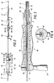
- FIG. 1 A fracture reduction tool 10 according to the present invention is shown in FIG. 1 in exploded form to illustrate the various components involved in its assembly. Also shown is a guide wire 12 which has an overall length greater than the length of the tool 10 when assembled.
- Guide wire 12 is of a typical straight construction and configuration and has a uniform diameter with an enlarged or beaded distal end 14 which is inserted into the medullary canal of the fractured bone such as a femur 15 as shown in FIG. 12.
- the guide wire 12 is inscribed at the distal portion with length marks 16 which typically are ten centimeters apart and at the proximal portion with an overall length marking 18.
- the tool 10 is formed of an elongated hollow shaft 20 which has a bore 22 shown more clearly in FIG. 11 for passage of guide wire 12. Accordingly bore 22 has a uniform diameter which is at least slightly larger than the diameter of guide wire 12 unrestricted passage therethrough.
- the distal end 24 of shaft 20 is beveled which aids in the penetration of the shaft 20 through the marrow within the medullary canal of the femur 15 as shown in FIG. 12.
- the distal portion 26 of shaft 20 also has inscribed thereon a plurality of length markings or graduations 27. Preferably these graduations 27 are shown in one centimeter increments.
- the range of these increments extends from about thirty centimeters to forty-eight centimeters which provides for use of this tool 10 with a variety of different sized bones and, in particular, the femur of the human body.
- the shaft 20 has a notch 28 as shown in FIG. 1 which is helpful in the assembly of tool 10 as explained more fully below.
- the fracture reducing tool 10 of the present invention is preferred for use in reducing fractures of the femur, it is contemplated that such tool 10 can also be used with other fractured bones with proper sizing of the shaft 20 so as to permit its entry and passage within the medullary canal of the respective fractured bone.
- the shaft 20 as shown in the preferred embodiments herein in the FIGS. is generally of a linear configuration, the shaft 20 can also be curved if desired in order to accommodate or correspond to the general curvature of the respective medullary canal involved.
- the tool 10 also includes a measurement member 30 which is a formed of tubular sleeve 32 having flange ends 34 and a body portion 36 with an oval window 38.
- the measurement sleeve 30 is sized in diameter so as to be capable of moving along and over the shaft 20 in the configuration as illustrated in FIG. 11.
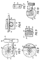
- Sleeve 30 also includes a thumb set screw 40 which has a screw rod 42 as shown in FIG. 10 that is sized for threaded passage through passageway 44 in body portion 36. Screw rod 42 thus can be threaded against the outer surface of shaft 20. In this fashion, the measurement sleeve 30 can be selectively locked into position at a predetermined location of shaft 20 to allow for ease of measurement.
- the thumb set screw 40 includes a knurled disc 46 attached to the free end of screw rod 42 to allow for easy rotation of the thumb set screw 40.
- the graduations 27 are viewable through window 38 as shown in FIG. 19.
- the body portion 36 has opposed arrow indicators 47 as shown in FIGS. 1 and 19 which are positioned midway of the window 38 so as to aid in determining or measuring the length of the nail or rod to be inserted into the medullary canal for fixation.
- the tool 10 as further shown in FIGS. 1 and 2, also includes a handle 48 which is formed of a cylindrical handle body 50 having an enlarged butt portion 51, handle grip 52 and handle rod 54.
- a cam rod 56 coupled to butt portion 51 allows for locking of the guide wire 12 selectively in position relative to the shaft 20 and handle 48.
- the handle body 50 has a bore 60 along its length and through which the guide wire 12 can freely pass.
- a collar 58 by means of threads within its bore at a proximal portion can be threaded onto corresponding threads positioned as shown in FIG. 3 on the distal end of handle body 50.
- the distal end of handle body 50 also includes an open end 62 into which the shaft 20 can be inserted for coupling with the handle 48.
- This open end 62 is configured to receive the notch 28 which is tightly fitted therein by means of wedge pin 63 as shown in FIGS. 1, 2 and 9.
- Wedge pin 63 is flush mounted in butt portion 51, i.e., it is shaved or ground off after insertion so as to be flush with the outer surface of butt portion 51.
- the handle rod 54 is secured onto handle body 50 by means of wedge pin 67.
- This pin 67 as shown in FIG. 3, is flush mounted with the outer surface of handle rod 54 and is preferably press-fitted through suitable holes in handle rod 54 and handle body 50.
- the open end 62 also includes a series of cut-away portions 64 which leave fingers 66 as shown in FIG. 1 which together with collar 58 function as a chuck for securing or locking the shaft 20 together with the handle 48.
- the cut-away portions 64 allow the fingers 66 to press into engaging contact with the outer surface of shaft 20 as shown in FIG. 3. In this fashion the collar 58 tightens down the fingers 66 so as to securely retain the shaft 20 within the open end 62 of handle 48.
- the bore 60 within the body handle 50 upon assembly is aligned coaxially with the bore 22 of shaft 20 as shown in FIG. 3. This permits guide wire 12 to be freely and selectively passed throughout the length of tool 10 until such time as it is locked in position by means of cam knob 56.
- the cam knob 56 includes a cam rod 68 which is positioned in a passageway in the butt portion 51 and extends therefrom to a free end.
- a four prong knob 70 is attached to the cam rod 68 free end.
- the cam rod 68 has a groove 72 which is suitably sized to receive a wedge pin 74 as shown in FIGS. 1, 2 and 7 which is flush mounted similar to wedge pin 63 and press-fitted through a hole in butt portion 51.
- the cam rod 68 also has a cam groove 76 whose outer surface acts as a cam as shown in FIG.
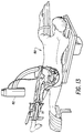
- the guide wire 12 with its beaded end 14 is assembled with tool 10 by insertion through bores 22 and 60 in the manner shown in FIG. 2. Thereafter, the tool 10 and guide wire 12 can be inserted through a suitably sized entry hole 78 shown in FIG. 16, and into the medullary canal of femur 15 as shown in FIG. 12. The tool 10 can then be positioned as desired within the medullary canal and the guide wire 12 extended through the canal portions so as to manipulate the various fragments of fractured femur 15. Once reduction is achieved, the guide wire 12 is fully inserted so that the beaded end 14 abuts the distal end of the medullary canal.
- the tool 10 can be positioned so that the proximal end of handle arm 54 is flush with the proximal end of guide wire 12.
- the measurement sleeve 30 is positioned so as to abut the greater trochanter of femur 15 as shown in FIG. 19.
- the arrow indicators 47 then provide a measurement of the pin or nail to be inserted into the medullary canal for fixation.
- the graduations 27 are calibrated to provide the nail or rod measurement when the tool 10 and guide wire 12 are positioned as described above.
- the tool 10 is preferably utilized with the guide wire 12 for reduction, alternatively the shaft 20 can be inserted as far into the medullary canal as desired so that reduction of the fragment portions can be achieved with shaft 20 itself.
- the supine position may also be used. Reduce the fracture in your usual manner. With this technique, anatomical reduction of the fracture prior to insertion of the reduction tool 10 is not necessary. However, the fracture must be reducible. Confirm this with the C-arm fluoroscope 82, positioned to permit good anteroposterior and lateral views from the hip to the knee.
- the proper entry site for the nail is very important and must be located directly over the medullary canal.
- the entry point is the fossa on the underside of the greater trochanter at its junction with the femoral neck in the midline of the anteroposterior plane.
- the fracture reduction tool 10 is used to: reduce the fracture, help pass the reaming guide wire and measure the length of nail to be used. Load the 3.0mm x 1000mm bead-tip guide wire 12 into the reduction tool 10 by passing it retrograde. Place the locking T-handle 88 on the proximal end of the wire 12.
- Reduction is usually easy, except in supracondylar fractures, where flexion of the distal fragment may require on additional anteriorly directed push on the proximal end of the distal fragment by an assistant.
- the reduction tool can be locked onto the wire 12 to drive it into the cancellous bone of the distal fragment. Verify proper position of the guide wire 12 with the fluoroscope 82 as shown in FIG. 17.
- the driving handle may be attached to control rotation as the nail or rod 92 is being driven.
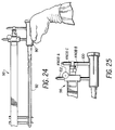
- the cross-locking drill guide 98 Prior to driving the rod 92, assemble the cross-locking drill guide 98 and set the cross-screw alignment. Mount the cross-locking drill guide 98 onto the driver assembly 90 as shown in FIG. 24. Note that the shorter 100 of the two mounting pins 100 and 102 is placed proximally. Slide the guide 98 over the mounting pins 100, 102. Estimate sufficient clearance to allow for the soft tissues of the thigh. Lock the guide 98 into place by hand-tightening Knob A as shown in FIG. 25. Place the two pilot pins in the distal guide holes on either side of the number representing the proper rod length.
- Unlock Knob B and adjust the guide 98 using the knurled adjustment wheel C until the pilot pins drop through the guide 98 into the center of the distal screw holes in the rod 92. During this procedure it is important to hold the rod 92 and cross-locking drill guide 98 only by the driving handle 90 as shown in FIGS. 24 and 25.
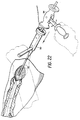
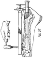
- Distal cross-locking is performed first, except when only proximal cross-locking is required. This maximizes accuracy for the distal screws. Locate the incision site by placing two alignment pins through the appropriate guide holes and marking the skin. Make a single longitudinal incision 104 and expose enough lateral cortex of the femur 15 so that soft tissue impingement on the drill sleeves 106 does not occur as shown in FIG. 26.
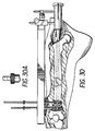
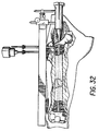
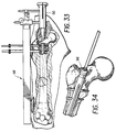
- the proximal targeting sequence is identical to distal targeting. Again, after placing the drills through the rod 92 and both cortices, the surgeon may check radiographically to make certain that they are through the holes in the rod 92 as in FIG. 32.
Landscapes
- Health & Medical Sciences (AREA)
- Surgery (AREA)
- Life Sciences & Earth Sciences (AREA)
- Orthopedic Medicine & Surgery (AREA)
- Engineering & Computer Science (AREA)
- Medical Informatics (AREA)
- Public Health (AREA)
- Veterinary Medicine (AREA)
- Biomedical Technology (AREA)
- Heart & Thoracic Surgery (AREA)
- Nuclear Medicine, Radiotherapy & Molecular Imaging (AREA)
- Molecular Biology (AREA)
- Animal Behavior & Ethology (AREA)
- General Health & Medical Sciences (AREA)
- Dentistry (AREA)
- Oral & Maxillofacial Surgery (AREA)
- Neurology (AREA)
- Mechanical Engineering (AREA)
- Surgical Instruments (AREA)
- Prostheses (AREA)
- Orthopedics, Nursing, And Contraception (AREA)
- Eye Examination Apparatus (AREA)
- Earth Drilling (AREA)
Claims (45)
- Ein Gerät zur Repositionierung eines gebrochenen Knochens, bestehend aus:a. Welle (20) mit einem fernen und einem nahen Ende, konfiguriert und dimensioniert für den Durchtritt und Eintritt ihres fernen Endes in den Markkanal des gebrochenen Knochens durch bzw. in eine geeignet bemessene Öffnung für Manipulationen in dem Markkanal durch Hin- und Herbewegungen sowie Drehbewegungen, um den gebrochenen Knochen durch Repositionierung der verschiedenen Knochenfragmente in ihrer richtigen relativen Anordnung zueinander einzurichten, wobei besagte Welle über einen Abschnitt mit Gradeinteilungen und entlang ihrer Länge mit einer Bohrung versehen ist; undb. Meßhülse (30), konfiguriert und dimensioniert für Bewegungen über mindestens den mit Gradeinteilungen versehenen Abschnitt von besagter Welle außerhalb des Markkanals, um die Länge eines in den Markkanal des eingerichteten Knochens zur Fixierung der Fraktur einzuführenden Nagels (92) bestimmen zu können.
- Das Gerät gemäß Anspruch 1, dadurch gekennzeichnet, daß besagte Welle eine lange Welle mit einem im allgemeinen gleichmäßigen Durchmesser über ihre gesamte Länge ist.
- Das Gerät gemäß Anspruch 2, dadurch gekennzeichnet, daß besagte Welle an ihrem fernen Ende abgefast ist.
- Das Gerät gemäß Anspruch 2, dadurch gekennzeichnet, daß besagte Welle entlang eines Abschnitts mit Gradeinteilungen versehen ist, die mit besagter Meßvorrichtung zur Bestimmung der Nagellänge zusammenarbeiten.
- Das Gerät gemäß Anspruch 4, dadurch gekennzeichnet, daß besagte Gradeinteilungen in gleichen Abständen voneinander entfernt sind.
- Das Gerät gemäß Anspruch 5, dadurch gekennzeichnet, daß sich besagte Gradeinteilungen im Bereich zwischen dreißig und achtundvierzig Zentimetern befinden.
- Das Gerät gemäß Anspruch 6, dadurch gekennzeichnet, daß besagte Gradeinteilungen in Abständen von jeweils einem Zentimeter angeordnet sind.
- Das Gerät gemäß Anspruch 4, dadurch gekennzeichnet, daß besagte Meßvorrichtung eine Rundhülse beinhaltet, die zumindest über den Abschnitt der besagten Welle verschiebbar ist, der mit den besagten Gradeinteilungen versehen ist.
- Das Gerät gemäß Anspruch 8, dadurch gekennzeichnet, daß besagte Rundhülse ein Fenster aufweist, das die Sicht auf besagte, unterhalb von diesem Fenster gelegene Gradeinteilungen auf der Welle freigibt.
- Das Gerät gemäß Anspruch 9, dadurch gekennzeichnet, daß besagte Rundhülse einen Hinweispfeil aufweist, der im allgemeinen genau in der Mitte des besagten Fensters angeordnet ist, so daß er die Vermessung der Länge des einzuführenden Nagels erleichtert.
- Das Gerät gemäß Anspruch 10, desweiteren umfassend eine Einrichtung zur selektiven Feststellung von besagter Meßvorrichtung an einer vorab bestimmten Position auf besagter Welle.
- Das Gerät gemäß Anspruch 11, dadurch gekennzeichnet, daß besagte Rundhülse desweiteren einen Durchgang aufweist, der eine Verbindung mit der Außenseite von besagter Welle herstellt, und daß besagte Meßvorrichtung eine Schraube beinhaltet, die für den kooperativen Eingriff mit besagtem Durchgang dimensioniert und konfiguriert ist, so daß besagte Schraube in besagten Durchgang bis zum Anschlag an besagte Außenseite eingeführt werden kann, um besagte Rundhülse selektiv auf der Welle festzustellen.
- Das Gerät gemäß Anspruch 2, desweiteren umfassend einen mit den, nahen Ende von besagter Welle gekoppelten Griff, der das Einführen und Bewegen von besagter Welle in den bzw. dem Markkanal erleichtert und der über seine Länge eine Bohrung aufweist, die koaxial mit der Bohrung von besagter Welle ausgerichtet ist.
- Das Gerät gemäß Anspruch 13, dadurch gekennzeichnet, daß besagter Griff einen langgestreckten Griffkörper aufweist, der an einem Ende geöffnet ist, um das nahe Ende von besagter Welle in sich aufnehmen zu können.
- Das Gerät gemäß Anspruch 14, desweiteren umfassend eine Spannvorrichtung zur selektiven Befestigung von besagter Welle an besagtem Griff.
- Das Gerät gemäß Anspruch 15, dadurch gekennzeichnet, daß besagte Spannvorrichtung ein ummittelbar neben dem besagten offenen Ende des Griffkörpers angeordnetes Gewinde sowie einen Bundring mit einer Bohrung aufweist, die so dimensioniert und konfiguriert ist, daß besagter Bundring zumindest entlang dem nahen Ende von besagter Welle bewegt werden kann, wobei besagter Bundring mit einem Innengewinde versehen ist, das dem Gewinde auf besagtem Griffkörper entspricht und so ein Ineinandergreifen besagter Gewinde gestattet, so daß besagter Griffkörper mit seinein offenen Ende durch den Bundring selektiv mit besagter Welle zusammengepreßt und so gesichert wird.
- Das Gerät gemäß Anspruch 16, dadurch gekennzeichnet, daß besagter Griff desweiteren einen im allgemeinen runden Griffteil umfaßt, der an einem Abschnitt von besagtem langgestreckten Griffkörper positioniert ist.
- Das Gerät gemäß Anspruch 17, dadurch gekennzeichnet, daß besagter Griff desweiteren eine Griffstange beinhaltet, die an dem fernen Ende von besagtem Griffkörper angeordnet ist und sich quer zu besagter Griffbohrung erstreckt.
- Ein Gerät zur Verwendung mit einem Führungsdraht zur Repositionierung eines gebrochenen Knochens, bestehend aus:a. Welle mit einem fernen Ende und einem nahen Ende, konfiguriert und dimensioniert für den Durchtritt und Eintritt ihres fernen Endes in den Markkanal des gebrochenen Knochens durch bzw. in eine geeignet bemessene Öffnung für Manipulationen in dem Markkanal durch Hin- und Herbewegungen sowie Drehbewegungen, um den gebrochenen Knochen durch Repositionierung der verschiedenen Knochenfragmente in ihrer richtigen relativen Anordnung zueinander einzurichten, wobei besagte Welle über einen Abschnitt mit Gradeinteilungen und über ihre Länge mit einer Bohrung versehen ist, die die selektive Durchführung des Führungsdrahtes gestattet; undb. Meßhülse, konfiguriert und dimensioniert für Bewegungen über mindestens den mit Gradeinteilungen versehen Wellenabschnitt außerhalb des Markkanals, um die Länge eines in den Markkanals des eingerichteten Knochens zur Fixierung der Fraktur einzuführenden Nagels bestimmen zu können.
- Das Gerät gemäß Anspruch 19, desweiteren umfassend einen mit dem nahen Ende von besagter Welle gekoppelten Griff, der das Einführen und Bewegen von besagter Welle in den bzw. dem Markkanal erleichtert und der über seine Länge eine Bohrung aufweist, die koaxial mit der Bohrung von besagter Welle verläuft, um die selektive Durchführung von besagtem Führungsdraht durch besagte Griffbohrung zu gestatten.
- Das Gerät gemäß Anspruch 20, desweiteren umfassend eine Vorrichtung zur selektiven Feststellung des Führungsdrahts innerhalb von besagter Griffbohrung in einer vorab festgelegten relativen Position zur Welle.
- Ein Gerät zur Verwendung mit einem Führungsdraht zur Repositionierung eines gebrochenen Oberschenkelknochens, wobei der Führungsdraht einen im allgemeinen gleichmäßigen Durchmesser aufweist und mit einem vergrößerten fernen Ende zur Plazierung in dem Markkanals des gebrochenen Oberschenkelknochens versehen ist, umfassend:a. Welle mit einem fernen und einem nahen Ende, konfiguriert und dimensioniert für den Durchtritt und Eintritt ihres fernen Endes in den Markkanal des gebrochenen Oberschenkelknochens durch bzw. in eine geeignet bemessene Öffnung für den Durchtritt von besagter Welle in den Markkanal und für Manipulationen von wenigstens der Welle oder des Führungsdrahts in den betreffenden Markkanalabschnitten des gebrochenen Oberschenkelknochens durch Hin- und Herbewegungen sowie Drehbewegungen, um den gebrochenen Oberschenkelknochen durch Repositionierung der verschiedenen Knochenfragmente in ihrer richtigen relativen Anordnung zueinander einzurichten, wobei besagte Welle über einen Abschnitt mit Gradeinteilungen und über ihre Länge mit einer Bohrung versehen ist, die die selektive Durchführung des Führungsdrahtes gestattet; undb. Meßhülse, die so konfiguriert und dimensioniert ist, daß sie sich zumindest über den mit Gradeinteilungen versehenen Abschnitt von besagter Welle außerhalb des Markkanals verschieben läßt, um die Länge eines in den Markkanal des eingerichteten Knochens zur Fixierung der Fraktur einzuführenden Nagels bestimmen zu können.
- Das Gerät gemäß Anspruch 22, dadurch gekennzeichnet, daß besagte Welle eine lange Hohlwelle mit einem im allgemeinen gleichmäßigen Durchmesser über ihre gesamte Länge ist.
- Das Gerät gemäß Anspruch 23, dadurch gekennzeichnet, daß besagte Welle am ihrem fernen Ende abgefast ist.
- Das Gerät gemäß Anspruch 24, dadurch gekennzeichnet, daß besagte Bohrung einen im allgemeinen gleichmäßigen Durchmesser über ihre gesamte Länge aufweist.
- Das Gerät gemäß Anspruch 25, dadurch gekennzeichnet, daß besagte Welle entlang eines Abschnitts mit Gradeinteilungen versehen ist. die mit besagter Meßvorrichtung zur Bestimmung der Nagellänge zusammenarbeiten.
- Das Gerät gemäß Anspruch 26, dadurch gekennzeichnet, daß besagte Gradeinteilungen in gleichen Abständen voneinander entfernt sind.
- Das Gerät gemäß Anspruch 27, dadurch gekennzeichnet, daß sich besagte Gradeinteilungen im Bereich zwischen dreißig und achtundvierzig Zentimetern befinden.
- Das Gerät gemäß Anspruch 28, dadurch gekennzeichnet, daß besagte Gradeinteilungen in Abständen von jeweils einem Zentimeter angeordnet sind.
- Das Gerät gemäß Anspruch 29, dadurch gekennzeichnet, daß besagte Meßvorrichtung eine Rundhülse beinhaltet, die zumindest über den Abschnitt der besagten Welle verschiebbar ist, der mit den besagten Gradeinteilungen versehen ist.
- Das Gerät gemäß Anspruch 30, dadurch gekennzeichnet, daß besagte Rundhülse ein Fenster aufweist, das Sicht auf besagte, unterhalb von besagtem Fenster gelegene Gradeinteilungen auf der Welle freigibt.
- Das Gerät gemäß Anspruch 31, dadurch gekennzeichnet, daß besagte Rundhülse einen Hinweispfeil aufweist, der im allgemeinen genau in der Mitte des besagten Fensters angeordnet ist, so daß er die Vermessung der Länge des einzuführenden Nagels erleichtert.
- Das Gerät gemäß Anspruch 32, desweiteren umfassend eine Einrichtung zur selektiven Feststellung von besagter Meßvorrichtung an einer vorab bestimmten Position auf besagter Welle.
- Das Gerät gemäß Anspruch 33, dadurch gekennzeichnet, daß besagte Rundhülse desweiteren einen Durchgang aufweist, der eine Verbindung mit der Außenseite von besagter Welle herstellt, und daß besagte Meßvorrichtung eine Schraube umfaßt, die zum kooperativen Eingriff mit besagtem Durchgang dimensioniert und konfiguriert ist, so daß besagte Schraube in besagten Durchgang bis zum Anschlag an besagte Außenseite eingeführt werden kann, um besagte Rundhülse selektiv auf der Welle fest zustellen.
- Das Gerät gemäß Anspruch 34, desweiteren umfassend einen mit dem nahen Ende von besagter Welle gekoppelten Griff, der das Einführen und Bewegen von besagter Welle in den bzw. dem Markkanal erleichtert und der über seine Länge eine Bohrung aufweist, die koaxial mit der Bohrung von besagter Welle ausgerichtet ist, um die selektive Durchführung des Führungsdrahts durch besagte Griffbohrung zu gestatten.
- Das Gerät gemäß Anspruch 35, dadurch gekennzeichnet, daß besagter Griff einen langgestreckten Griffkörper aufweist, der an einem Ende geöffnet ist, um das nahe Ende von besagter Welle in sich aufnehmen zu können.
- Das Gerät gemäß Anspruch 36, desweiteren umfassend eine Spannvorrichtung zur selektiven Befestigung von besagter Welle an besagtem Griff.
- Das Gerät gemäß Anspruch 37, dadurch gekennzeichnet, daß besagte Spannvorrichtung ein unmittelbar neben dem besagten offenen Ende des Griffkörpers angeordnetes Gewinde sowie einen Bundring mit einer Bohrung aufweist, die so dimensioniert und konfiguriert ist, daß besagter Bundring zumindest entlang dem nahen Ende von besagter Welle bewegt werden kann, wobei besagter Bundring mit einem Innengewinde versehen ist, das dem Gewinde auf besagtem Griffkörper entspricht und so ein Ineinandergreifen besagter Gewinde gestattet, so daß besagter Griffkörper mit seinen) offenen Ende durch den Bundring selektiv mit besagter Welle zusammengepreßt und so gesichert wird.
- Das Gerät gemäß Anspruch 38, dadurch gekennzeichnet, daß besagter Griff desweiteren einen im allgemeinen runden Griffteil umfaßt, der an einem Abschnitt von besagtem langgestreckten Griffkörper angeordnet ist.
- Das Gerät gemäß Anspruch 39, dadurch gekennzeichnet, daß besagter Griff desweiteren eine Griffstange beinhaltet, die an dem fernen Ende von besagtem Griffkörper angeordnet ist und sich quer zu besagter Griffbohrung erstreckt.
- Das Gerät gemäß Anspruch 40, dadurch gekennzeichnet, daß besagter Griffteil in besagten Abschnitt des langgestreckten Griffkörpers fest eingearbeitet ist.
- Das Gerät gemäß Anspruch 36, desweiteren umfassend eine Einrichtung zur selektiven Feststellung des Führungsdrahtes innerhalb der Griffbohrung in einer vorab bestimmten Position relativ zu besagter Welle.
- Das Gerät gemäß Anspruch 41, dadurch gekennzeichnet, daß besagter Griffteil einen Durchgang aufweist, der eine Verbindung mit besagter Griffbohrung herstellt und der sich quer zu besagter Griffbohrung erstreckt.
- Das Gerät gemäß Anspruch 43, dadurch gekennzeichnet, daß besagte Führungsdraht-Feststelleinrichtung eine Stange beinhaltet, die so dimensioniert ist, daß sie in besagtem Griffkörper-Durchgang so positioniert werden kann, daß ein freies Ende übersteht, wobei besagte Stange einen Nocken aufweist, der so auf ihr angeordnet ist, daß er in besagte Griffbohrung während zumindest eines Teils einer vollständigen Drehung von besagter Stange hineinragt, wobei besagter Nocken so konfiguriert und dimensioniert ist, daß er beim Eingreifen in besagte Bohrung den Führungsdraht berührt und diesen selektiv in einer Position relativ zu besagter Welle feststellt.
- Das Gerät gemäß Anspruch 44, desweiteren umfassend einen Knopf, der an besagtem freien Ende von besagter Nockenstange befestigt ist und der dazu dient, das Drehen von besagter Nockenstange bequemer zu gestalten.
Applications Claiming Priority (3)
| Application Number | Priority Date | Filing Date | Title |
|---|---|---|---|
| US152172 | 1988-02-04 | ||
| US07/152,172 US5122146A (en) | 1988-02-04 | 1988-02-04 | Apparatus for reducing a fracture |
| PCT/US1989/000436 WO1989006948A1 (en) | 1988-02-04 | 1989-02-03 | Apparatus for reducing a fracture |
Publications (3)
| Publication Number | Publication Date |
|---|---|
| EP0400062A1 EP0400062A1 (de) | 1990-12-05 |
| EP0400062A4 EP0400062A4 (en) | 1991-03-20 |
| EP0400062B1 true EP0400062B1 (de) | 1995-05-17 |
Family
ID=22541788
Family Applications (1)
| Application Number | Title | Priority Date | Filing Date |
|---|---|---|---|
| EP89902870A Expired - Lifetime EP0400062B1 (de) | 1988-02-04 | 1989-02-03 | Vorrichtung zur reduzierung eines bruches |
Country Status (8)
| Country | Link |
|---|---|
| US (1) | US5122146A (de) |
| EP (1) | EP0400062B1 (de) |
| JP (1) | JP2753357B2 (de) |
| AT (1) | ATE122552T1 (de) |
| CA (1) | CA1321520C (de) |
| DE (1) | DE68922722D1 (de) |
| ES (1) | ES2012977A6 (de) |
| WO (1) | WO1989006948A1 (de) |
Families Citing this family (95)
| Publication number | Priority date | Publication date | Assignee | Title |
|---|---|---|---|---|
| US5100404A (en) * | 1990-09-04 | 1992-03-31 | Beth Israel Hospital | Intramedullary nailing method and apparatus |
| IT1253255B (it) * | 1991-08-02 | 1995-07-14 | Orthofix Srl | Strumentario chirurgico per l'impianto,il fissaggio in opera e l'estrazione di chiodi intermidollari |
| US5681318A (en) * | 1992-02-13 | 1997-10-28 | Orthofix S.R.L. | Medullary cavity template |
| US5342366A (en) * | 1992-02-19 | 1994-08-30 | Biomet, Inc. | Surgical instruments for hip revision |
| FR2689751B1 (fr) * | 1992-04-08 | 1998-02-06 | Medinov Sa | Appareil pour la pose d'un clou centro medullaire. |
| EP0589592A3 (de) * | 1992-09-22 | 1994-10-19 | Orthofix Srl | Zentrierungsmittel für Löcher von Marknägeln. |
| US5599290A (en) | 1992-11-20 | 1997-02-04 | Beth Israel Hospital | Bone fracture prevention garment and method |
| US5429640A (en) * | 1992-11-27 | 1995-07-04 | Clemson University | Intramedullary rod for fracture fixation of femoral shaft independent of ipsilateral femoral neck fracture fixation |
| US5702401A (en) * | 1993-06-23 | 1997-12-30 | Shaffer; Benjamin | Intra-articular measuring device |
| US5509919A (en) * | 1993-09-24 | 1996-04-23 | Young; Merry A. | Apparatus for guiding a reaming instrument |
| US5989260A (en) * | 1994-08-22 | 1999-11-23 | Yao; Meei-Huei | Intramedullary nail guide rod with measure scale marked thereon |
| US5695496A (en) * | 1995-01-17 | 1997-12-09 | Smith & Nephew Inc. | Method of measuring bone strain to detect fracture consolidation |
| US5766180A (en) * | 1995-07-31 | 1998-06-16 | Winquist; Robert A. | Nail extraction kit and method |
| US5645545A (en) * | 1995-08-14 | 1997-07-08 | Zimmer, Inc. | Self reaming intramedullary nail and method for using the same |
| US5690842A (en) * | 1995-09-12 | 1997-11-25 | Zimmer, Inc. | Orthopaedic wire with an enlarged end and method of forming the same |
| US5942261A (en) * | 1996-07-05 | 1999-08-24 | Dreith; Karen M. | Handheld modeling tool |
| US6093468A (en) * | 1997-03-14 | 2000-07-25 | The Procter & Gamble Company | Flexible lightweight protective pad with energy absorbing inserts |
| US5895389A (en) * | 1997-05-29 | 1999-04-20 | Synthes (U.S.A.) | Drilling guide and measuring instrumentation |
| US6200323B1 (en) * | 1998-12-04 | 2001-03-13 | Pierson, Iii Raymond H. | Bone depth resection guide and method |
| US6527775B1 (en) * | 2000-09-22 | 2003-03-04 | Piper Medical, Inc. | Intramedullary interlocking fixation device for the distal radius |
| US6524259B2 (en) * | 2001-06-08 | 2003-02-25 | Cervilenz, Inc. | Devices and methods for cervix measurement |
| WO2003030749A1 (es) * | 2001-10-12 | 2003-04-17 | Flores Davila Jorge P | Clavo centro medular ranurado y metodo para la osteosintesis de segmentos diafisiarios |
| US7175632B2 (en) * | 2002-05-15 | 2007-02-13 | Linvatec Corporation | Cross-pin graft fixation instruments and method |
| US8652142B2 (en) * | 2006-04-28 | 2014-02-18 | Acumed Llc | Osteotomy systems |
| US20060036232A1 (en) | 2002-10-04 | 2006-02-16 | Tyco Healthcare Group Lp | Surgical suturing apparatus with measurement structure |
| DE20216857U1 (de) * | 2002-11-02 | 2003-02-20 | stryker Trauma GmbH, 24232 Schönkirchen | Zielgerät für einen Verriegelungsnagel |
| KR100521388B1 (ko) * | 2002-11-14 | 2005-10-12 | 조태준 | 골형성 부전증 치료장치 |
| US7559931B2 (en) | 2003-06-09 | 2009-07-14 | OrthAlign, Inc. | Surgical orientation system and method |
| US7299561B2 (en) * | 2003-10-15 | 2007-11-27 | Depuy Products, Inc. | Gauge system for use in implantation of a fracture fixation device |
| US7901411B2 (en) * | 2004-02-10 | 2011-03-08 | Smith & Nephew, Inc. | Hip replacement incision locator |
| US8070750B2 (en) | 2004-03-05 | 2011-12-06 | Depuy Mitek, Inc. | Tunnel notcher and guidewire delivery device |
| US7488327B2 (en) | 2004-04-12 | 2009-02-10 | Synthes (U.S.A.) | Free hand drill guide |
| US20050240197A1 (en) * | 2004-04-23 | 2005-10-27 | Kmiec Stanley J Jr | Device and method for inserting, positioning and removing an implant |
| US20060015101A1 (en) | 2004-07-15 | 2006-01-19 | Wright Medical Technology, Inc. | Intramedullary fixation assembly and devices and methods for installing the same |
| US7588577B2 (en) * | 2004-07-15 | 2009-09-15 | Wright Medical Technology, Inc. | Guide assembly for intramedullary fixation and method of using the same |
| US7749223B2 (en) * | 2004-08-09 | 2010-07-06 | Howmedica Osteonics Corp. | Navigated femoral axis finder |
| USD537940S1 (en) | 2004-08-11 | 2007-03-06 | Synthes (Usa) | Head for surgical hammer |
| AU2006200152B2 (en) * | 2005-01-14 | 2012-06-07 | Smith & Nephew, Inc. | Hip replacement incision locator |
| US7491203B2 (en) * | 2005-02-14 | 2009-02-17 | Wright Medical Technology, Inc. | Instruments for bone screws |
| US9060820B2 (en) | 2005-05-18 | 2015-06-23 | Sonoma Orthopedic Products, Inc. | Segmented intramedullary fracture fixation devices and methods |
| US7846162B2 (en) | 2005-05-18 | 2010-12-07 | Sonoma Orthopedic Products, Inc. | Minimally invasive actuable bone fixation devices |
| US8961516B2 (en) | 2005-05-18 | 2015-02-24 | Sonoma Orthopedic Products, Inc. | Straight intramedullary fracture fixation devices and methods |
| DE602006020757D1 (de) | 2005-11-04 | 2011-04-28 | Bosch Gmbh Robert | Drehmomentbegrenzungsfeedbacks in einem schlagbohrer |
| US7885705B2 (en) * | 2006-02-10 | 2011-02-08 | Murphy Stephen B | System and method for facilitating hip surgery |
| CN101384401A (zh) * | 2006-02-16 | 2009-03-11 | 彼多·约瑟·祖比亚里·阿尔伯蒂 | 手用器具或用具的手柄连接器 |
| US8685034B2 (en) * | 2006-08-10 | 2014-04-01 | Stryker Trauma Gmbh | Distal targeting device |
| CA2670263A1 (en) | 2006-11-22 | 2008-05-29 | Sonoma Orthopedic Products, Inc. | Fracture fixation device, tools and methods |
| US8961522B2 (en) * | 2007-01-25 | 2015-02-24 | Biomet C.V. | Flexible shaft reduction tool |
| US20090112215A1 (en) * | 2007-10-29 | 2009-04-30 | Sherman Jason T | Opto-electric indicators for orthopaedic instruments |
| US8771283B2 (en) | 2007-12-17 | 2014-07-08 | Wright Medical Technology, Inc. | Guide assembly for intramedullary fixation and method of using the same |
| WO2009099963A2 (en) * | 2008-01-31 | 2009-08-13 | Cayenne Medical, Inc | Self-tapping biocompatible interference bone screw |
| US8496665B2 (en) * | 2008-02-13 | 2013-07-30 | Biomet C.V. | Drill sleeve |
| EP2299917A1 (de) | 2008-06-10 | 2011-03-30 | Sonoma Orthopedic Products, Inc. | Frakturfixationsvorrichtung, werkzeuge und verfahren |
| US20100064216A1 (en) | 2008-07-24 | 2010-03-11 | OrthAlign, Inc. | Systems and methods for joint replacement |
| WO2010030809A1 (en) | 2008-09-10 | 2010-03-18 | Orthalign, Inc | Hip surgery systems and methods |
| AU2009296243A1 (en) | 2008-09-26 | 2010-04-01 | Sonoma Orthopedic Products, Inc. | Bone fixation device, tools and methods |
| US20110015634A1 (en) * | 2009-07-14 | 2011-01-20 | Biomet Manufacturing Corp. | Modular Reaming System for Femoral Revision |
| US10869771B2 (en) | 2009-07-24 | 2020-12-22 | OrthAlign, Inc. | Systems and methods for joint replacement |
| US8118815B2 (en) | 2009-07-24 | 2012-02-21 | OrthAlign, Inc. | Systems and methods for joint replacement |
| CA2778838A1 (en) | 2009-11-12 | 2011-05-19 | Cervilenz Inc. | Devices and methods for cervix measurement |
| WO2011067668A1 (en) * | 2009-12-01 | 2011-06-09 | Dalhousie University | Steerable femoral fracture reduction device |
| AU2011341678B2 (en) | 2010-01-21 | 2014-12-11 | OrthAlign, Inc. | Systems and methods for joint replacement |
| US8221432B2 (en) | 2010-03-05 | 2012-07-17 | Biomet Manufacturing Corp. | Method and apparatus for implanting a modular femoral hip |
| US8529569B2 (en) | 2010-03-05 | 2013-09-10 | Biomet Manufacturing, Llc | Method and apparatus for preparing a proximal femur |
| US8460393B2 (en) * | 2010-03-05 | 2013-06-11 | Biomet Manufacturing Corp. | Modular lateral hip augments |
| US8679130B2 (en) * | 2010-03-05 | 2014-03-25 | Biomet Manufacturing, Llc | Guide assembly for lateral implants and associated methods |
| US8419743B2 (en) | 2010-03-05 | 2013-04-16 | Biomet Manufacturing Corp. | Assembly tool for modular implants and associated method |
| US8333807B2 (en) * | 2010-03-05 | 2012-12-18 | Biomet Manufacturing Corp. | Method and apparatus for trialing and implanting a modular femoral hip |
| AU2011227190B2 (en) * | 2010-03-18 | 2016-04-14 | Smith & Nephew, Inc. | A device for use during ligament reconstruction surgery |
| AU2013262624B2 (en) | 2012-05-18 | 2018-03-01 | OrthAlign, Inc. | Devices and methods for knee arthroplasty |
| US9572589B2 (en) | 2012-07-10 | 2017-02-21 | Stryker European Holdings I, Llc | Drill guide |
| US9649160B2 (en) | 2012-08-14 | 2017-05-16 | OrthAlign, Inc. | Hip replacement navigation system and method |
| DE202012103384U1 (de) | 2012-09-05 | 2012-09-24 | Signus Medizintechnik Gmbh | Beckenringimplantat |
| CN103110463A (zh) * | 2013-03-01 | 2013-05-22 | 华北石油管理局总医院 | 股骨粗隆顶点开髓导向器 |
| US9386997B2 (en) | 2013-03-29 | 2016-07-12 | Smith & Nephew, Inc. | Tunnel gage |
| WO2014194965A1 (en) | 2013-06-07 | 2014-12-11 | Stryker Trauma Gmbh | Targeting adjustment system for an intramedullary nail |
| US9770278B2 (en) | 2014-01-17 | 2017-09-26 | Arthrex, Inc. | Dual tip guide wire |
| US9814499B2 (en) | 2014-09-30 | 2017-11-14 | Arthrex, Inc. | Intramedullary fracture fixation devices and methods |
| US10098646B2 (en) | 2014-09-30 | 2018-10-16 | Medos International Sàrl | Surgical guide for use in ligament repair procedures |
| US10045789B2 (en) | 2014-09-30 | 2018-08-14 | Medos International Sàrl | Universal surgical guide systems and methods |
| US10307173B2 (en) | 2014-09-30 | 2019-06-04 | Medos International Sàrl | Gage for limiting distal travel of drill pin |
| US10010333B2 (en) | 2014-09-30 | 2018-07-03 | Medos International Sàrl | Side-loading carriage for use in surgical guide |
| US10363149B2 (en) | 2015-02-20 | 2019-07-30 | OrthAlign, Inc. | Hip replacement navigation system and method |
| CN204797977U (zh) * | 2015-06-30 | 2015-11-25 | 深圳雅涵医疗美容门诊部 | 下颌角截骨定位装置 |
| WO2017113005A1 (en) * | 2015-12-30 | 2017-07-06 | Rolof Rick L | Brake impact tool |
| JP7344122B2 (ja) | 2017-03-14 | 2023-09-13 | オースアライン・インコーポレイテッド | 軟部組織の測定およびバランシングを行うシステムおよび方法 |
| EP3595554A4 (de) | 2017-03-14 | 2021-01-06 | OrthAlign, Inc. | Hüftersatznavigationssystem und -verfahren |
| WO2018237276A1 (en) * | 2017-06-23 | 2018-12-27 | Orthopediatrics Corp. | Insertion apparatus for an intramedullary nail |
| MX2020003481A (es) | 2017-10-11 | 2020-12-07 | Howmedica Osteonics Corp | Guias para placa de fijacion de la cabeza humeral. |
| USD894385S1 (en) | 2017-10-27 | 2020-08-25 | Orthopediatrics Corp. | Orthopedic tool |
| CN110141338B (zh) * | 2019-06-14 | 2025-02-11 | 陈聚伍 | 骨折快速复位装置 |
| WO2022051167A1 (en) * | 2020-09-03 | 2022-03-10 | Acumed Llc | Drill having radiographically visible depth indications |
| WO2022072228A1 (en) * | 2020-10-02 | 2022-04-07 | Acumed Llc | Cannulated screw length measurement gauge |
| US12011199B2 (en) | 2020-10-15 | 2024-06-18 | DePuy Synthes Products, Inc. | Bone plate, bone plate system, and method of using the same |
| US11806029B2 (en) | 2021-01-06 | 2023-11-07 | DePuy Synthes Products, Inc. | Locking trocar and method of using the same |
Family Cites Families (11)
| Publication number | Priority date | Publication date | Assignee | Title |
|---|---|---|---|---|
| US2235419A (en) * | 1938-03-18 | 1941-03-18 | James J Callahan | Fracture nail and director |
| US2650435A (en) * | 1950-07-10 | 1953-09-01 | Lloyd L Kidd | Multipurpose depth gauge |
| US2716406A (en) * | 1953-09-16 | 1955-08-30 | Austenal Lab Inc | Hip-nail driver for angular hip nails |
| GB1161312A (en) * | 1965-09-17 | 1969-08-13 | Nat Res Dev | Fixation Implants for use in Hip Surgery |
| US4121572A (en) * | 1977-02-07 | 1978-10-24 | G.D. Searle & Co. | Uterine sound |
| US4103683A (en) * | 1977-06-03 | 1978-08-01 | Neufeld John A | Sub-trochanteric nail |
| US4341206A (en) * | 1978-12-19 | 1982-07-27 | Synthes Ag | Device for producing a hole in a bone |
| US4465065A (en) * | 1983-01-07 | 1984-08-14 | Yechiel Gotfried | Surgical device for connection of fractured bones |
| SE442083B (sv) * | 1984-03-14 | 1985-12-02 | Magnus Odensten | Anordning for inriktning och styrning av en fram och ater forskjutbar borrstang for borrning av ett genomgaende hal i atminstone den ena av tva en kneled bildande sken- och larben |
| EP0187283B1 (de) * | 1984-12-26 | 1989-04-26 | Nivarox-FAR S.A. | Vorrichtung zum Auffinden in situ der Querbohrungen eines im Markkanal implantierten hohlen Stiftes für das Zusammenhalten der Fragmente eines gebrochenen Knochens |
| US4800873A (en) * | 1987-08-31 | 1989-01-31 | Audell Robert A | Method for setting fractures |
-
1988
- 1988-02-04 US US07/152,172 patent/US5122146A/en not_active Expired - Lifetime
-
1989
- 1989-02-02 CA CA000589926A patent/CA1321520C/en not_active Expired - Lifetime
- 1989-02-03 WO PCT/US1989/000436 patent/WO1989006948A1/en not_active Ceased
- 1989-02-03 DE DE68922722T patent/DE68922722D1/de not_active Expired - Lifetime
- 1989-02-03 AT AT89902870T patent/ATE122552T1/de not_active IP Right Cessation
- 1989-02-03 EP EP89902870A patent/EP0400062B1/de not_active Expired - Lifetime
- 1989-02-03 ES ES8900382A patent/ES2012977A6/es not_active Expired - Fee Related
- 1989-02-03 JP JP1502662A patent/JP2753357B2/ja not_active Expired - Lifetime
Also Published As
| Publication number | Publication date |
|---|---|
| ES2012977A6 (es) | 1990-04-16 |
| EP0400062A1 (de) | 1990-12-05 |
| CA1321520C (en) | 1993-08-24 |
| DE68922722D1 (de) | 1995-06-22 |
| WO1989006948A1 (en) | 1989-08-10 |
| ATE122552T1 (de) | 1995-06-15 |
| JP2753357B2 (ja) | 1998-05-20 |
| EP0400062A4 (en) | 1991-03-20 |
| JPH03503493A (ja) | 1991-08-08 |
| US5122146A (en) | 1992-06-16 |
Similar Documents
| Publication | Publication Date | Title |
|---|---|---|
| US5122146A (en) | Apparatus for reducing a fracture | |
| US7175631B2 (en) | Radiolucent aiming guide | |
| US4383527A (en) | Device for guiding the insertion of surgical wires into bone tissue | |
| US4913137A (en) | Intramedullary rod system | |
| EP1350479B1 (de) | Befestigungselement und Zielvorrichtung für einen intramedullären Marknagel | |
| US5403322A (en) | Drill guide and method for avoiding intramedullary nails in the placement of bone pins | |
| US4450835A (en) | Method and system for inserting a surgical wire | |
| US4978351A (en) | Guiding instrument to pierce the bone cortical, auxiliary in the location of the holes for intra-marrow pins | |
| US6852115B2 (en) | Multi-functional orthopedic surgical instrument and method of using same | |
| US5207753A (en) | Bone fracture repair apparatus and method | |
| EP1948040B1 (de) | Zielvorrichtung | |
| EP1755468B1 (de) | Implantatanordnung | |
| US7753914B2 (en) | Orthopaedic gage, kit and associated method | |
| EP1723917B1 (de) | Vorrichtung zum Einsetzen eines Knochenbefestigungsmittels | |
| HU219014B (hu) | Fúrókészülék velőűrszegek rögzítésére | |
| HK167596A (en) | Surgery device to position osteosynthesis fixation elements, particularly bone screws | |
| JPH10501438A (ja) | 骨髄内釘 | |
| KR101313172B1 (ko) | 정형외과용 임플란트 삽입 핸들 및 조준 가이드 | |
| JPH07178116A (ja) | 脊椎を経皮的に固定する方法及びその方法に使用されるキット並びに椎根ねじ | |
| MacMillan et al. | A simplified technique of distal femoral screw insertion for the Grosse-Kempf interlocking nail | |
| US7060070B1 (en) | Locking nail and aim-taking apparatus | |
| GB2159680A (en) | Surgical targetting device | |
| JP3342999B2 (ja) | 髄内釘のラグスクリュー挿入方向確定装置 | |
| CA1177351A (en) | Surgical guide pin-external sleeve combination | |
| Séquin et al. | Instruments for the Screw and Plate Fixation of Large Bones |
Legal Events
| Date | Code | Title | Description |
|---|---|---|---|
| PUAI | Public reference made under article 153(3) epc to a published international application that has entered the european phase |
Free format text: ORIGINAL CODE: 0009012 |
|
| 17P | Request for examination filed |
Effective date: 19900801 |
|
| AK | Designated contracting states |
Kind code of ref document: A1 Designated state(s): AT BE CH DE FR GB IT LI LU NL SE |
|
| A4 | Supplementary search report drawn up and despatched |
Effective date: 19910131 |
|
| AK | Designated contracting states |
Kind code of ref document: A4 Designated state(s): AT BE CH DE FR GB IT LI LU NL SE |
|
| 17Q | First examination report despatched |
Effective date: 19920716 |
|
| RAP1 | Party data changed (applicant data changed or rights of an application transferred) |
Owner name: HOWMEDICA INC. |
|
| GRAA | (expected) grant |
Free format text: ORIGINAL CODE: 0009210 |
|
| AK | Designated contracting states |
Kind code of ref document: B1 Designated state(s): AT BE CH DE FR GB IT LI LU NL SE |
|
| PG25 | Lapsed in a contracting state [announced via postgrant information from national office to epo] |
Ref country code: FR Effective date: 19950517 Ref country code: AT Effective date: 19950517 Ref country code: IT Free format text: LAPSE BECAUSE OF FAILURE TO SUBMIT A TRANSLATION OF THE DESCRIPTION OR TO PAY THE FEE WITHIN THE PRESCRIBED TIME-LIMIT;WARNING: LAPSES OF ITALIAN PATENTS WITH EFFECTIVE DATE BEFORE 2007 MAY HAVE OCCURRED AT ANY TIME BEFORE 2007. THE CORRECT EFFECTIVE DATE MAY BE DIFFERENT FROM THE ONE RECORDED. Effective date: 19950517 Ref country code: NL Free format text: LAPSE BECAUSE OF FAILURE TO SUBMIT A TRANSLATION OF THE DESCRIPTION OR TO PAY THE FEE WITHIN THE PRESCRIBED TIME-LIMIT Effective date: 19950517 Ref country code: BE Effective date: 19950517 |
|
| REF | Corresponds to: |
Ref document number: 122552 Country of ref document: AT Date of ref document: 19950615 Kind code of ref document: T |
|
| REF | Corresponds to: |
Ref document number: 68922722 Country of ref document: DE Date of ref document: 19950622 |
|
| PG25 | Lapsed in a contracting state [announced via postgrant information from national office to epo] |
Ref country code: SE Effective date: 19950817 |
|
| PG25 | Lapsed in a contracting state [announced via postgrant information from national office to epo] |
Ref country code: DE Effective date: 19950818 |
|
| EN | Fr: translation not filed | ||
| NLV1 | Nl: lapsed or annulled due to failure to fulfill the requirements of art. 29p and 29m of the patents act | ||
| PG25 | Lapsed in a contracting state [announced via postgrant information from national office to epo] |
Ref country code: GB Effective date: 19960203 |
|
| PG25 | Lapsed in a contracting state [announced via postgrant information from national office to epo] |
Ref country code: LI Free format text: LAPSE BECAUSE OF NON-PAYMENT OF DUE FEES Effective date: 19960228 Ref country code: CH Free format text: LAPSE BECAUSE OF NON-PAYMENT OF DUE FEES Effective date: 19960228 |
|
| PG25 | Lapsed in a contracting state [announced via postgrant information from national office to epo] |
Ref country code: LU Free format text: LAPSE BECAUSE OF NON-PAYMENT OF DUE FEES Effective date: 19960229 |
|
| PLBE | No opposition filed within time limit |
Free format text: ORIGINAL CODE: 0009261 |
|
| STAA | Information on the status of an ep patent application or granted ep patent |
Free format text: STATUS: NO OPPOSITION FILED WITHIN TIME LIMIT |
|
| 26N | No opposition filed | ||
| GBPC | Gb: european patent ceased through non-payment of renewal fee |
Effective date: 19960203 |
|
| REG | Reference to a national code |
Ref country code: CH Ref legal event code: PL |