EP0400074B1 - Geschützter drucksensor - Google Patents
Geschützter drucksensor Download PDFInfo
- Publication number
- EP0400074B1 EP0400074B1 EP89903349A EP89903349A EP0400074B1 EP 0400074 B1 EP0400074 B1 EP 0400074B1 EP 89903349 A EP89903349 A EP 89903349A EP 89903349 A EP89903349 A EP 89903349A EP 0400074 B1 EP0400074 B1 EP 0400074B1
- Authority
- EP
- European Patent Office
- Prior art keywords
- diaphragm
- sensor
- recess
- pressure
- cavity
- Prior art date
- Legal status (The legal status is an assumption and is not a legal conclusion. Google has not performed a legal analysis and makes no representation as to the accuracy of the status listed.)
- Expired - Lifetime
Links
- 239000000463 material Substances 0.000 claims abstract description 90
- 238000012546 transfer Methods 0.000 claims abstract description 44
- 238000000034 method Methods 0.000 claims abstract description 43
- 239000007787 solid Substances 0.000 claims abstract description 17
- 125000000118 dimethyl group Chemical group [H]C([H])([H])* 0.000 claims abstract description 9
- 229920001296 polysiloxane Polymers 0.000 claims abstract description 7
- 230000037361 pathway Effects 0.000 claims description 4
- 230000009969 flowable effect Effects 0.000 claims description 2
- 238000007789 sealing Methods 0.000 claims description 2
- 238000012360 testing method Methods 0.000 claims description 2
- 230000004888 barrier function Effects 0.000 claims 2
- 239000002210 silicon-based material Substances 0.000 claims 2
- 229920001971 elastomer Polymers 0.000 claims 1
- 229920002529 medical grade silicone Polymers 0.000 claims 1
- 239000012528 membrane Substances 0.000 abstract description 33
- 230000008569 process Effects 0.000 abstract description 14
- 238000004519 manufacturing process Methods 0.000 abstract description 11
- 230000015572 biosynthetic process Effects 0.000 abstract 1
- 238000011065 in-situ storage Methods 0.000 abstract 1
- 239000004065 semiconductor Substances 0.000 description 16
- 239000000499 gel Substances 0.000 description 9
- 239000007788 liquid Substances 0.000 description 8
- 230000035945 sensitivity Effects 0.000 description 8
- GWEVSGVZZGPLCZ-UHFFFAOYSA-N Titan oxide Chemical compound O=[Ti]=O GWEVSGVZZGPLCZ-UHFFFAOYSA-N 0.000 description 4
- 230000002411 adverse Effects 0.000 description 4
- 230000008878 coupling Effects 0.000 description 4
- 238000010168 coupling process Methods 0.000 description 4
- 238000005859 coupling reaction Methods 0.000 description 4
- 239000000853 adhesive Substances 0.000 description 3
- 230000001070 adhesive effect Effects 0.000 description 3
- 230000008901 benefit Effects 0.000 description 3
- 229910052751 metal Inorganic materials 0.000 description 3
- 239000002184 metal Substances 0.000 description 3
- 238000013459 approach Methods 0.000 description 2
- 230000002238 attenuated effect Effects 0.000 description 2
- 238000011109 contamination Methods 0.000 description 2
- -1 for example Polymers 0.000 description 2
- 239000004033 plastic Substances 0.000 description 2
- 238000005096 rolling process Methods 0.000 description 2
- 239000004408 titanium dioxide Substances 0.000 description 2
- 239000004727 Noryl Substances 0.000 description 1
- 229920001207 Noryl Polymers 0.000 description 1
- 229920000265 Polyparaphenylene Polymers 0.000 description 1
- 239000004734 Polyphenylene sulfide Substances 0.000 description 1
- 229920013632 Ryton Polymers 0.000 description 1
- 239000004736 Ryton® Substances 0.000 description 1
- 230000000712 assembly Effects 0.000 description 1
- 238000000429 assembly Methods 0.000 description 1
- 230000009286 beneficial effect Effects 0.000 description 1
- 210000001124 body fluid Anatomy 0.000 description 1
- 238000004891 communication Methods 0.000 description 1
- 239000004020 conductor Substances 0.000 description 1
- 230000001419 dependent effect Effects 0.000 description 1
- 238000013461 design Methods 0.000 description 1
- 239000003989 dielectric material Substances 0.000 description 1
- 239000013013 elastic material Substances 0.000 description 1
- 230000006872 improvement Effects 0.000 description 1
- 230000001939 inductive effect Effects 0.000 description 1
- 238000009434 installation Methods 0.000 description 1
- 230000003993 interaction Effects 0.000 description 1
- 230000003287 optical effect Effects 0.000 description 1
- 238000004806 packaging method and process Methods 0.000 description 1
- 229920000069 polyphenylene sulfide Polymers 0.000 description 1
- 230000001681 protective effect Effects 0.000 description 1
- 229920000260 silastic Polymers 0.000 description 1
- 239000000126 substance Substances 0.000 description 1
- 238000006467 substitution reaction Methods 0.000 description 1
- 239000011800 void material Substances 0.000 description 1
Images


Classifications
-
- G—PHYSICS
- G01—MEASURING; TESTING
- G01L—MEASURING FORCE, STRESS, TORQUE, WORK, MECHANICAL POWER, MECHANICAL EFFICIENCY, OR FLUID PRESSURE
- G01L19/00—Details of, or accessories for, apparatus for measuring steady or quasi-steady pressure of a fluent medium insofar as such details or accessories are not special to particular types of pressure gauges
- G01L19/0007—Fluidic connecting means
- G01L19/003—Fluidic connecting means using a detachable interface or adapter between the process medium and the pressure gauge
-
- G—PHYSICS
- G01—MEASURING; TESTING
- G01L—MEASURING FORCE, STRESS, TORQUE, WORK, MECHANICAL POWER, MECHANICAL EFFICIENCY, OR FLUID PRESSURE
- G01L19/00—Details of, or accessories for, apparatus for measuring steady or quasi-steady pressure of a fluent medium insofar as such details or accessories are not special to particular types of pressure gauges
- G01L19/0061—Electrical connection means
- G01L19/0084—Electrical connection means to the outside of the housing
-
- G—PHYSICS
- G01—MEASURING; TESTING
- G01L—MEASURING FORCE, STRESS, TORQUE, WORK, MECHANICAL POWER, MECHANICAL EFFICIENCY, OR FLUID PRESSURE
- G01L19/00—Details of, or accessories for, apparatus for measuring steady or quasi-steady pressure of a fluent medium insofar as such details or accessories are not special to particular types of pressure gauges
- G01L19/06—Means for preventing overload or deleterious influence of the measured medium on the measuring device or vice versa
- G01L19/0627—Protection against aggressive medium in general
- G01L19/0645—Protection against aggressive medium in general using isolation membranes, specially adapted for protection
-
- G—PHYSICS
- G01—MEASURING; TESTING
- G01L—MEASURING FORCE, STRESS, TORQUE, WORK, MECHANICAL POWER, MECHANICAL EFFICIENCY, OR FLUID PRESSURE
- G01L19/00—Details of, or accessories for, apparatus for measuring steady or quasi-steady pressure of a fluent medium insofar as such details or accessories are not special to particular types of pressure gauges
- G01L19/14—Housings
- G01L19/147—Details about the mounting of the sensor to support or covering means
Definitions
- This invention relates generally to solid state pressure sensors and more particularly, to means and methods for protecting a pressure sensor element from the process media whose pressure is being sensed.
- Solid state pressure sensors are being employed in a variety of new applications because of their small size and compatibility with other electronic systems.
- Semiconductor chips or dice are frequently used as the pressure sensing elements.
- semiconductor sensing elements are particularly sensitive to contamination.
- the gel generally must remain insulative; contamination may render it conductive.
- Another method includes providing a gel-like pressure transfer medium between the pressure sensing element and a prefabricated fluorosilicone diaphragm, such as is disclosed in US Patent 4686764.
- the ′764 method cannot provide highly reliable production of diaphragms which are flush with the face surface of the sensor body.
- the ′764 does not provide reliable initial pressurization sensitivity in sensors.
- the ′764 method provides sensors the sensitivity of which may vary over time.
- the ′764 method is time consuming and costly to make, and unreliable compared wth the present invention.
- the present invention is also economical, easy to manufacture, and lends itself to automated manufacture.
- a method of forming a pressure sensor environmetally protected by a diaphragm comprises providing a body having in a first face thereof a cavity, wherein said cavity has a first interior surface for receiving a pressure sensor element and a second generally upward facing surface for supporting the diaphragm; mounting said pressure sensor element on said first surface; filling at least part of said cavity around said pressure sensor element with a volume of a pressure transfer material, said volume being less than the volume of said cavity extending below said body face and excluding the volume of said sensor element; characterised by pouring a volume of a flexible, pourable-in-place diaphragm material above said pressure transfer material sufficient to seal said cavity, wherein said diaphragm material and said pressure transfer material are chemically incompatible.
- a significant manufacturing, quality, and performance advantage inheres in the method of fabrication in that before the pressure transfer medium and the diaphragm are added to the sensor, the mounted sensor element or die may be tested and laser trimmed to the desired calibration.
- the initial flowable state of the pressure transfer medium and the diaphragm material allows the diaphragm to be applied in a zero stress state without inducing any force on the sensor.
- Significantly higher yields of tighter specification products result at lower cost.
- Another advantage of the present invention is the ability of the pour-in-place diaphragm procedure to smoothly cover irregularities in the pressure transfer medium without creating air bubbles or pockets which could adversely affect performance.
- a pressure sensor comprises:
- the sensor assemblies and structures described herein are illustrated for a semiconductor solid state sensing element and more particularly, solid state sensing elements having a region for sensing a measurand to be measured on a first surface thereof.
- Certain sensor devices may also require a region for sensing a reference measurand on a second surface, which may be opposite the first surface.
- the measurands may be selected from the known measurands; the present example being directed to a pressure or force measurand.
- FIG. 1 shows in simplified schematic form a solid state pressure sensor.
- FIG. 4 shows a cross-section of the sensor of FIG. 1
- pressure sensor 10 comprises header or body 11 having internal cavity 15 in which is mounted semiconductor solid state sensing element 14, which may be a chip or die. Electrical leads 12 extend from outside of body 11 through the wall of body 11 into cavity 15. Signal communication by non-electrical, e.g., optical, means may also be provided.
- Sensing element 14 is mounted inside cavity 15 of body 11 by known means above aperture or hole 13. This mounting means may include, for example, an adhesive.
- a reference pressure receiving portion of sensing element 14 is aligned over aperture 13. Areas on sensing element 14 are electrically connected by conductors 18 to leads 12, typically by wirebonds 16.
- Body 11 may be conveniently formed of separate parts or from a single unit.
- Body 11 is conveniently a dielectric material, preferably plastic, for example, polyphenylene (Noryl), or polyphenylene sulfide (e.g., Ryton R-4).
- plastic for example, polyphenylene (Noryl), or polyphenylene sulfide (e.g., Ryton R-4).
- Other materials may be used provided leads 12 are insulated from each other and, preferably, from body 11, and are suitably sealed.
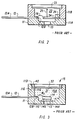
- FIG. 2 is a cross-section through a solid state pressure sensing element comprising a body 11 having upper and lower parts 11a and 11b, leads 12 having external portions 12a and internal portions 12b, and a bar shaped semiconductor sensing element 24 which is attached at one end to body 11 by clamp means 26 and connected to leads 12 via wirebonds 16.
- a prefabricated metal diaphragm 23 separates cavity 22 containing sensing element 24 from the external process media having a pressure measurand to be measured. Hole 13 allows a reference pressure to be communicated to cavity 22 when such is desired.
- Rigid bar or rod 25 provides mechanical coupling between the center of a Prefabricated metal diaphragm 23 and semiconductor sensing element 24.
- FIG. 2 While the configuration of FIG. 2 protects sensing element 24 from the process media whose pressure is intended to be measured, the arrangement of FIG. 2 is expensive to manufacture because of the small piece parts which must be individually handled and precisely located within body 11, and it is also comparatively fragile. It is well known, for example, that semiconductor pressure sensing elements may be extremely brittle. In order to have high sensitivity in the arrangement of FIG. 2, cantilever bar shaped element 24 must be directly coupled via rod 25 to diaphragm 23. Over-pressure conditions applied to diaphragm 23 can readily cause catastrophic failure of sensing element 24. A further disadvantage of the structure of FIG. 2 is that the sensitivity and calibration of the sensor depend critically upon the placement of bar 25 on sensing element 24 and diaphragm 23. A further problem with the arrangement of FIG. 2 is that the active regions of sensing element 24 are exposed to the reference ambient entering via hole 13.
- the prior art solid state sensor comprises body 11 having leads 12 with external portions 12a and internal portions 12b.
- Semiconductor sensing element 14 having reference pressure receiving region 14x is mounted by means 14a on surface llc in cavity 15 of body 11 over hole 13.
- Wirebonds 16 are used for coupling the active regions of sensor 14 to leads 12.
- the upper surface of sensor element 14 may be covered with conventional die coat (not shown). However, this is not essential and the die coat may be omitted.
- Body 11 conveniently extends to the open end of cavity 15 containing sensing element 14.
- Sensing element 14 may be sealed to surface 11c by any convenient means 14a well known in the art. Organic adhesives are a suitable sealing means.
- the reference pressure entering via hole 13 acts only on portion 14x of sensor 14 and does not enter cavity 15.
- ′764 teaches that the lower portion 15a of cavity 15 is to be filled with pressure transfer medium 31.
- An example of a suitable material is given in the reference as Visilox type 191 silastic manufactured by the Visilox Company of Troy, NY.
- Visilox type 191 silastic manufactured by the Visilox Company of Troy, NY.
- approximately 40 percent by volume of titanium dioxide may be mixed into the Visilox 191 material prior to its being introduced into cavity 15, but this is not essential when the preformed diaphragm is opaque. It is stated to be important that upper surface of material 31 extends at least above lip 11e.
- the Visilox 191 material After being placed into portion 15a of cavity 15, the Visilox 191 material is to be vacuum cured.
- Membrane 32 must be flexible and substantially impermeable to the process media of interest even after curing.
- membrane or diaphragm 32 be applied to pressure transfer material 31 in such a way that substantially no air pockets or other voids are trapped within medium 31. This is very difficult to accomplish. If significant voids or pockets are present, the sensitivity and linearity of the pressure transducer will be adversely affected. Substantially void-free application of membrane 32 may allegedly be accomplished as illustrated in FIG. 3, in which a first portion of membrane 32 is placed in contact with a portion of shelf or lip 11e where the transfer medium meets shelf 11e. Prefabricated membrane 32 is then rolled across opening 15 away from the starting location to enclose the cavity 15. It is stated that in the process of rolling out diaphragm 32 it is necessary to push ahead of the unrolling diaphragm a "bow-wave" of material 31 which allegedly fills in any exposed empty places or voids within cavity portion 15.
- membrane 32 may be of any convenient flexible impermeable material. Fluorosilicone is cited as an example of a suitable material for membrane 32.
- FIG. 4 shows a simplified schematic cross-sectional view of a solid state measurand sensor, similar to FIG. 3, but made according to the present invention.
- solid state sensor 10 comprises body 11 having leads 12 with portions external to the body 11 and other portions extending into the cavity 15 of the body 11.
- Semiconductor sensing element 14 having a reference pressure receiving region is mounted by known means on an exposed surface in cavity 15 of body 11 over hole 13. Wires 18 are used for coupling the active regions of sensor 14 to leads 12 where they are conventionally bonded.
- the upper surface of sensor element 14 may be covered with conventional die coat (not shown). However, this is not essential and the die coat may be omitted.
- Body 11 conveniently extends to the open end of cavity 15 containing sensing element 14.
- Sensing element 14 may be sealed to the exposed surface by any convenient means known in the art, including organic adhesives.
- the reference pressure entering via aperture 13 acts only on a portion of sensor 14 and does not enter cavity 15.
- lower portion 15a of cavity 15 is at least partially filled with a pressure transfer medium 31. It is important that during filling of lower portion 15a of cavity 15 with material 31 that trapped gas pockets or enclosed voids be avoided as much as possible. This is conveniently accomplished by using a material for pressure transfer medium 31 which has a low viscosity at the time of introduction. It need not fully cure. A measured amount of material 31 is deposited on and/or around die 14 within the header or body 11 cavity 15 to flow into and fill lower portion 15a of cavity 15. It is important that upper surface of material 31 extend at least above the die 14.
- Medium 31 may be of any convenient material which does not contaminate sensor element 14, which remains in a liquid or at least gel-like or elastic form after introduction and curing of subsequent layers. If a material is used which sets up or becomes hard, then the measurand signal which will subsequently be applied to diaphragm 32 will be attenuated or skewed with temperature excursions before reaching sensor element 14 and the finished device 10 will be insensitive or inaccurate.
- the gel may be evacuated to reduce voids.
- More elastic materials can also be used. If the material 31 is at least partially cured after being introduced into cavity 15, then the needed elasticities apply after curing.
- a suitable material is fluorosilicone dielectric gel, such as Dow-Corning part number X3-6679.
- An opaque diaphragm material may be used as a light blocker, or the transfer medium may be opaque. In order to make the transfer medium material opaque to light, a portion of titanium dioxide or equivalent may be mixed into the pressure transfer material prior to its being introduced into cavity 15, but this is not essential when the diaphragm is opaque. After being placed into portion 15a of cavity 15, the material 31 may be cured following the manufacturer's recommendations. Those of skill in the art will know the appropriate materials curing cycles.
- Another method is to provide an initial fill of material 31 approximately to the level of cure the initial fill, as described above, and then prior to pouring membrane 32, a small amount of the material 31 or other liquid is added to bring the level back up to or slightly above the desired level for material 31.
- pressure transfer medium 31 it is desired to cover pressure transfer medium 31 with pour-in-place membrane 32 such as is shown in FIG. 4.
- the pressure transfer material provides support for the diaphragm.
- Pourable membrane 32 must be flexible and substantially impermeable to the process media of interest, even after curing.
- substitution of a poured-in-place diaphragm for a prefabricated diaphragm is an important variation from the prior art processes for making sensors.
- membrane or diaphragm 32 be deposited on the transfer material 31 in such a way that substantially no air pockets or other voids are trapped within medium 31. With significant voids or pockets present, the sensitivity and linearity of the pressure transducer will be adversely affected. Substantially void-free application of membrane 32 may be conveniently accomplished by the method illustrated in FIG. 4, in which a pourable, viscous membrane 32 material is poured in contact with the transfer medium, filling in any exposed empty places or voids within cavity portion 15a, e.g., such as are illustrated at location 15v in FIG. 4. Evacuating may be used to ensure voids are eliminated. Different viscosity materials may eliminate void reducing steps. Note that it may be desirable for formed-in-place membrane 32 to extend above the face surface of the header in some applications, may be level in others, or may be insufficient to extend beyond the header surface in others. These variations are difficult or impossible with the prior art methods.
- Membrane 32 may be of any suitable and convenient flexible impermeable material which is conveniently pourable. Fluorosilicone is an example of a suitable material for membrane 32. Medical grade RTV type materials permit contact with bodily fluids in medical applications. It is important that membrane 32 be flexible after curing since if it is stiff, the pressure signal will be attenuated prior to reaching sensor element 14. Curing should be complete and not continue after manufacture and installation. Thicknesses for membrane 32 in the range 0.001 to 0.10 (25»m to 2.5mm) may be useful, 0.01 to 0.10 inches (0.25-2.5mm) are more useful, with 0.02 to 0.05 inches (0.5-1.2mm) being preferred.
- Pressure sensors according to the present invention were constructed wherein body 11 was circular and in which the initial aperture for cavity 15 had a minor diameter of approximately 0.22 inches (5.6mm), and the chip or die 14 had a mounting area diameter of approximately 0.15 inches (3.8mm).
- a fluorosilicone diaphragm having an outer diameter corresponding approximately to the size of the body face opening (i.e., the cavity major diameter) was poured in place over pressure transfer medium 31 as described above. In one case the major diameter was about 0.48 inches (12mm). It was determined that the sensitivity of the resulting unit was substantially the same with and without membrane 32. There was no hysteresis.
- the fluorosilicone used was X3-6679 type material manufactured by Down-Corning of Midland, Michigan.
- This fluorosilicone material is particularly soft and flexible. If a harder or denser membrane material is desired to be used, then the thickness of the membrane should be correspondingly reduced in order to maintain about the same sensitivity. It is desirable that the thickness of different membrane materials be adjusted approximately inversely proportional to their relative hardness; this being dependent on the intended application and being within the skill of one of ordinary skill within the art.
- the pressure transfer medium (gel) and the poured-in-place diaphragm are of dissimilar materials, preferably both chemically inert and/or mutually incompatible.
- a dimethyl silicone gel is preferred with a fluorosilicone diaphragm
- a fluorosilicone gel is preferred with a dimethyl silicone diaphragm material.
- Dimethyl silicone gels in combination with dimethyl silicone diaphragms (and fluorosilicone/fluorosilicone) should be avoided, absent some means to prevent chemical interaction between the gel and diaphragm. Skilled artisans in this field will recognize that each diaphragm material has beneficial uses.
- sensing elements may be used in connection with the means and methods of the present invention, and further that a wide variety of pressure transfer materials may be employed provided they are sufficiently liquid to be applied substantially void-free in filling cavity portion 15a, and sufficiently elastic after introduction (and curing) to transmit the pressure applied to membrane 32 to sensor 14 without significant attenuation or hysteresis.
- membrane materials may be used provided they are substantially impermeable to the ambient or process media whose pressures are intended to be measured and sufficiently flexible to be applied by the methods described herein and to avoid attenuation of the pressure signal. Accordingly, the appended claims are intended to include all such reasonable variations in materials.
Landscapes
- Physics & Mathematics (AREA)
- General Physics & Mathematics (AREA)
- Chemical & Material Sciences (AREA)
- Analytical Chemistry (AREA)
- Measuring Fluid Pressure (AREA)
- Electrical Discharge Machining, Electrochemical Machining, And Combined Machining (AREA)
- Glass Compositions (AREA)
- Pressure Sensors (AREA)
Claims (26)
- Verfahren zur Herstellung eines durch eine Membran umwelt- oder umgebungsgeschützten Drucksensors, umfassend folgende Schritte: Vorsehen eines Körpers (11), der in einer ersten Fläche desselben einen Hohl- oder Innenraum ((15) aufweist, welcher Innenraum eine erste Innenfläche zum Aufnehmen eines Drucksensorelements (14) und eine zweite, im wesentlichen aufwärts weisende Fläche zur Halterung der Membran (32) aufweist; Anbringen des Drucksensorelements (14) an der ersten Fläche; und Ausfüllen zumindest eines Teils des Innenraums um das Drucksensorelement herum mit einem Volumen eines Druckübertragungsmaterials (31), welches Volumen kleiner ist als das Volumen des sich unter die Körperoberfläche erstreckenden Innenraums und das Volumen des Sensorelements ausschließt, dadurch gekennzeichnet, daß ein für das Verschließen des Innenraums ausreichendes Volumen eines flexiblen, direkt (an Ort und Stelle) vergießbaren Membranmaterials über dem Druckübertragungsmaterial gegossen wird, wobei das Membranmaterial und das Druckübertragungsmaterial chemisch inkompatibel sind.
- Verfahren nach Anspruch 1, dadurch gekennzeichnet, daß die Membran in Abwesenheit einer wesentlichen Membranmaterialschrumpfung nahe oder an der zweiten Fläche geformt wird.
- Verfahren nach Anspruch 1, dadurch gekennzeichnet, daß das direkt vergießbare Membranmaterial ein fließfähiger polymerer Stoff ist.
- Verfahren nach Anspruch 2, dadurch gekennzeichnet, daß der Schritt des Vergießens des flexiblen Membranmaterials das Vorsehen oder Ausbilden einer Membran umfaßt, die aus einem Fluorsilikonmaterial, welches nach dem Verfestigen im wesentlichen sein ursprüngliches Volumen beibehält, gegossen wird.
- Verfahren nach Anspruch 2, dadurch gekennzeichnet, daß der Schritt des Vergießens des flexiblen Membranmaterials das Vorsehen oder Ausbilden einer Membran umfaßt, die aus einem Dimethylsilikonmaterial, das nach dem Verfestigen im wesentlichen sein ursprüngliches Volumen beibehält, gegossen wird.
- Verfahren nach Anspruch 2, dadurch gekennzeichnet, daß der Schritt des Vergießens des flexiblen Membranmaterials das Vorsehen oder Ausbilden einer Membran umfaßt, die aus einem Silikon-"Gummi"-Material eines medizinischen Gütegrads, das nach dem Verfestigen im Wesentlichen sein ursprüngliches Volumen beibehält, gegossen wird.
- Verfahren nach Anspruch 1, dadurch gekennzeichnet, daß es den Schritt eines Testens des Drucksensorelements vor dem Ausfüllen des Innenraums beinhaltet.
- Verfahren nach Anspruch 7, dadurch gekennzeichnet, daß es die Schritte eines Einstellens (Justierens) des Sensorelements und eines Eichens (Abgleichens) des Druck(sensor)elements vor dem Verschließen des Innenraums umfaßt.
- Verfahren nach Anspruch 1, dadurch gekennzeichnet, daß die Innenraummaße so gewählt werden, daß minimale Füllvolumina gewährleistet sind.
- Verfahren nach Anspruch 1, dadurch gekennzeichnet, daß die zweite, im wesentlichen aufwärts weisende Fläche umfangsmäßig eine erste Ausnehmung eines gegebenen Querschnitts bodenseitig begrenzt (bottoms) und eine zweite, von der ersten Ausnehmung abgehende Ausnehmung eines kleineren Querschnitts als bei der ersten Ausnehmung bodenseitig im wesentlichen durch die erste Innenfläche zur Halterung des Drucksensor-elements (14) begrenzt ist, so daß die erste und die zweite Ausnehmung den Innenraum (15) als abgestuften Hohl- oder Innenraum in der Körperstirnfläche bilden; wobei das Ver-fahren ferner die Herstellung elektrischer Anschlüsse (18) am Drucksensorelement umfaßt; das Druckübertragungsmaterial (31) ein nichtgasförmiges oder nichtgasendes, die zweite Ausnehmung praktisch ausfüllendes Druckübertragungsmedium ist; und das flexible Membranmaterial (32) in Berührung mit dem Druckübertragungsmedium und mit der zweiten Fläche (ein)gegossen wird und so gewählt ist, daß es beim Aushärten desselben nicht schrumpft.
- Drucksensor, umfassend:(a) einen Körper (11) mit einer in einer ersten Stirnfläche desselben vorgesehenen ersten Ausnehmung eines gegebenen Querschnitts, die umfangsmäßig von einem Mittel zur Halterung einer Membran (32), bestehend aus einer ersten aufwärts weisenden Fläche, bodenseitig begrenzt (bottomed) wird, und einer zweiten, gegenüber der ersten Ausnehmung versetzten Ausnehmung, die einen kleineren Querschnitt als die erste Ausnehmung aufweist und im wesentlichen durch eine zweite aufwärts weisende Fläche zur Halterung eines Drucksensorelements (14) bodenseitig begrenzt wird, wobei erste und zweite Ausnehmung in der Körperstirnfläche einen einheitlichen (gemeinamen) Hohl- oder Innenraum (15) bilden,(b) in den Innenraum führende elektrische Signalübertragungswege (18, 12) und(c) ein mit den Übertragungswegen verbundenes Drucksensorelement, wobei der Sensor gekennzeichnet ist durch(d) eine direkt (an Ort und Stelle) gegossene, nichthärtende flexible Membran (32) und(e) Mittel zum (1) Isolieren des Sensorelements gegenüber dem zu messenden Druck, (2) Übertragen des Drucks auf das Sensorelement und (3) Haltern oder Tragen der Membran, bestehend aus einem nichthärtenden Druckübertragungsmedium (31),wobei das Druckübertragungsmedium und das Membranmaterial beide ungebunden oder unverklebt und chemisch inkompatibel sind und das Druckübertragungsmedium und das Membranmaterial den zu messenden Druck auf das Sensorelement zu übertragen vermögen.
- Sensor nach Anspruch 11, dadurch gekennzeichnet, daß das Druckübertragungsmedium ein Material auf Dimethylsilikonbasis ist.
- Sensor nach Anspruch 11, dadurch gekennzeichnet, daß das Druckübertragungsmedium ein Fluorsilikonmaterial ist.
- Sensor nach Anspruch 11, dadurch gekennzeichnet, daß das Membranmaterial ein Material auf Fluorsilikonbasis ist.
- Sensor nach Anspruch 11, dadurch gekennzeichnet, daß das Membranmaterial ein Material auf Dimethylsilikonbasis ist.
- Sensor nach Anspruch 12, dadurch gekennzeichnet, daß er ferner ein (optisch) undurchlässig machendes Mittel zum Isolieren des Sensorelements gegenüber Licht enthält.
- Sensor nach Anspruch 11, dadurch gekennzeichnet, daß er ferner ein Mittel zum Übertragen einer zweiten Meßgröße zum Meßelement (Sensorelement) aufweist.
- Sensor nach Anspruch 11, dadurch gekennzeichnet, daß das Meßelement ein Festkörper-Sensorelement ist.
- Sensor nach Anspruch 11, dadurch gekennzeichnet, daß die erste Ausnehmung einen größeren Querschnitt als die zweite Ausnehmung aufweist.
- Sensor nach Anspruch 11, dadurch gekennzeichnet, daß die erste Ausnehmung ein kleineres Volumen als die zweite Ausnehmung aufweist.
- Sensor nach Anspruch 11, dadurch gekennzeichnet, daß das Volumen der ersten Ausnehmung im wesentlichen das Membranmaterial enthält oder beinhaltet.
- Sensor nach Anspruch 11, dadurch gekennzeichnet, daß die erste Ausnehmung eine das Membranmaterial abstützende Teilbodenfläche aufweist.
- Sensor nach Anspruch 11, dadurch gekennzeichnet, daß die Membran eine im wesentlichen undurchlässige Sperre mit einer auswärts weisenden Fläche und einer einwärts weisenden und durch das Druckübertragungsmedium und an ihrem Umfang durch die erste aufwärts weisende Fläche unterstützten Fläche bildet.
- Sensor nach Anspruch 11, dadurch gekennzeichnet, daß die auswärts weisende Fläche unter die erste aufwärts weisende Fläche des Körpers vertieft angeordnet ist.
- Sensor nach Anspruch 17, dadurch gekennzeichnet, daß das Mittel zum Übertragen einer zweiten Meßgröße zum Meßelement eine Bohrung in der zweiten aufwärts weisenden Fläche und einen Verbindungsdurchgang in die zweite Ausnehmung umfaßt.
- Sensor nach Anspruch 11, dadurch gekennzeichnet, daß das Membranmaterial eine im wesentlichen undurchlässige Sperre mit einer auswärts weisenden Fläche und einer einwärts weisenden Fläche, die an ihrem Zentrum dem Druckübertragungsmaterial zugewandt und durch dieses unterstützt und an ihrem Umfang durch die aufwärts weisende Fläche unterstützt ist, bildet, wobei die auswärts weisende Fläche im wesentlichen in einer Ebene mit der ersten Fläche des Körpers liegt.
Applications Claiming Priority (3)
| Application Number | Priority Date | Filing Date | Title |
|---|---|---|---|
| US16359888A | 1988-03-03 | 1988-03-03 | |
| US163598 | 1988-03-03 | ||
| PCT/US1989/000823 WO1989008244A1 (en) | 1988-03-03 | 1989-03-03 | Protected pressure sensor |
Publications (3)
| Publication Number | Publication Date |
|---|---|
| EP0400074A1 EP0400074A1 (de) | 1990-12-05 |
| EP0400074A4 EP0400074A4 (en) | 1992-02-05 |
| EP0400074B1 true EP0400074B1 (de) | 1994-09-28 |
Family
ID=22590730
Family Applications (1)
| Application Number | Title | Priority Date | Filing Date |
|---|---|---|---|
| EP89903349A Expired - Lifetime EP0400074B1 (de) | 1988-03-03 | 1989-03-03 | Geschützter drucksensor |
Country Status (6)
| Country | Link |
|---|---|
| EP (1) | EP0400074B1 (de) |
| JP (1) | JPH02503828A (de) |
| AT (1) | ATE112389T1 (de) |
| CA (1) | CA1324892C (de) |
| DE (1) | DE68918584T2 (de) |
| WO (1) | WO1989008244A1 (de) |
Cited By (2)
| Publication number | Priority date | Publication date | Assignee | Title |
|---|---|---|---|---|
| DE19840829B4 (de) * | 1998-09-07 | 2005-10-20 | Siemens Ag | Verfahren zum Befestigen eines mikromechanischen Sensors in einem Gehäuse und Sensoranordnung |
| EP4502563A1 (de) * | 2023-08-01 | 2025-02-05 | Honeywell International Inc. | Flüssigkeitskupplungsmedium zur verwendung in einem medienisolierten drucksensor |
Families Citing this family (7)
| Publication number | Priority date | Publication date | Assignee | Title |
|---|---|---|---|---|
| DE4023420A1 (de) * | 1990-07-24 | 1992-01-30 | Pfister Gmbh | Drucksensor |
| US6453749B1 (en) | 1999-10-28 | 2002-09-24 | Motorola, Inc. | Physical sensor component |
| US6769319B2 (en) | 2001-07-09 | 2004-08-03 | Freescale Semiconductor, Inc. | Component having a filter |
| US20050124896A1 (en) * | 2003-08-25 | 2005-06-09 | Jacob Richter | Method for protecting implantable sensors and protected implantable sensors |
| US8162839B2 (en) | 2003-08-27 | 2012-04-24 | Microtech Medical Technologies Ltd. | Protected passive resonating sensors |
| DE102004012059A1 (de) * | 2004-03-11 | 2005-10-06 | Siemens Ag | Verfahren zum Herstellen eines Körpers |
| JP5710310B2 (ja) * | 2011-02-18 | 2015-04-30 | アルプス電気株式会社 | 荷重センサを用いた圧力測定装置 |
Family Cites Families (8)
| Publication number | Priority date | Publication date | Assignee | Title |
|---|---|---|---|---|
| GB2096825A (en) * | 1981-04-09 | 1982-10-20 | Sibbald Alastair | Chemical sensitive semiconductor field effect transducer |
| JP2504737B2 (ja) * | 1985-07-19 | 1996-06-05 | シチズン時計株式会社 | 圧力センサユニツト |
| US4655088A (en) * | 1985-10-07 | 1987-04-07 | Motorola, Inc. | Unibody pressure transducer package |
| US4686764A (en) * | 1986-04-22 | 1987-08-18 | Motorola, Inc. | Membrane protected pressure sensor |
| US4732042A (en) * | 1986-04-22 | 1988-03-22 | Motorola Inc. | Cast membrane protected pressure sensor |
| US4691573A (en) * | 1986-06-16 | 1987-09-08 | Fisher Controls International, Inc. | Pressure sensor |
| USH606H (en) * | 1987-11-27 | 1989-03-07 | Motorola, Inc. | Pressure sensor assembly |
| JPH05225680A (ja) * | 1992-02-10 | 1993-09-03 | Matsushita Electric Ind Co Ltd | 磁気ディスク装置 |
-
1989
- 1989-03-03 DE DE68918584T patent/DE68918584T2/de not_active Expired - Fee Related
- 1989-03-03 WO PCT/US1989/000823 patent/WO1989008244A1/en not_active Ceased
- 1989-03-03 JP JP1503149A patent/JPH02503828A/ja active Pending
- 1989-03-03 AT AT89903349T patent/ATE112389T1/de not_active IP Right Cessation
- 1989-03-03 EP EP89903349A patent/EP0400074B1/de not_active Expired - Lifetime
- 1989-03-03 CA CA000592743A patent/CA1324892C/en not_active Expired - Fee Related
Non-Patent Citations (1)
| Title |
|---|
| US H H 606 * |
Cited By (2)
| Publication number | Priority date | Publication date | Assignee | Title |
|---|---|---|---|---|
| DE19840829B4 (de) * | 1998-09-07 | 2005-10-20 | Siemens Ag | Verfahren zum Befestigen eines mikromechanischen Sensors in einem Gehäuse und Sensoranordnung |
| EP4502563A1 (de) * | 2023-08-01 | 2025-02-05 | Honeywell International Inc. | Flüssigkeitskupplungsmedium zur verwendung in einem medienisolierten drucksensor |
Also Published As
| Publication number | Publication date |
|---|---|
| DE68918584D1 (de) | 1994-11-03 |
| ATE112389T1 (de) | 1994-10-15 |
| WO1989008244A1 (en) | 1989-09-08 |
| EP0400074A4 (en) | 1992-02-05 |
| DE68918584T2 (de) | 1995-01-26 |
| CA1324892C (en) | 1993-12-07 |
| EP0400074A1 (de) | 1990-12-05 |
| JPH02503828A (ja) | 1990-11-08 |
Similar Documents
| Publication | Publication Date | Title |
|---|---|---|
| US4993265A (en) | Protected pressure sensor and method of making | |
| US4686764A (en) | Membrane protected pressure sensor | |
| US4732042A (en) | Cast membrane protected pressure sensor | |
| US4842685A (en) | Method for forming a cast membrane protected pressure sensor | |
| JP4726481B2 (ja) | 気圧センサ | |
| US4656454A (en) | Piezoresistive pressure transducer with elastomeric seals | |
| EP0767899B1 (de) | Verfahren zum einbau eines absolutdrucksensors | |
| EP2505981B1 (de) | Absolut kapazitativer Mikrodrucksensor | |
| US6401545B1 (en) | Micro electro-mechanical system sensor with selective encapsulation and method therefor | |
| US5438876A (en) | Modular diaphragm pressure sensor with peripheral mounted electrical terminals | |
| US6351996B1 (en) | Hermetic packaging for semiconductor pressure sensors | |
| US6255728B1 (en) | Rigid encapsulation package for semiconductor devices | |
| JP4550364B2 (ja) | 半導体圧力センサ | |
| US8631708B2 (en) | Apparatus and method for minimizing drift of a piezo-resistive pressure sensor due to the progressive release of mechanical stress over time | |
| EP0545319B1 (de) | Halbleiter-Druckwandler mit zwei Membranen | |
| US5029478A (en) | Fluid isolated self-compensating absolute pressure sensor transducer | |
| EP0400074B1 (de) | Geschützter drucksensor | |
| EP1055106A2 (de) | Medienkompatible gehäuse für drucksensor-vorrichtungen | |
| JPH1068666A (ja) | 圧力差検出装置及びその製造方法 | |
| US5741975A (en) | Media isolated differential pressure sensor and fluid injection method | |
| EP1601942B1 (de) | Silizium-drucksensor mit niedrigem druckausgleich zwischen dem gemessenen druck und dem referenzraum | |
| US6591686B1 (en) | Oil filled pressure transducer | |
| JP3892065B2 (ja) | センサ装置及びセンサチップの固着方法 | |
| CN215492215U (zh) | 介质隔离式压力传感器 | |
| JPH05133827A (ja) | 半導体圧力センサ |
Legal Events
| Date | Code | Title | Description |
|---|---|---|---|
| PUAI | Public reference made under article 153(3) epc to a published international application that has entered the european phase |
Free format text: ORIGINAL CODE: 0009012 |
|
| 17P | Request for examination filed |
Effective date: 19900220 |
|
| AK | Designated contracting states |
Kind code of ref document: A1 Designated state(s): AT BE CH DE FR GB IT LI LU NL SE |
|
| A4 | Supplementary search report drawn up and despatched |
Effective date: 19911213 |
|
| AK | Designated contracting states |
Kind code of ref document: A4 Designated state(s): AT BE CH DE FR GB IT LI LU NL SE |
|
| 17Q | First examination report despatched |
Effective date: 19930122 |
|
| GRAA | (expected) grant |
Free format text: ORIGINAL CODE: 0009210 |
|
| AK | Designated contracting states |
Kind code of ref document: B1 Designated state(s): AT BE CH DE FR GB IT LI LU NL SE |
|
| PG25 | Lapsed in a contracting state [announced via postgrant information from national office to epo] |
Ref country code: IT Free format text: LAPSE BECAUSE OF FAILURE TO SUBMIT A TRANSLATION OF THE DESCRIPTION OR TO PAY THE FEE WITHIN THE PRESCRIBED TIME-LIMIT;WARNING: LAPSES OF ITALIAN PATENTS WITH EFFECTIVE DATE BEFORE 2007 MAY HAVE OCCURRED AT ANY TIME BEFORE 2007. THE CORRECT EFFECTIVE DATE MAY BE DIFFERENT FROM THE ONE RECORDED. Effective date: 19940928 Ref country code: NL Effective date: 19940928 Ref country code: BE Effective date: 19940928 Ref country code: CH Effective date: 19940928 Ref country code: LI Effective date: 19940928 Ref country code: AT Effective date: 19940928 |
|
| REF | Corresponds to: |
Ref document number: 112389 Country of ref document: AT Date of ref document: 19941015 Kind code of ref document: T |
|
| REF | Corresponds to: |
Ref document number: 68918584 Country of ref document: DE Date of ref document: 19941103 |
|
| ET | Fr: translation filed | ||
| PG25 | Lapsed in a contracting state [announced via postgrant information from national office to epo] |
Ref country code: SE Effective date: 19941228 |
|
| REG | Reference to a national code |
Ref country code: CH Ref legal event code: PL |
|
| NLV1 | Nl: lapsed or annulled due to failure to fulfill the requirements of art. 29p and 29m of the patents act | ||
| PG25 | Lapsed in a contracting state [announced via postgrant information from national office to epo] |
Ref country code: LU Free format text: LAPSE BECAUSE OF NON-PAYMENT OF DUE FEES Effective date: 19950331 |
|
| PLBE | No opposition filed within time limit |
Free format text: ORIGINAL CODE: 0009261 |
|
| STAA | Information on the status of an ep patent application or granted ep patent |
Free format text: STATUS: NO OPPOSITION FILED WITHIN TIME LIMIT |
|
| 26N | No opposition filed | ||
| REG | Reference to a national code |
Ref country code: GB Ref legal event code: IF02 |
|
| PGFP | Annual fee paid to national office [announced via postgrant information from national office to epo] |
Ref country code: GB Payment date: 20030204 Year of fee payment: 15 |
|
| PGFP | Annual fee paid to national office [announced via postgrant information from national office to epo] |
Ref country code: FR Payment date: 20030303 Year of fee payment: 15 |
|
| PGFP | Annual fee paid to national office [announced via postgrant information from national office to epo] |
Ref country code: DE Payment date: 20030331 Year of fee payment: 15 |
|
| PG25 | Lapsed in a contracting state [announced via postgrant information from national office to epo] |
Ref country code: GB Free format text: LAPSE BECAUSE OF NON-PAYMENT OF DUE FEES Effective date: 20040303 |
|
| PG25 | Lapsed in a contracting state [announced via postgrant information from national office to epo] |
Ref country code: DE Free format text: LAPSE BECAUSE OF NON-PAYMENT OF DUE FEES Effective date: 20041001 |
|
| GBPC | Gb: european patent ceased through non-payment of renewal fee | ||
| PG25 | Lapsed in a contracting state [announced via postgrant information from national office to epo] |
Ref country code: FR Free format text: LAPSE BECAUSE OF NON-PAYMENT OF DUE FEES Effective date: 20041130 |
|
| REG | Reference to a national code |
Ref country code: FR Ref legal event code: ST |