EP0400087B1 - Intelligenter heizblock - Google Patents
Intelligenter heizblock Download PDFInfo
- Publication number
- EP0400087B1 EP0400087B1 EP89904189A EP89904189A EP0400087B1 EP 0400087 B1 EP0400087 B1 EP 0400087B1 EP 89904189 A EP89904189 A EP 89904189A EP 89904189 A EP89904189 A EP 89904189A EP 0400087 B1 EP0400087 B1 EP 0400087B1
- Authority
- EP
- European Patent Office
- Prior art keywords
- temperature
- support
- reaction
- source
- wells
- Prior art date
- Legal status (The legal status is an assumption and is not a legal conclusion. Google has not performed a legal analysis and makes no representation as to the accuracy of the status listed.)
- Expired - Lifetime
Links
Images


Classifications
-
- B—PERFORMING OPERATIONS; TRANSPORTING
- B01—PHYSICAL OR CHEMICAL PROCESSES OR APPARATUS IN GENERAL
- B01L—CHEMICAL OR PHYSICAL LABORATORY APPARATUS FOR GENERAL USE
- B01L3/00—Containers or dishes for laboratory use, e.g. laboratory glassware; Droppers
- B01L3/50—Containers for the purpose of retaining a material to be analysed, e.g. test tubes
- B01L3/508—Rigid containers without fluid transport within
- B01L3/5085—Rigid containers without fluid transport within for multiple samples, e.g. microtitration plates
- B01L3/50853—Rigid containers without fluid transport within for multiple samples, e.g. microtitration plates with covers or lids
-
- B—PERFORMING OPERATIONS; TRANSPORTING
- B01—PHYSICAL OR CHEMICAL PROCESSES OR APPARATUS IN GENERAL
- B01L—CHEMICAL OR PHYSICAL LABORATORY APPARATUS FOR GENERAL USE
- B01L7/00—Heating or cooling apparatus; Heat insulating devices
- B01L7/52—Heating or cooling apparatus; Heat insulating devices with provision for submitting samples to a predetermined sequence of different temperatures, e.g. for treating nucleic acid samples
-
- G—PHYSICS
- G05—CONTROLLING; REGULATING
- G05D—SYSTEMS FOR CONTROLLING OR REGULATING NON-ELECTRIC VARIABLES
- G05D23/00—Control of temperature
- G05D23/19—Control of temperature characterised by the use of electric means
- G05D23/1919—Control of temperature characterised by the use of electric means characterised by the type of controller
Definitions
- This invention relates to apparatus for and a method of controlling the temperature of a reaction zone.
- the invention is primarily concerned with controlling the temperature of biological reactions, but is not restricted to such reactions and for simplicity details of specific biological or chemical reactions are not specifically referred to in the ensuing description or the appendent claims.
- US 4 429 829 shows a temperature control system for a given area, for example is an incubator, in which a heating and cooling device is operated in response to signals from temperature probes in said area.
- the heating and cooling device relies on the circulation of air through the area in order to achieve both heating and cooling of the area, and also cannot rapidly change (particularly increase) the temperature of reagents in the area.
- apparatus for controlling the temperature of a plurality of reaction sites on a support
- the apparatus comprising reaction temperature sensing means, a microprocessor responsive to the output of the temperature sensing means, control means responsive to output signals from the microprocessor to control the operation of heating means operable to raise the temperature of the sites, and cooling means for reducing the temperature of the sites, said control being such as to cause said temperature to conform to a required temperature/time profile, characterised in that the heating means comprises a source of radiant energy, and the cooling means comprises a fan, and in that the support comprises a metal plate for evenly distributing heat derived from the source to the reaction sites, which comprise a plurality of wells in the support.
- a method of controlling the temperature of a plurality of reaction sites according to which said temperature is sensed by at least one temperature sensor, and a temperature/time profile is set by a programmed microprocessor, the temperature being caused to conform to the profile by heating means for raising the temperature, and by cooling means for reducing the temperature, on/off switching of the source and of the cooling means being controlled by control means which itself is controlled by the microprocessor which is in turn supplied by signals from the temperature sensor, characterised in that the heating means comprises a source of radiant energy, the cooling means comprises a fan, and in that heat from the source is evenly distributed among the sites by means of a metal plate which comprises a support having a plurality of wells each defining a respective reaction site.
- the apparatus and method above described are especially useful for temperature control of biological reactions as a polymerase chain reaction for DNA amplification or an enzyme mediated DNA modification reaction but the invention may be employed for any reaction zone temperature control whether the reaction to one of the biological or molecular biological or general chemical nature.
- the wells may be formed as cups in the metal plate itself, so that reaction tubes such as "Eppendorf” tubes can be fitted into the cups.
- the wells may be embedded in a tray, for example of plastics material, which seats on the metal plate, the metal plate being provided with through apertures to accommodate the wells.
- At least the bases of the wells may be transparent and if supported by a metal plate the latter is apertured to allow the wells to protrude downwardly therethrough.
- the radiation can be arranged to be incident directly on the underside of the transparent wells, thereby to heat the reactants directly.
- An apertured shade may be provided, movable to adjust the amount of direct radiation received by the reactants. When maximum heating is required, direct radiation may be maximised. For lesser heating direct radiation may be excluded, and reliance placed on heating by conductivity through the shade.
- the shade is preferably formed from a thermally conductive material such as copper or other thermally conductive material and be slidably located directly against the metal plate.
- the underside of the wells and the apertured plate conveniently occupy the same plane and the shade is a second apertured plate of metal in sliding contact with the underside of the apertured metal plate.
- the support, the source and the fan are accommodated in a housing having an air inlet and an air outlet.
- the source is located within the housing, and is preferably housed at the base of a reflective shield acting to direct radiation from the source toward the support for the reactants.
- the shield is preferably closed at the end adjacent the support by a transparent plate typically of a ceramic material.
- further air flow directing means in the housing ensure that the fan, when operable, causes a turbulent stream of cooling air to pass in contact with the support, in passage from the housing inlet to the housing outlet.
- the source is preferably a quartz-halogen lamp emitting both visible and infra-red radiation.
- the sensor may sense the temperature of the support and/or that of one or more reaction sites, the microprocessor being programmed to anticipate the time lag between the support temperature and the reaction temperature if only the support is sensed.
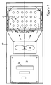
- a main housing 10 accommodates a quartz-halogen lamp 12, a fan 14 and a metal support 16 for reactants, for example contained in reaction tubes seated in wells 17 in the support plate.
- a sub-housing 18 accommodating a programmable microprocessor and associated electronics on printed circuit boards 20.
- a reaction temperature sensor 22 Associated with the support 16 is a reaction temperature sensor 22.
- the operation of the lamp 12 and fan 14 are controlled by suitable control means such as isolating relays 24 fed with control signals from the microprocesor, which is programmed to respond to signals received from the reaction temperature sensor 22 in order to cause the reaction temperature of the reaction tubes carried by the support 16 to follow a required temperature/time profile.
- suitable control means such as isolating relays 24 fed with control signals from the microprocesor, which is programmed to respond to signals received from the reaction temperature sensor 22 in order to cause the reaction temperature of the reaction tubes carried by the support 16 to follow a required temperature/time profile.
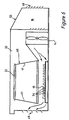
- FIG 3 there is shown one embodiment of the invention wherein, for convenience, the same reference numerals as in Figures 1 and 2 are employed for similar parts.
- the support 16 comprise a plate of copper or other thermally conductive metal of low thermal capacity and good thermal conductivity.
- the metal plate 16 is formed with twenty four cups or wells 17 in a 6 by 4 array, shaped closely to receive the lower ends of sealed Eppendorf reaction tubes 25.
- Above the plate 16, the tubes 25 are laterally supported by apertures in a block 27 of thermally insulating material such as polyethylene which is let into the top wall of the housing 10.
- the quartz-halogen lamp 12 is accommodated at the bottom of a shield 28 of aluminium, with polished internal walls, whereby radiation from the lamp is concentrated on to the undersurface of the metal support plate 16.
- a ramp surface 30 is provided in the housing 10, whereby when the fan is operating, the air is caused to flow in turbulent manner, as indicated by the arrow 31, past the support plate 16.
- Sub-housing 18 again accommodates the programmable microprocessor and associated electronics including isolating relays for switching the lamp and the fan on and off.
- the upper surface 32 of the sub-housing 18 is conveniently formed as a desk-top carrying a keypad for selecting the microprocessor program and a display unit such as an LCD display.
- a reaction temperature sensor 22 is provided in the support plate 16, and if desired a second such sensor 22A may be provided in contact with one of the reaction tubes 25.
- a sensor will hereinafter be referred to as a "phial" sensor.
- switching on and off of the lamp and the fan is controlled by the microprocessor, responsively to signal from either one or both of the reaction temperature sensors, to produce a required temperature/time profile for the reaction taking place in the reaction tubes.
- the insulation 27 reduces loss of heat from the support plate 16 and protects the operator against burning when handling the reaction tubes.
- the support here includes a thin plastics tray 33 of rectangular shape.
- the tray 33 is integrally formed with a column/row array of cups or wells 34 which may be designed to accommodate reaction tubes, such as "Eppendorf” reaction tubes, which may be formed from polypropylene or alternatively the tray 33 may constitute a welled reaction dish.
- the plastics tray 33 seals onto a thin thermally conductive copper plate 35 drilled or otherwise formed with through-apertures to accommodate and fit closely around the lower ends of the wells 34.
- the two part support 33, 35 is mounted in the housing 10 just below an openable lid 36, hinged at 37 at one end to the housing and openable about the hinge 37 by means of a handle 38 at the other end, in order to give access to the support.
- the lid 36 is double-walled, and contains thermal insulation material, for example of sheet polypropylene. When the lid is closed, a relatively narrow space or passage 39 exists between the underside of the lid 36 and the support plate 35.
- the quartz halogen lamp 12 is again mounted near the base of the housing 10 beneath the support, in operation to emit visible and infra-red radiation towards the underside of the support in order to effect heating thereof, and thereby heat reactants carried by the reaction tray 33.
- the lamp 12 is mounted at the base of an upstanding aluminium shield 40 with polished interior surfaces 41 whereby loss of radiation from the lamp is minimised.
- the shield 40 is optionally closed at the top, just beneath the underside of the support 33,35 by a transparent ceramic plate 42.
- the lamp 12, shield 40 and ceramic plate 42 in combination define the shape of a truncated pyramid, base uppermost.
- a space or passage 43 exists between the ceramic plate 42 and the underside of the support 33, 35.
- an apertured plate of copper 44 is mounted immediately beneath the support plate 35 to be slidably movable relative thereto, and with a layer of conductive grease therebetween.
- the apertured copper plate 44 is apertured in a row/column array corresponding to that of the reaction sites on the support.
- the support plate 35 comprises a 1mm thick copper sheet drilled or otherwise formed with ninety six apertures in which a corresponding number of reaction wells, (eg wells formed in a transparent polystyrene tray), are received.
- the bottoms of the wells are coplanar with the underside of the plate 35.
- the second copper sheet 44 which may be of similar thickness material, is drilled or otherwise apertured in like manner and is slidable directly beneath and in contact with the plate 35 so that the lower plate is in contact with the upper plate 35 for exposing more or less of the underside of each of the wells to the lamp radiation.
- this arrangement enables the liquid reactants to be directly exposed to the radiation, (through the transparent bases of the wells) whereby rapid heating to a relatively high temperature is possible.
- the undersides of the wells may be shaded, by appropriate sliding of the second sheet so that heating of the reactants occurs partly or wholly by conduction.
- the second sheet may be manually adjustable or, as illustrated, adjustable by a motor 45 which drives a connecting rod 46 via a ratchet device 47.
- the motor 45 may also be employed to drive the fan 14, provided a suitable clutch or other disengagement means is provided.
- the shading plate 44 is moved to fully expose the wells to the lamp radiation and as soon as the desired temperature is attained, is moved out of alignment to hold the temperature achieved.
- the fan 14 draws in environmental air at room temperature through an air inlet, 48 in the top wall of the housing above the fan, and expels air through a louvred outlet 49 on the side of the lamp/shield assembly remote from said fan.
- Figure 5 shows the air holes 50 in the support plate mounting which enable the air to pass into and exit from the ends of the passage 39. The air is thus caused to pass in turbulent flow through the passages 39, 43 above and below the support 33, 35, thereby to effect cooling of the latter and the reactants carried thereby. Air flow within the housing is again generally indicated by the marked arrows.
- the air inlet may alternatively be located on the remote side of the sub-housing.
- the sub-housing 18 contains a microprocessor 51 and associated electronics on a stack 52 of printed circuit boards, and the upper surface 53 of the sub-housing again houses a keypad 54 and an LCD display 56 associated with the microprocessor.
- the microprocessor 51 is able to receive signals output from either one or both of two reaction temperature sensors.
- the sensor 58 senses the reaction zone temperature indirectly by sensing the temperature of the plate 35.
- the sensor 60 senses the reaction temperature directly, for example by dipping into the reactants in a selected sample reaction tube on the support plate.
- the sensors 58, 60 may comprise thermocouples or thermistors of a commercially available kind having appropriate range and sensitivity for the purpose for which they are required.
- the microprocessor 51 responds to the signals from one or the other (or both) of the two temperature sensors to provide switching signals for switching the lamp 12 and the fan 14 on and off, each independently of the other, in order to cause the temperature of the reactants on the support plate to follow a required temperature/time profile.
- This may for example be programmed into the memory of the microprocessor, for example by means of the keypad.
- the microprocessor includes an electronic clock (not shown).
- the required temperature profile may range from a constant temperature to a temperature varying between a plurality of upper and lower values with varying time intervals.
- a temperature profile commonly required for biological reactions involves a temperature cyclically varying between two temperatures with a regular periodicity, as exemplified by Figure 7.
- Figure 6 shows a modified arrangement in which the lamp/shield assembly 12, 40 is inverted and positioned above the support 16, which is accessible through a hatch in the side wall of the housing 10.
- the support 16 may be a welled upper plate as described with reference to Figure 3 or a composite support as described with reference to Figures 4 and 5, and is located on apertured guides which enable turbulant air flow beneath, as well as above the support.
- the housing surface beneath the support plate 16 is reflectively coated.
- the underside of the lid in the embodiment of Figures 4 and 5 may also be reflectively coated.
- Figure 6 is generally similar to that of Figures 4 and 5 and corresponding reference numerals are therefore employed.
- FIG 8 is a block circuit diagram showing the control electronics, in which the same references as in Figures 1 to 3 are employed for correspoding components. Additionally, references 61 and 62 designate the ROM and the non-volatile RAM of the microprocessor 51, respectively, and references 64 and 66 denote an interface between the microprocessor 51 and the display 56 (which with isolators 68 in the form of solid state relays, may be a computer monitor screen), and between the microprocessor 51 and the keypad 54. The interface 66 also connects the microprocessor 51 with isolators 68 in the form of solid state relays, for effecting switching of the lamp 12 and the fan 14, and also with an alarm 70 such as a buzzer operative in the event of a fault.
- the inputs to the microprocessor 51 from the reaction-temperature sensors 58, 60 are supplied via conditioning amplifiers 72 and an analogue to digital converter 74.
- Reed relays may be employed as the isolators 68.
Landscapes
- Chemical & Material Sciences (AREA)
- Health & Medical Sciences (AREA)
- Clinical Laboratory Science (AREA)
- General Health & Medical Sciences (AREA)
- Chemical Kinetics & Catalysis (AREA)
- Physics & Mathematics (AREA)
- Hematology (AREA)
- Life Sciences & Earth Sciences (AREA)
- Biochemistry (AREA)
- Molecular Biology (AREA)
- Analytical Chemistry (AREA)
- General Physics & Mathematics (AREA)
- Engineering & Computer Science (AREA)
- Automation & Control Theory (AREA)
- Automatic Analysis And Handling Materials Therefor (AREA)
- Control Of Temperature (AREA)
- External Artificial Organs (AREA)
- Cookers (AREA)
- Optical Measuring Cells (AREA)
- Medicines Containing Material From Animals Or Micro-Organisms (AREA)
- Crystals, And After-Treatments Of Crystals (AREA)
- Devices For Use In Laboratory Experiments (AREA)
- Treatment Of Sludge (AREA)
Claims (13)
- Gerät zum Regeln der Temperatur einer Vielzahl von Reaktionsorten (17, 34) auf einem Ständer (16, 33, 35) mit einem Reaktionstemperaturmeßmittel (22, 58, 60), einem auf die Ausgabe der Temperaturmeßmittel (22, 58, 60) ansprechenden Mikroprozessor (51), einem auf die Ausgangssignale vom Mikroprozessor (51) ansprechenden Regelmittel (24) zum Steuern des Betriebes eines Heizmittels (12) zum Anheben der Temperatur der Orte (17, 34) und mit einem Kühlmittel (14) zum Herabsetzen der Temperatur der Orte (17, 34), wobei diese Steuerung so beschaffen ist, daß die Temperatur mit einem Temperatur/Zeitsollprofil in Übereinstimmung gebracht wird, dadurch gekenn- zeichnet, daß das Heizmittel eine Strahlungsenergie-Quelle (12) und das Kühlmittel einen Lüfter (14) umfaßt und daß der Ständer eine Metallplatte (16, 35) zur gleichförmigen Verteilung der von der Quelle (12) abgeleiteten Wärme auf die Reaktionsorte umfaßt, die eine Vielzahl von Vertiefungen in dem Ständer (17, 34, 35) umfassen.
- Gerät nach Anspruch 1, dadurch gekennzeichnet, daß die Vertiefungen (17) in der Oberseite der Metallplatte (16) vorgesehen sind.
- Gerät nach Anspruch 1, dadurch gekennzeichnet, daß der Ständer eine mit Vertiefungen (34) vorgeformte Schale (33) aus einem lichtdurchlässigen Kunststoff enthält und die Schale (33) auf der Metallplatte (35) aufsitzt, wobei die Vertiefungen in durchgehenden Öffnungen in der Platte (35) aufgenommen sind.
- Gerät nach irgendeinem der Ansprüche 1 bis 3, dadurch gekennzeichnet, daß die Quelle (12) eine an der Basis eines reflektierenden Schirmes (40) untergebrachte Quarz-Halogenlampe ist zum Richten des Lichtes von der Lampe (12) auf den Ständer (33) für die Reaktanten und daß der Schirm (40) an dem an dem Träger (33) angrenzenden Ende durch eine lichtdurchlässige keramische Platte (42) verschlossen ist.
- Gerät nach irgendeinem vorhergehenden Anspruch, dadurch gekennzeichnet, daß die Quelle (12) unter dem Träger (16, 33) angeordnet ist, so daß keine unmittelbare Strahlung auf die Reaktanten auftrifft.
- Gerät nach irgendeinem der Ansprüche 1 bis 4, dadurch gekennzeichnet, daß die Quelle (12) über dem Träger (16) angeordnet ist, so daß die Strahlung von der Quelle unmittelbar auf die Reaktanten trifft.
- Gerät nach irgendeinem vorhergehenden Anspruch, dadurch gekennzeichnet, daß der Ständer (16, 33), die Lampe (12) und der Lüfter (14) in einem Gehäuse (10, 18) mit einem Lufteinlaß (48) und einem Luftauslaß (49) aufgenommen sind und das Gehäuse (10, 18) Mittel (30, 50) zum Richten der Luftströmung bei laufendem Lüfter zum Bewirken einer turbulenten Luftströmung am Ständer (16, 33) vorbei enthält.
- Gerät nach Anspruch 7, dadurch gekennzeichnet, daß das Gehäuse (10) einen zum Ermöglichen eines Zugangs zum Ständer (33) verschiebbaren Deckel (34) aus einem thermisch isolierenden Material aufweist.
- Gerät nach irgendeinem der Ansprüche 1 bis 8, gekennzeichnet durch einen zwischen der Quelle (12) und dem Ständer (33) angeordneten, zu öffnende und zu schließende Öffnungen aufweisenden Schirm (44).
- Gerät nach irgendeinem der Ansprüche 1 bis 9, dadurch gekennzeichnet, daß das Reaktionstemperatursensormittel einen ersten Sensor (58), der die Temperatur der Ständers (33, 35) mißt, und einen zweiten Sensor (60) zum Messen der Temperatur der Reaktanten an mindestens einem der Reaktionsorte (34) umfaßt.
- Ein Verfahren zum Regeln der Temperatur einer Vielzahl von Reaktionsorten (17, 34), gemäß dem die Temperatur mit mindestens einem Temperatursensor (22, 28, 60) gemessen und ein Temperatur/Zeitprofil mit einem programmierten Mikroprozessor (51) vorgegeben wird, wobei die Temperatur durch ein Heizmittel (12) zu ihrem Anheben und durch ein Kühlmittel (14) zu ihrem Absenken mit dem Profil in Übereinstimmung gebracht wird, Ein- und Ausschalten des Heizmittels (12) und des Kühlmittels (14) durch ein Regelmittel (24) gesteuert wird, das seinerseits vom Mikroprozessor (51) gesteuert wird, der seinerseits mit Signalen vom Temperatursensor (22, 28, 60) beaufschlagt wird, dadurch gekennzeichnet, daß das Heizmittel eine Strahlungsenergiequelle (12) und das Kühlmittel ein Gebläse (14) ist und daß Wärme von der Quelle (12) mit einer Metallplatte (16, 35), die einen Ständer mit einer Vielzahl von Vertiefungen (17, 34) bildet, gleichmäßig über die Orte (17, 34) verteilt wird, wobei jeder Reaktionsort eine entsprechende Vertiefung umfaßt.
- Ein Verfahren nach Anspruch 11, dadurch gekennzeichnet, daß es zum Erwärmen und Kühlen der Reaktion nach Maßgabe einer notwendigen zyklischen Folge von Temperaturänderungen angewendet wird.
- Ein Verfahren nach Anspruch 11 oder Anspruch 12, dadurch gekennzeichnet, daß es zum Steuern einer Polymerase-Kettenreaktion zur DNA-Amplifikation oder einer enzymvermittelten DNA-Modifikationsreaktion angewendet wird.
Applications Claiming Priority (3)
| Application Number | Priority Date | Filing Date | Title |
|---|---|---|---|
| GB8807297 | 1988-03-26 | ||
| GB888807297A GB8807297D0 (en) | 1988-03-26 | 1988-03-26 | Intelligent heating block |
| PCT/GB1989/000323 WO1989009437A1 (en) | 1988-03-26 | 1989-03-24 | Reaction temperature control |
Publications (2)
| Publication Number | Publication Date |
|---|---|
| EP0400087A1 EP0400087A1 (de) | 1990-12-05 |
| EP0400087B1 true EP0400087B1 (de) | 1995-08-23 |
Family
ID=10634210
Family Applications (1)
| Application Number | Title | Priority Date | Filing Date |
|---|---|---|---|
| EP89904189A Expired - Lifetime EP0400087B1 (de) | 1988-03-26 | 1989-03-24 | Intelligenter heizblock |
Country Status (7)
| Country | Link |
|---|---|
| EP (1) | EP0400087B1 (de) |
| JP (1) | JPH03504774A (de) |
| AT (1) | ATE126906T1 (de) |
| AU (1) | AU618807B2 (de) |
| DE (1) | DE68923962T2 (de) |
| GB (1) | GB8807297D0 (de) |
| WO (1) | WO1989009437A1 (de) |
Families Citing this family (33)
| Publication number | Priority date | Publication date | Assignee | Title |
|---|---|---|---|---|
| CA1329698C (en) * | 1989-06-12 | 1994-05-24 | Mark Joseph Devaney, Jr. | Temperature control device |
| CA2016981C (en) * | 1989-06-12 | 1994-09-27 | Mark Joseph Devaney, Jr. | Temperature control device and reaction vessel |
| GB8917963D0 (en) * | 1989-08-05 | 1989-09-20 | Scras | Apparatus for repeated automatic execution of a thermal cycle for treatment of biological samples |
| NL9000481A (nl) * | 1990-02-28 | 1991-09-16 | Kreatech Biotech Bv | Inrichting voor het automatisch uitvoeren van een biotechnologisch proces bij verschillende gewenste temperaturen. |
| US7273749B1 (en) | 1990-06-04 | 2007-09-25 | University Of Utah Research Foundation | Container for carrying out and monitoring biological processes |
| US5935522A (en) * | 1990-06-04 | 1999-08-10 | University Of Utah Research Foundation | On-line DNA analysis system with rapid thermal cycling |
| US7081226B1 (en) | 1996-06-04 | 2006-07-25 | University Of Utah Research Foundation | System and method for fluorescence monitoring |
| US6787338B2 (en) | 1990-06-04 | 2004-09-07 | The University Of Utah | Method for rapid thermal cycling of biological samples |
| DE4022792A1 (de) * | 1990-07-18 | 1992-02-06 | Max Planck Gesellschaft | Platte mit zumindest einer mulde zur aufnahme von chemischen und/oder biochemischen und/oder mikrobiologischen substanzen und verfahren zur herstellung der platte |
| KR100236506B1 (ko) * | 1990-11-29 | 2000-01-15 | 퍼킨-엘머시터스인스트루먼츠 | 폴리머라제 연쇄 반응 수행 장치 |
| AU741806B2 (en) * | 1990-11-29 | 2001-12-13 | Applied Biosystems, Llc | Thermal cycler for automatic performance of the polymerase chain reaction with close temperature control |
| US6703236B2 (en) | 1990-11-29 | 2004-03-09 | Applera Corporation | Thermal cycler for automatic performance of the polymerase chain reaction with close temperature control |
| GB9123463D0 (en) * | 1991-11-05 | 1991-12-18 | Hybaid Ltd | Reaction temperature control device |
| EP0542422A1 (de) * | 1991-11-12 | 1993-05-19 | General Atomics | Mikrotiterplatte mit mehreren Vertiefungen |
| FI915731A0 (fi) * | 1991-12-05 | 1991-12-05 | Derek Henry Potter | Foerfarande och anordning foer reglering av temperaturen i ett flertal prov. |
| US5601141A (en) * | 1992-10-13 | 1997-02-11 | Intelligent Automation Systems, Inc. | High throughput thermal cycler |
| GB9324843D0 (en) * | 1993-12-03 | 1994-01-19 | Ray Ronnie A | Apparatus for performing chemical reaction |
| GB9501234D0 (en) * | 1995-01-23 | 1995-03-15 | Marshall Biotech Ltd | Thermoregulator |
| EP1033411B1 (de) | 1996-06-04 | 2006-02-22 | University of Utah Research Foundation | Fluoreszenz-Donor-Akzeptor Paar |
| DE29706031U1 (de) * | 1996-11-22 | 1997-08-21 | Schulz, Joachim, Dipl.-Ing., 06502 Thale | Vorrichtung zum Temperieren und Schütteln von Proben in Probengefäßen |
| US6143496A (en) | 1997-04-17 | 2000-11-07 | Cytonix Corporation | Method of sampling, amplifying and quantifying segment of nucleic acid, polymerase chain reaction assembly having nanoliter-sized sample chambers, and method of filling assembly |
| US6210882B1 (en) | 1998-01-29 | 2001-04-03 | Mayo Foundation For Medical Education And Reseach | Rapid thermocycling for sample analysis |
| DE19908745A1 (de) * | 1999-02-22 | 2000-08-24 | Univ Schiller Jena | Verfahren und Vorrichtung zur Temperierung von Analysengut in Multiwellanalysenplatten |
| US20050279949A1 (en) * | 1999-05-17 | 2005-12-22 | Applera Corporation | Temperature control for light-emitting diode stabilization |
| US6824738B1 (en) * | 2000-04-14 | 2004-11-30 | Discovery Partners International, Inc. | System and method for treatment of samples on solid supports |
| DE10132761B4 (de) * | 2001-07-10 | 2006-02-09 | Medizinisches Laserzentrum Lübeck GmbH | Klimatisierbare Probenkammer und Verfahren zur Klimatisierung der Umgebung von Proben |
| WO2005089945A1 (en) | 2004-03-12 | 2005-09-29 | Biotrove, Inc. | Nanoliter array loading |
| FR2903026B1 (fr) | 2006-06-30 | 2008-12-26 | Bertin Technologies Soc Par Ac | Appareil de broyage d'echantillons biologiques |
| DE102007011449B4 (de) * | 2007-03-06 | 2010-10-07 | Pharma Test Apparatebau Gmbh | Anordnung zum Testen der Zerfallszeit und der Wirkstofffreigabe von Prüflingen in Flüssigkeiten |
| CA2984820C (en) * | 2007-04-04 | 2021-12-07 | Ande Corporation | Plastic microfluidic separation and detection platforms |
| EP2443254A2 (de) | 2009-06-15 | 2012-04-25 | NetBio, Inc. | Verbesserte verfahren für forensische dna-quantifizierung |
| EP2338594A1 (de) * | 2009-12-23 | 2011-06-29 | PEQLAB Biotechnologie GmbH | Wärmeplatte |
| GB202000876D0 (en) * | 2020-01-21 | 2020-03-04 | Univ Oxford Innovation Ltd | Gas flow and heat transfer apparatus |
Family Cites Families (9)
| Publication number | Priority date | Publication date | Assignee | Title |
|---|---|---|---|---|
| FR317521A (fr) * | 1902-01-04 | 1902-09-08 | Fouche | Un nouveau système de réglage de la température d'un fluide au moyen d'un échangeur de chaleur à surface |
| US3266725A (en) * | 1963-03-25 | 1966-08-16 | Leeds & Northrup Co | Systems for controlling furnace temperatures without overshoot |
| US3616264A (en) * | 1969-06-30 | 1971-10-26 | Beckman Instruments Inc | Temperature-controlled discrete sample analyzer |
| US3634651A (en) * | 1970-12-04 | 1972-01-11 | Becton Dickinson Co | Serological incubator |
| US3836751A (en) * | 1973-07-26 | 1974-09-17 | Applied Materials Inc | Temperature controlled profiling heater |
| IT1048554B (it) * | 1975-08-29 | 1980-12-20 | Durst Ag | Dispositivo per riscaldare e per mantenere a temperatura costante dei liquidi soprattutto bagni per il trattamento di emulsioni fotografiche |
| US4429829A (en) | 1981-11-20 | 1984-02-07 | Mallinckrodt, Incorporated | Interactive dual probe temperature control system |
| CA1339653C (en) * | 1986-02-25 | 1998-02-03 | Larry J. Johnson | Appartus and method for performing automated amplification of nucleic acid sequences and assays using heating and cooling steps |
| GB8826364D0 (en) * | 1988-11-10 | 1988-12-14 | Sykes B C | Improvements in/relating to temperature sequencing |
-
1988
- 1988-03-26 GB GB888807297A patent/GB8807297D0/en active Pending
-
1989
- 1989-03-24 AU AU34109/89A patent/AU618807B2/en not_active Ceased
- 1989-03-24 AT AT89904189T patent/ATE126906T1/de not_active IP Right Cessation
- 1989-03-24 DE DE68923962T patent/DE68923962T2/de not_active Expired - Fee Related
- 1989-03-24 JP JP1504162A patent/JPH03504774A/ja active Pending
- 1989-03-24 WO PCT/GB1989/000323 patent/WO1989009437A1/en not_active Ceased
- 1989-03-24 EP EP89904189A patent/EP0400087B1/de not_active Expired - Lifetime
Also Published As
| Publication number | Publication date |
|---|---|
| AU3410989A (en) | 1989-10-16 |
| DE68923962D1 (de) | 1995-09-28 |
| WO1989009437A1 (en) | 1989-10-05 |
| EP0400087A1 (de) | 1990-12-05 |
| AU618807B2 (en) | 1992-01-09 |
| ATE126906T1 (de) | 1995-09-15 |
| JPH03504774A (ja) | 1991-10-17 |
| GB8807297D0 (en) | 1988-04-27 |
| DE68923962T2 (de) | 1996-04-11 |
Similar Documents
| Publication | Publication Date | Title |
|---|---|---|
| EP0400087B1 (de) | Intelligenter heizblock | |
| US8389288B2 (en) | Device for the carrying out of chemical or biological reactions | |
| EP0963791B1 (de) | Modulare Reaktionsblockanordnung mit thermoelektrischer Kühlung und Heizung | |
| US7727479B2 (en) | Device for the carrying out of chemical or biological reactions | |
| AU662494B2 (en) | Thermal cycler for automatic performance of the polymerase chain reaction with close temperature control | |
| EP2463661B1 (de) | Instrument und Verfahren zur automatisierten Wärmebehandlung von Flüssigkeitsproben | |
| US5224536A (en) | Thermostatting device | |
| AU728343B2 (en) | Reaction vessels | |
| EP0723812B1 (de) | Vorrichtung zur Durchführung von Reaktionen mittels thermischen Zyklen und Reaktor hierfür | |
| US7238321B2 (en) | Method for rapid thermal cycling of biological samples | |
| US6940055B2 (en) | Microtiter plate with integral heater | |
| US10441953B2 (en) | Device and method for heating a fluid chamber | |
| EP0273969A1 (de) | Temperaturregelvorrichtung in einem automatischen klinischen analysiergerät. | |
| WO1993009486A1 (en) | Reaction temperature control device | |
| CA2307374C (en) | Method and apparatus for temperature calibration in microwave assisted chemistry | |
| US20220105483A1 (en) | Method and device for controlling the temperature of reaction mixtures in an agitation operation | |
| JP4212323B2 (ja) | 試料加温装置および分析装置 | |
| US20040001780A1 (en) | Laboratory apparatus fitted with wells and used for temperature-controlling specimens | |
| JP2005274152A (ja) | 分析機用恒温装置 | |
| JP2003093043A (ja) | インキュベータの温度制御装置 | |
| JP2002095959A (ja) | 温度勾配により温度を制御する反応容器 |
Legal Events
| Date | Code | Title | Description |
|---|---|---|---|
| PUAI | Public reference made under article 153(3) epc to a published international application that has entered the european phase |
Free format text: ORIGINAL CODE: 0009012 |
|
| 17P | Request for examination filed |
Effective date: 19900818 |
|
| AK | Designated contracting states |
Kind code of ref document: A1 Designated state(s): AT BE CH DE FR GB IT LI LU NL SE |
|
| 17Q | First examination report despatched |
Effective date: 19921026 |
|
| GRAA | (expected) grant |
Free format text: ORIGINAL CODE: 0009210 |
|
| RAP1 | Party data changed (applicant data changed or rights of an application transferred) |
Owner name: APPLIGENE S.A. |
|
| AK | Designated contracting states |
Kind code of ref document: B1 Designated state(s): AT BE CH DE FR GB IT LI LU NL SE |
|
| REF | Corresponds to: |
Ref document number: 126906 Country of ref document: AT Date of ref document: 19950915 Kind code of ref document: T |
|
| REF | Corresponds to: |
Ref document number: 68923962 Country of ref document: DE Date of ref document: 19950928 |
|
| ITF | It: translation for a ep patent filed | ||
| ET | Fr: translation filed | ||
| PLBE | No opposition filed within time limit |
Free format text: ORIGINAL CODE: 0009261 |
|
| STAA | Information on the status of an ep patent application or granted ep patent |
Free format text: STATUS: NO OPPOSITION FILED WITHIN TIME LIMIT |
|
| 26N | No opposition filed | ||
| PGFP | Annual fee paid to national office [announced via postgrant information from national office to epo] |
Ref country code: FR Payment date: 19970328 Year of fee payment: 9 Ref country code: AT Payment date: 19970328 Year of fee payment: 9 |
|
| PGFP | Annual fee paid to national office [announced via postgrant information from national office to epo] |
Ref country code: NL Payment date: 19970331 Year of fee payment: 9 |
|
| PGFP | Annual fee paid to national office [announced via postgrant information from national office to epo] |
Ref country code: GB Payment date: 19970401 Year of fee payment: 9 |
|
| PGFP | Annual fee paid to national office [announced via postgrant information from national office to epo] |
Ref country code: SE Payment date: 19970404 Year of fee payment: 9 |
|
| PGFP | Annual fee paid to national office [announced via postgrant information from national office to epo] |
Ref country code: CH Payment date: 19970408 Year of fee payment: 9 |
|
| PGFP | Annual fee paid to national office [announced via postgrant information from national office to epo] |
Ref country code: LU Payment date: 19970410 Year of fee payment: 9 |
|
| PGFP | Annual fee paid to national office [announced via postgrant information from national office to epo] |
Ref country code: BE Payment date: 19970428 Year of fee payment: 9 |
|
| PGFP | Annual fee paid to national office [announced via postgrant information from national office to epo] |
Ref country code: DE Payment date: 19970527 Year of fee payment: 9 |
|
| PG25 | Lapsed in a contracting state [announced via postgrant information from national office to epo] |
Ref country code: LU Free format text: LAPSE BECAUSE OF NON-PAYMENT OF DUE FEES Effective date: 19980324 Ref country code: GB Free format text: LAPSE BECAUSE OF NON-PAYMENT OF DUE FEES Effective date: 19980324 Ref country code: AT Free format text: LAPSE BECAUSE OF NON-PAYMENT OF DUE FEES Effective date: 19980324 |
|
| PG25 | Lapsed in a contracting state [announced via postgrant information from national office to epo] |
Ref country code: SE Free format text: LAPSE BECAUSE OF NON-PAYMENT OF DUE FEES Effective date: 19980325 |
|
| PG25 | Lapsed in a contracting state [announced via postgrant information from national office to epo] |
Ref country code: LI Free format text: LAPSE BECAUSE OF NON-PAYMENT OF DUE FEES Effective date: 19980331 Ref country code: FR Free format text: THE PATENT HAS BEEN ANNULLED BY A DECISION OF A NATIONAL AUTHORITY Effective date: 19980331 Ref country code: CH Free format text: LAPSE BECAUSE OF NON-PAYMENT OF DUE FEES Effective date: 19980331 Ref country code: BE Free format text: LAPSE BECAUSE OF NON-PAYMENT OF DUE FEES Effective date: 19980331 |
|
| BERE | Be: lapsed |
Owner name: S.A. APPLIGENE Effective date: 19980331 |
|
| PG25 | Lapsed in a contracting state [announced via postgrant information from national office to epo] |
Ref country code: NL Free format text: LAPSE BECAUSE OF NON-PAYMENT OF DUE FEES Effective date: 19981001 |
|
| GBPC | Gb: european patent ceased through non-payment of renewal fee |
Effective date: 19980324 |
|
| REG | Reference to a national code |
Ref country code: CH Ref legal event code: PL |
|
| NLV4 | Nl: lapsed or anulled due to non-payment of the annual fee |
Effective date: 19981001 |
|
| PG25 | Lapsed in a contracting state [announced via postgrant information from national office to epo] |
Ref country code: DE Free format text: LAPSE BECAUSE OF NON-PAYMENT OF DUE FEES Effective date: 19981201 |
|
| EUG | Se: european patent has lapsed |
Ref document number: 89904189.1 |
|
| REG | Reference to a national code |
Ref country code: FR Ref legal event code: ST |
|
| PG25 | Lapsed in a contracting state [announced via postgrant information from national office to epo] |
Ref country code: IT Free format text: LAPSE BECAUSE OF NON-PAYMENT OF DUE FEES;WARNING: LAPSES OF ITALIAN PATENTS WITH EFFECTIVE DATE BEFORE 2007 MAY HAVE OCCURRED AT ANY TIME BEFORE 2007. THE CORRECT EFFECTIVE DATE MAY BE DIFFERENT FROM THE ONE RECORDED. Effective date: 20050324 |