EP0400157A2 - Herzschrittmachersonde - Google Patents
Herzschrittmachersonde Download PDFInfo
- Publication number
- EP0400157A2 EP0400157A2 EP19880100834 EP88100834A EP0400157A2 EP 0400157 A2 EP0400157 A2 EP 0400157A2 EP 19880100834 EP19880100834 EP 19880100834 EP 88100834 A EP88100834 A EP 88100834A EP 0400157 A2 EP0400157 A2 EP 0400157A2
- Authority
- EP
- European Patent Office
- Prior art keywords
- temperature
- stimulation
- thermistor
- probe
- frequency
- Prior art date
- Legal status (The legal status is an assumption and is not a legal conclusion. Google has not performed a legal analysis and makes no representation as to the accuracy of the status listed.)
- Withdrawn
Links
Images

Classifications
-
- A—HUMAN NECESSITIES
- A61—MEDICAL OR VETERINARY SCIENCE; HYGIENE
- A61N—ELECTROTHERAPY; MAGNETOTHERAPY; RADIATION THERAPY; ULTRASOUND THERAPY
- A61N1/00—Electrotherapy; Circuits therefor
- A61N1/18—Applying electric currents by contact electrodes
- A61N1/32—Applying electric currents by contact electrodes alternating or intermittent currents
- A61N1/36—Applying electric currents by contact electrodes alternating or intermittent currents for stimulation
- A61N1/362—Heart stimulators
- A61N1/365—Heart stimulators controlled by a physiological parameter, e.g. heart potential
- A61N1/36514—Heart stimulators controlled by a physiological parameter, e.g. heart potential controlled by a physiological quantity other than heart potential, e.g. blood pressure
- A61N1/3655—Heart stimulators controlled by a physiological parameter, e.g. heart potential controlled by a physiological quantity other than heart potential, e.g. blood pressure controlled by body or blood temperature
-
- A—HUMAN NECESSITIES
- A61—MEDICAL OR VETERINARY SCIENCE; HYGIENE
- A61N—ELECTROTHERAPY; MAGNETOTHERAPY; RADIATION THERAPY; ULTRASOUND THERAPY
- A61N1/00—Electrotherapy; Circuits therefor
- A61N1/02—Details
- A61N1/04—Electrodes
- A61N1/05—Electrodes for implantation or insertion into the body, e.g. heart electrode
- A61N1/056—Transvascular endocardial electrode systems
- A61N1/0565—Electrode heads
Definitions
- the present invention relates to probes for implantable pacemakers.
- Implantable pacemakers are set or programmed to stimulate a patient's heart at a certain fixed frequency.
- pacemakers that can be reprogrammed externally for different pacing rates.
- known pacemakers are not designed to be adapted to the actual physical activity level of the carrier subject in whom the pacemaker is implanted. This means that if the patient engages in significant physical activity, the preset programming frequency may prove to be insufficient with the consequences of patient fatigue that result.
- the preprogrammed stimulation frequency may be excessively high, superfluously, or even dangerous.
- the chosen stimulation frequency chosen is a compromise which only allows, from the chosen value, a slight variation in the degree of physical activity of the patient.
- the invention aims to help remedy these drawbacks.
- Some pacemakers use the measurement of the patient's temperature, specifically that of the blood in the heart. To allow this measurement, a probe has been described, for example in document DE-2,609,365, which comprises a member for measuring the temperature.
- the invention relates to a probe intended to be associated with a pacemaker which comprises means for measuring the temperature, for example a planar thermistor on the outer surface of the sheath surrounding the probe.
- a pacemaker comprises, in addition to the known conventional elements, the electronic circuit shown in FIG. 1 comprising a microprocessor 1 connected to a read memory 2 by means of an address bus 3, a data bus 4 and a control line 5.
- a clock 6 generating a pulse and connected by a line 7 to an input of the microprocessor 1.
- the microprocessor 1 has an output line 8 connected to the input of a stimulation amplifier 9 of which the outputs are connected to terminals 10 and 11 to which a stimulation probe (its electrical stimulation part) is connected.
- Terminals 10 and 11 are also connected to the inputs of a detection amplifier 12 whose output is connected by a line 13 to the microprocessor 1.
- the microprocessor 1 also has an output connected by a line 14 to a control input of the detection amplifier 12.
- Two inputs 15 and 16 are provided to be connected to a thermistor described later.
- the inputs 15 and 16 are also connected to the inputs of an analog-digital converter 17.
- the output of the converter 17 is connected by a line 18, to the input of a counter 19.
- the outputs of the counter 19 are connected by a bus 20 to the data bus 4.
- the counter 19 is controlled by the microprocessor 1 by a line 21.
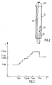
- FIG 2 is shown the free end of stimulation of a probe 22 having a stimulation end 23.
- This is connected to one of the terminals 10, 11, via a spiral conductive wire 24 , the assembly being placed in a sheath 24a.
- the other terminal 10, 11 can be connected to another electrode, for example the mass pacemaker housing.
- On the external surface of the sheath 24a is placed a thermistor 25 forming an integral part of the probe 22.
- This thermistor 25 is placed, in such a way that it allows an effective measurement of the body which surrounds it, for example the blood of the heart. of the patient.
- To this thermistor 25 are connected conductors 26 also embedded in the sheath 24a, connected to terminals 15 and 16 ( Figure 1).
- the thermistor 25 is moved away from the stimulation end 23, for example by a distance of the order of 10 cm, which allows a correct measurement of the temperature, the thermistor being placed in the right atrium near immediate delivery of the inferior vena cava.
- the resistance of the thermistor 25 varies according to the temperature of the medium which surrounds it. This causes a variation in the input current of the converter 17 which causes a corresponding variation in the frequency of the output signal of the converter 17.
- the microprocessor 1 samples the temperature by activating the counter 19, via the control line 21 for a predetermined period. . The reading at the output of the counter 19 is transferred to the microprocessor 1 via the bus 20 and the bus 4. The microprocessor 1 adjusts the output frequency for the stimulation amplifier 9 via the line 8, according to the value read from counter 19 and the preprogrammed stimulation frequencies found in memory 2.
- FIG. 3 is a diagram giving the temperature of the blood T on the abscissa - corresponding to the patient's level of physical activity - measured by thermistor 25, and on the ordinate, the stimulation frequency F.
- a temperature Thorm which is a temperature considered normal for the patient, corresponds a stimulation frequency Fnorm. If the patient's temperature increases from Tnorm, due in particular to physical activity, the stimulation frequency will also increase and this up to a maximum frequency Fmax corresponding to a temperature Tmax. In the same way, if the blood temperature decreases, from the temperature Tnorm, the stimulation frequency decreases and this up to a minimum stimulation frequency Fmin corresponding to a temperature Tmin.
- the frequency will remain unchanged at the value Fmin.
- the frequency will remain unchanged at the Fmax value until the temperature reaches a Tlim limit.
- the stimulation frequency is reduced to a value less than Fmax, that is to say Finf which is, for example, of the order of 20% less than the frequency Fmax.
- Tlim can for example be chosen between 38 ° C and 39 ° C, preferably equal to or close to 38.5 ° C (Tnorm being equal to or of the order of 37 ° C).
- the frequency Finf can be, for example, 15 to 25% lower than the frequency Fmax.
- the function linking frequency to temperature can be programmed.
- this function is illustrated, in its central part, by a staircase, that is to say that the frequency remains constant in the temperature range and jumps when the temperature reaches the limit of the beach.
- a staircase that is to say that the frequency remains constant in the temperature range and jumps when the temperature reaches the limit of the beach.
- rays can be provided which are capable of averaging the temperature or even of smoothing the temperature variation curve.
Landscapes
- Health & Medical Sciences (AREA)
- Heart & Thoracic Surgery (AREA)
- Cardiology (AREA)
- Life Sciences & Earth Sciences (AREA)
- Engineering & Computer Science (AREA)
- Hematology (AREA)
- Nuclear Medicine, Radiotherapy & Molecular Imaging (AREA)
- Radiology & Medical Imaging (AREA)
- Biomedical Technology (AREA)
- Animal Behavior & Ethology (AREA)
- General Health & Medical Sciences (AREA)
- Public Health (AREA)
- Veterinary Medicine (AREA)
- Vascular Medicine (AREA)
- Biophysics (AREA)
- Physiology (AREA)
- Electrotherapy Devices (AREA)
- Materials For Medical Uses (AREA)
Applications Claiming Priority (2)
| Application Number | Priority Date | Filing Date | Title |
|---|---|---|---|
| FR8312740 | 1983-08-02 | ||
| FR8312740A FR2550095B1 (fr) | 1983-08-02 | 1983-08-02 | Procede de commande d'un stimulateur cardiaque et sonde pour la mise en oeuvre du procede |
Related Parent Applications (2)
| Application Number | Title | Priority Date | Filing Date |
|---|---|---|---|
| EP84401536A Division EP0133828B1 (de) | 1983-08-02 | 1984-07-20 | Verfahren zum Steuern eines Herzschrittmachers |
| EP84401536.2 Division | 1984-07-20 |
Publications (2)
| Publication Number | Publication Date |
|---|---|
| EP0400157A2 true EP0400157A2 (de) | 1990-12-05 |
| EP0400157A3 EP0400157A3 (de) | 1991-02-27 |
Family
ID=9291338
Family Applications (2)
| Application Number | Title | Priority Date | Filing Date |
|---|---|---|---|
| EP84401536A Expired - Lifetime EP0133828B1 (de) | 1983-08-02 | 1984-07-20 | Verfahren zum Steuern eines Herzschrittmachers |
| EP19880100834 Withdrawn EP0400157A3 (de) | 1983-08-02 | 1984-07-20 | Herzschrittmachersonde |
Family Applications Before (1)
| Application Number | Title | Priority Date | Filing Date |
|---|---|---|---|
| EP84401536A Expired - Lifetime EP0133828B1 (de) | 1983-08-02 | 1984-07-20 | Verfahren zum Steuern eines Herzschrittmachers |
Country Status (4)
| Country | Link |
|---|---|
| EP (2) | EP0133828B1 (de) |
| AT (1) | ATE50509T1 (de) |
| DE (1) | DE3481405D1 (de) |
| FR (1) | FR2550095B1 (de) |
Cited By (2)
| Publication number | Priority date | Publication date | Assignee | Title |
|---|---|---|---|---|
| US6190378B1 (en) | 1997-12-05 | 2001-02-20 | Massachusetts Institute Of Technology | Cryosurgical instrument and related techniques |
| US11021259B1 (en) | 2021-01-07 | 2021-06-01 | Philip Onni Jarvinen | Aircraft exhaust mitigation system and process |
Families Citing this family (13)
| Publication number | Priority date | Publication date | Assignee | Title |
|---|---|---|---|---|
| DE3419439C1 (de) * | 1984-05-24 | 1985-11-21 | Eckhard Dr. 8000 München Alt | Belastungsabhaengig frequenzvariabler Herzschrittmacher |
| DE3422913A1 (de) * | 1984-06-20 | 1986-01-02 | Siemens AG, 1000 Berlin und 8000 München | Regelschaltung zur anpassung der stimulationsfrequenz eines herzschrittmachers an die belastung eines patienten |
| DE3689347D1 (de) * | 1985-09-17 | 1994-01-13 | Biotronik Mess & Therapieg | Herzschrittmacher. |
| EP0225839B1 (de) * | 1985-09-17 | 1993-12-01 | BIOTRONIK Mess- und Therapiegeräte GmbH & Co Ingenieurbüro Berlin | Herzschrittmacher |
| DE3650261D1 (de) * | 1985-09-17 | 1995-04-13 | Biotronik Mess & Therapieg | Herzschrittmacher. |
| DE3541598A1 (de) * | 1985-11-25 | 1987-11-19 | Alt Eckhard | Belastungsabhaengig frequenzvariabler herzschrittmacher |
| US4803987A (en) * | 1986-06-11 | 1989-02-14 | Intermedics, Inc. | Temperature responsive controller for cardiac pacer |
| EP0249822B1 (de) * | 1986-06-16 | 1991-10-16 | Siemens Aktiengesellschaft | Frequenzgesteuerter Herzschrittmacher |
| EP0256437B1 (de) * | 1986-08-18 | 1991-09-04 | Siemens Aktiengesellschaft | Messvorrichtung zur Steuerung implantierbarer Körperersatzteile |
| FR2604908B1 (fr) * | 1986-10-13 | 1990-06-22 | Saint Nicolas Cie Financiere | Procede de reglage d'un stimulateur cardiaque implantable en fonction de l'effort du patient porteur du stimulateur, stimulateur cardiaque implantable a parametres reglables et programmateur externe de commande d'un stimulateur cardiaque implantable reglable |
| SE8702523D0 (sv) * | 1987-06-17 | 1987-06-17 | Siemens Elema Ab | Rate responsive pacemaker |
| US4984572A (en) * | 1988-08-18 | 1991-01-15 | Leonard Bloom | Hemodynamically responsive system for and method of treating a malfunctioning heart |
| DE58907517D1 (de) * | 1989-02-10 | 1994-05-26 | Siemens Ag | Implantierbarer Herzschrittmacher und Verfahren zum Betreiben eines Herzschrittmachers mit auf einen Maximalwert begrenzter Folgefrequenz der Stimulationen von Herzmuskelkontraktionen. |
Family Cites Families (7)
| Publication number | Priority date | Publication date | Assignee | Title |
|---|---|---|---|---|
| US3867950A (en) * | 1971-06-18 | 1975-02-25 | Univ Johns Hopkins | Fixed rate rechargeable cardiac pacemaker |
| FR2305720A1 (fr) * | 1975-03-26 | 1976-10-22 | Gouault Jean | Appareil de releve de temperatures superficielles, notamment cutanees |
| US3996928A (en) * | 1975-05-28 | 1976-12-14 | Marx Alvin J | Patient vital-signs automated measuring apparatus |
| DE2609365A1 (de) * | 1976-03-06 | 1977-09-08 | Georg Dr Med Csapo | Elektrischer herzschrittmacher |
| US4467807A (en) * | 1981-11-23 | 1984-08-28 | Medtronic, Inc. | Rate adaptive demand pacemaker |
| US4436092A (en) * | 1982-05-19 | 1984-03-13 | Purdue Research Foundation | Exercise responsive cardiac pacemaker |
| DE3419439C1 (de) * | 1984-05-24 | 1985-11-21 | Eckhard Dr. 8000 München Alt | Belastungsabhaengig frequenzvariabler Herzschrittmacher |
-
1983
- 1983-08-02 FR FR8312740A patent/FR2550095B1/fr not_active Expired
-
1984
- 1984-07-20 DE DE8484401536T patent/DE3481405D1/de not_active Expired - Lifetime
- 1984-07-20 EP EP84401536A patent/EP0133828B1/de not_active Expired - Lifetime
- 1984-07-20 AT AT84401536T patent/ATE50509T1/de not_active IP Right Cessation
- 1984-07-20 EP EP19880100834 patent/EP0400157A3/de not_active Withdrawn
Cited By (2)
| Publication number | Priority date | Publication date | Assignee | Title |
|---|---|---|---|---|
| US6190378B1 (en) | 1997-12-05 | 2001-02-20 | Massachusetts Institute Of Technology | Cryosurgical instrument and related techniques |
| US11021259B1 (en) | 2021-01-07 | 2021-06-01 | Philip Onni Jarvinen | Aircraft exhaust mitigation system and process |
Also Published As
| Publication number | Publication date |
|---|---|
| FR2550095B1 (fr) | 1986-09-26 |
| DE3481405D1 (de) | 1990-04-05 |
| EP0133828A1 (de) | 1985-03-06 |
| FR2550095A1 (fr) | 1985-02-08 |
| ATE50509T1 (de) | 1990-03-15 |
| EP0133828B1 (de) | 1990-02-28 |
| EP0400157A3 (de) | 1991-02-27 |
Similar Documents
| Publication | Publication Date | Title |
|---|---|---|
| EP0133828B1 (de) | Verfahren zum Steuern eines Herzschrittmachers | |
| EP0663219B1 (de) | Aktive implantierbare Vorrichtung | |
| US5598847A (en) | Implantable flow sensor apparatus and method | |
| EP1107009A1 (de) | Gerät zur Messung der Stromintensität in einer Leitung | |
| FR2512229A1 (fr) | Transducteur multiplexe a deux conducteurs implantable dans le corps | |
| FR2604629A1 (fr) | Stimulateur cardiaque a commande automatique de sensibilite | |
| FR2792405A1 (fr) | Debimetre electromagnetique | |
| FR2533705A1 (fr) | Detecteur de concentration ionique dans un liquide | |
| JPS6311171A (ja) | 心臓ペ−スメ−カ− | |
| CA2030684A1 (fr) | Sonde de pace-maker a pole de stimulation auxiliaire | |
| EP3074717B1 (de) | Elektronischer zünder | |
| EP0320351A1 (de) | Herzschrittmacher und sein Einstellverfahren | |
| EP0544589A1 (de) | Gerät zur Messung des realen Lastfaktors eines elektrischen Generators | |
| GB2107116B (en) | Temperature sensing device with high resistance connecting leads | |
| EP1959860B1 (de) | Zubehör für ein apex-lokalisationsgerät | |
| FR2723235A1 (fr) | Dispositifs de detection d'incendie comportant un capteur de correction | |
| FR2738473A1 (fr) | Dispositif d'electro-physiologie | |
| US4029959A (en) | Plant light sensor adaptor | |
| EP1476725A2 (de) | Eingabemodul fur physikalische grösse | |
| CN113924038A (zh) | 用于可植入装置的温度感测架构 | |
| EP0475832B1 (de) | Elektronische Messschaltung mit einer gesteuerten elektrischen Versorgung für eine Widerstandssonde | |
| FR2518743A1 (fr) | Balance electrique a equilibrage electromagnetique de forces | |
| FR2532759A1 (fr) | Dispositif de mesure a pont de wheatstone | |
| FR2646907A1 (fr) | Dispositif de mesure de niveau et/ou de volume de liquide dans un reservoir | |
| BE854483A (fr) | Sonde thermometrique et son utilisation |
Legal Events
| Date | Code | Title | Description |
|---|---|---|---|
| PUAI | Public reference made under article 153(3) epc to a published international application that has entered the european phase |
Free format text: ORIGINAL CODE: 0009012 |
|
| AC | Divisional application: reference to earlier application |
Ref document number: 133828 Country of ref document: EP |
|
| AK | Designated contracting states |
Kind code of ref document: A2 Designated state(s): AT BE CH DE GB IT LI LU NL SE |
|
| PUAL | Search report despatched |
Free format text: ORIGINAL CODE: 0009013 |
|
| RIN1 | Information on inventor provided before grant (corrected) |
Inventor name: BREHIER, JACQUES |
|
| AK | Designated contracting states |
Kind code of ref document: A3 Designated state(s): AT BE CH DE GB IT LI LU NL SE |
|
| STAA | Information on the status of an ep patent application or granted ep patent |
Free format text: STATUS: THE APPLICATION IS DEEMED TO BE WITHDRAWN |
|
| 18D | Application deemed to be withdrawn |
Effective date: 19910828 |