EP0400256A1 - Dispositif de fermeture à coulisse pour poches de coulée et récipients similaires - Google Patents
Dispositif de fermeture à coulisse pour poches de coulée et récipients similaires Download PDFInfo
- Publication number
- EP0400256A1 EP0400256A1 EP89830242A EP89830242A EP0400256A1 EP 0400256 A1 EP0400256 A1 EP 0400256A1 EP 89830242 A EP89830242 A EP 89830242A EP 89830242 A EP89830242 A EP 89830242A EP 0400256 A1 EP0400256 A1 EP 0400256A1
- Authority
- EP
- European Patent Office
- Prior art keywords
- frame
- fixed
- slide
- springs
- appliance according
- Prior art date
- Legal status (The legal status is an assumption and is not a legal conclusion. Google has not performed a legal analysis and makes no representation as to the accuracy of the status listed.)
- Granted
Links
- 239000002184 metal Substances 0.000 claims abstract description 37
- 239000007787 solid Substances 0.000 claims abstract description 4
- 230000000295 complement effect Effects 0.000 claims 1
- 230000003245 working effect Effects 0.000 claims 1
- 230000006835 compression Effects 0.000 description 9
- 238000007906 compression Methods 0.000 description 9
- 239000011819 refractory material Substances 0.000 description 6
- 239000004570 mortar (masonry) Substances 0.000 description 3
- 238000007789 sealing Methods 0.000 description 2
- 229910000831 Steel Inorganic materials 0.000 description 1
- 239000011449 brick Substances 0.000 description 1
- 238000001816 cooling Methods 0.000 description 1
- 230000000875 corresponding effect Effects 0.000 description 1
- 238000007373 indentation Methods 0.000 description 1
- 239000007788 liquid Substances 0.000 description 1
- 229910001338 liquidmetal Inorganic materials 0.000 description 1
- 238000012423 maintenance Methods 0.000 description 1
- 230000000704 physical effect Effects 0.000 description 1
- 238000007747 plating Methods 0.000 description 1
- 229920000136 polysorbate Polymers 0.000 description 1
- 230000002028 premature Effects 0.000 description 1
- 238000011084 recovery Methods 0.000 description 1
- 230000000284 resting effect Effects 0.000 description 1
- 239000010959 steel Substances 0.000 description 1
Images


Classifications
-
- B—PERFORMING OPERATIONS; TRANSPORTING
- B22—CASTING; POWDER METALLURGY
- B22D—CASTING OF METALS; CASTING OF OTHER SUBSTANCES BY THE SAME PROCESSES OR DEVICES
- B22D41/00—Casting melt-holding vessels, e.g. ladles, tundishes, cups or the like
- B22D41/14—Closures
- B22D41/22—Closures sliding-gate type, i.e. having a fixed plate and a movable plate in sliding contact with each other for selective registry of their openings
- B22D41/24—Closures sliding-gate type, i.e. having a fixed plate and a movable plate in sliding contact with each other for selective registry of their openings characterised by a rectilinearly movable plate
-
- B—PERFORMING OPERATIONS; TRANSPORTING
- B22—CASTING; POWDER METALLURGY
- B22D—CASTING OF METALS; CASTING OF OTHER SUBSTANCES BY THE SAME PROCESSES OR DEVICES
- B22D41/00—Casting melt-holding vessels, e.g. ladles, tundishes, cups or the like
- B22D41/14—Closures
- B22D41/22—Closures sliding-gate type, i.e. having a fixed plate and a movable plate in sliding contact with each other for selective registry of their openings
- B22D41/40—Means for pressing the plates together
Definitions
- Slide-gate pouring appliances of the known type have a pair of holed plates made of refractory material, of which one fixed and one mobile, so that the relative movement of said plates allows the pouring appliance to be brought from a closed to an open position and vice versa.
- the fixed holed plate is secured to the bottom of the ladle by means of a fixed metal frame.
- the mobile holed plate is inserted in a metal frame which slides on a second metal frame, removable and tilting, which, in its working position, is pushed against the bottom of the ladle to as to keep the two opposite surfaces of the two fixed and mobile refractory plates in contact.
- sliding guides between the sliding frame also known as the third frame, and the removable frame.
- the removable frame also called the second frame
- some adjustable tightening means capable of accomplishing the following contrasting needs: - ensuring sealing of the two refractory surfaces in contact with one another; - allowing relative sliding during the slide-gate opening and closing movements.
- the removable frame was secured to the fixed frame with a clearance and subsequently the correct compression between the mobile plate and the fixed plate was achieved by suitable wedge-shaped means sliding longitudinally or along arcs of a circle.
- the required compression between the mobile and the fixed plates was achieved by means of torsion bars of a suitable length to allow recovery of the clearances and elastic application of a constant load all round the boundary of the removable frame by means of suitable squares protruding radially from these torsion bars.
- the known state of the art envisages, furthermore, in addition to said torsion bars invented by the applicant, the use of spring-operated means to be dynamic compressed during the phase of tightening the fixed and mobile refractory plates between said upper fixed and lower removable frames.
- the use of spring-operated means does entail some difficulties due to the fact that the pressure must be evenly applied to the whole surface of contact between the fixed and mobile refractory plates, in any relative position.
- a uniformly distributed pressure moreover, requires a uniform state of compression of these spring-operated means and this is not easy to achieve due to the large number of springs involved.
- An equal state of compression of the various springs calls for an equal distance between the shouldering surface of the springs themselves, which entails considerable difficulties considering that one of the linear dimensions on which said distance depends is the thickness of the refractory plates.
- the problem is further complicated by the fact that the characteristics of the springs in question change considerably with temperature and therefore in order to achieve an evenly distributed pressure over the surfaces of contact of the refractory plates, the springs involved must be maintained at the same temperature or at very similar temperatures to one another.
- the known state of the art envisages, for example, the use of a ring of springs around the hole in the sliding refractory plate, so as to bring the springs near to the annular area of the plate in which sealing must absolutely be accomplished: on the other hand, the closeness of the springs allows if not a uniform temperature, at least a reciprocal cooperation of the various springs, since the areas of influence of these springs overlap one another.
- the means for tightening the fixed plate against the mobile plate call for the compression of elastic means; however this compression is exerted by means of a dynamic action on lever-operated means, so that the effort on the part of the operator, however intense it may be, is limited in time: acting dynamically, the maximum intensity of the load applied can be greater, if it is applied only for a few fractions of a second. It is therefore possible to make even very large slide-gate pouring appliances.
- the elastic means are mounted in two parallel rows on horizontally pivoted metal supports which act on the sides of the removable frame and moreover they are constrained to the fixed frame.
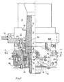
- 10 is the bottom plating of a ladle fitted with an opening into which a flattening ring 11 is inserted and welded.
- an annular firebrick 12 is inserted from above, fitted with a centering spigot 13 and at the top with an undercut 14 for the lower spigot of a second annular refractory brick 15.
- the set of two firebricks 12 and 15 forms the so-called pouring appliance holder, surrounded by the refractory lining of the ladle not illustrated in the drawing.
- the pouring-appliance holder 12-15 has a truncated cone shaped hole flared downwards in which a refractory sleeve 16 is housed, indicated hereinafter as the fixed upper refractory sleeve, and it is also commonly called the "internal pouring appliance”.
- the fixed upper sleeve 16 rests on top of a fixed refractory plate 17, holed, supported by a fixed metal frame 20, fixed by screws 21 to the underside of the flattening ring 11.
- the through holes for these screws 21 are indicated by 121.
- the refractory sleeve 16 and the refractory plate 17 are equipped with aligned holes 18 and 19 through which the liquid metal passes.
- the frame 20 has a wide circular opening 22 (see figure 4), through which the lower end of the sleeve 17 passes.
- centering ring 23 Inside the opening 22 in the fixed frame 20 there is a centering ring 23 equipped with radial lugs 24 suitable for securing by screws to special cavities 25 made in the inside surface of the fixed metal frame 20.
- the purpose of said centering ring 23 (see figures 1, 9 and 10) is to centre the lower end of the sleeve 16. It is equipped in two or more positions with flared indentations 25 which make it easier to insert a demolishing tool when the sleeve 16 has to be replaced due to wear.
- the fixed frame 20 has a wide longitudinal groove 26 with a ridged bottom, defined by longitudinal sides 27 within which the fixed refractory plate 17 is accommodated.
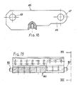
- longitudinal sides 27 there are two pairs of recesses 28 capable of housing the ends of two bridges 29 for retaining the refractory plate 17 longitudinally (see figures 7 and 8).
- Figure 11 shows one of these bridges, secured to the fixed frame 20 by means of screws 123 which pass through holes 124 in the bridge and screw into threaded holes 125 in the frame 20; the same figure also shows the centering ring 23 in an assembled position.
- the underside of the fixed metal frame 20 is equipped with longitudinal grooves 122 capable of accommodating mortar for fixing the fixed refractory plate 17.
- longitudinal grooves 122 capable of accommodating mortar for fixing the fixed refractory plate 17.
- the vertical brackets 40 are fitted with a centering spigot 42 which corresponds to the bottom of the recesses 128.
- the vertical brackets 40 are secured to the fixed metal frame 20 by means of screws.
- the vertical brackets 40 are also fitted with a pair of horizontal holes parallel to the longitudinal direction of the metal frame 20.
- the first of these holes is aligned with the hole 127 in the adjacent lug 126 and is capable of accommodating together with the latter a pin 44 (see figure 2).
- the upper end 46 of a link rod 45 (see figure 18), equipped with an upper hole 47 for this purpose, is jointed to the pin 44, between the vertical bracket 40 and the lug 126.
- this link rod 45 On its lower end this link rod 45 has a second hole 48, also called the link rod lower hole.
- the function of the link rod (45) is explained later; for the moment it is sufficient to say that the four lugs 126, the four vertical brackets 40 and the four pins 44 support four symmetrically arranged link rods 45.
- This second hole 49 is capable of accommodating a pin 50 (see figure 2) which at the other end passes through a vertically elongated slot 32 prepared in a lug 31 protruding sideways from the removable frame 30.
- the second frame 30, also called the removable frame is supported by four pins 50 protruding from the lower hole 49 of the brackets 40, through the slots 32 in the lugs 31. Since these slots are elongated vertically, when the removable metal frame 30 is hanging from the pins 50 it is vertically mobile for a distance equal to the difference between the length of these slots and the diameter of the pin 50.
- the removable frame 30 can be tilted on a vertical axis for the necessary maintenance operations.
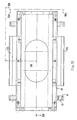
- the same removable frame 30 has a second pair of lower longitudinal flanges, that is to say located at a level lower than the first two, protruding inwards.
- the removable frame 30 has a wide central opening, elongated, indicated by 35 (see fig. 15).
- Two gibs 36 rest on the upper surface of the internal flanges 34 (see fig.
- the gibs 61 are housed in longitudinal steps 62 prepared in the lower side edges of the sliding frame 60.
- the threaded holes 63 for housing the retaining screws 132 (figure 1) can be seen in figures 23 to 25.
- the sliding frame 60 has a central through hole 64 and, on its upper surface, an elongated impression 65 capable of accomodating a refractory plate 66 equipped with a central hole 67. Suitable grooves 68 accommodate the mortar for securing the refractory plate 66 which slides on the metal frame 60.
- On the two ends of the sliding frame 60 there are holes 69 for fixing a rod to control the longitudinal position of the sliding frame.
- small guide plates 133 are fixed by means of screws 134 to the upper surface of the removable frame 30; the inner surface of these plates skims the sides of the sliding metal frame 60, ensuring the required relative movement in a straight line.
- the central hole 64 in the metal frame 60 is passed through by a slender metal sleeve 70 (see figures 26 and 27) fitted with holed lugs which protrude radially outwards 73 and 72, located on two levels; the upper lugs, 73, are applied to the lower surface of the sliding metal frame 60 by means of screws 73 which screw into threaded holes 74; the lower lugs support a first metal plate 75 which acts as a heat shield, and which is obviously mobile in respect of the sliding frame 60, by means of screws 76.
- the inner surface of the metal sleeve 70 is tapered inwards and downwards so as to provide a conical resting surface for the corresponding outer surface of a second refractory sleeve 77 or, as in the case shown in the figure, for the outer surface of its metal casing.
- the upper edge of the sleeve 77 rests against the bottom surface of the sliding refractory plate 66 by means of a suitable key.
- the fixed frame 20 is secured to the lower surface of the flattening ring 11 by means of the screws 21.
- the fixed refractory plate 17 is supported against the lower surface of the metal frame 20 by means of a thin layer of refractory mortar and by means of retaining bridges 29.
- the vertical brackets 40 protruding downwards from the sides of the fixed frame 20 in turn support the removable frame 30 by means of pins 50 which pass through the slots 32.
- the removable metal frame 30 supports the sliding frame 60 and the upper refractory plate 66 above it by the pairs of gibs 61 and 36.
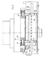
- a series of packs of springs 87 preferably cup springs, mounted on parallel vertical pins 88 protruding downwards from an elongated prod 89 is inserted into the groove 86 defined by the solid bottom 81 and by the sides 82.
- the elongated prod 89 is fitted with side flanges 90 which hit against the lower surfaces of the inner flanges 83 of the casing 80, due to the action of the springs 87.
- a transverse pin 91, mobile with clearance in a suitable pair of vertically slotted cavities in the sides of the casing 80 ensures axial locking of the prod 89 in the groove 86.
- Two pins 92 suitable for being housed in the lower holes 48 of the link rods 45 protrude from the two ends of the casing 80; the two casings 80 can therefore oscillate around the axis of said pins.
- the upper outer flanges 33 of the removable frame 30 are fitted with a very open V shaped groove 135 in which the end of the elongated prod 89 will fit.
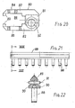
- the position of the link rods 45 and of the casings for the springs 80 when the removable frame 30 comes to rest on the pins 50 by means of the slots 32 in the lugs 31 is schematically illustrated in figure 28.
- the axis of the link rods 45 is external to that of the casing 80 and above all it is external to the line of application of the prod 89 on the throat of the lower V shaped groove, 135, on the underside of the upper outer flanges 33 of the removable metal frame 30.
- the springs will undergo a maximum compression after which, if rotation is continued through a suitable angle, however small, the springs will extend partially after the axis of the link rod 45 has passed the line of application of the prod 89, as shown schematically in figure 29.
- the removable frame 30 will thus be pressed elastically against the fixed frame 20 as shown in figure 1 : in particular the mobile refractory plate will be pressed against the fixed refractory plate.
Landscapes
- Engineering & Computer Science (AREA)
- Mechanical Engineering (AREA)
- Casting Support Devices, Ladles, And Melt Control Thereby (AREA)
- Seal Device For Vehicle (AREA)
- Cable Accessories (AREA)
- Bag Frames (AREA)
- Load-Engaging Elements For Cranes (AREA)
- Shovels (AREA)
- Chair Legs, Seat Parts, And Backrests (AREA)
- Treatment Of Steel In Its Molten State (AREA)
Priority Applications (8)
| Application Number | Priority Date | Filing Date | Title |
|---|---|---|---|
| AT89830242T ATE98918T1 (de) | 1989-06-02 | 1989-06-02 | Schieberverschluss fuer giesspfannen und aehnliche vorrichtungen. |
| DE198989830242T DE400256T1 (de) | 1989-06-02 | 1989-06-02 | Schieberverschluss fuer giesspfannen und aehnliche vorrichtungen. |
| ES89830242T ES2020155A4 (es) | 1989-06-02 | 1989-06-02 | Herramienta de vertido con puerta deslizable para cucharones y dispositivos similares. |
| DE89830242T DE68911675T2 (de) | 1989-06-02 | 1989-06-02 | Schieberverschluss für Giesspfannen und ähnliche Vorrichtungen. |
| EP89830242A EP0400256B1 (fr) | 1989-06-02 | 1989-06-02 | Dispositif de fermeture à coulisse pour poches de coulée et récipients similaires |
| CA000602138A CA1317455C (fr) | 1989-06-02 | 1989-06-08 | Obturateur a guillotine pour poche de coulee ou installations analogues |
| US07/363,857 US4953760A (en) | 1989-06-02 | 1989-06-09 | Slide-gate pouring appliance for ladles and similar devices |
| GR91300050T GR910300050T1 (en) | 1989-06-02 | 1991-11-15 | Slide-gate pouring appliance for ladles and similar devices |
Applications Claiming Priority (1)
| Application Number | Priority Date | Filing Date | Title |
|---|---|---|---|
| EP89830242A EP0400256B1 (fr) | 1989-06-02 | 1989-06-02 | Dispositif de fermeture à coulisse pour poches de coulée et récipients similaires |
Publications (2)
| Publication Number | Publication Date |
|---|---|
| EP0400256A1 true EP0400256A1 (fr) | 1990-12-05 |
| EP0400256B1 EP0400256B1 (fr) | 1993-12-22 |
Family
ID=8203222
Family Applications (1)
| Application Number | Title | Priority Date | Filing Date |
|---|---|---|---|
| EP89830242A Expired - Lifetime EP0400256B1 (fr) | 1989-06-02 | 1989-06-02 | Dispositif de fermeture à coulisse pour poches de coulée et récipients similaires |
Country Status (7)
| Country | Link |
|---|---|
| US (1) | US4953760A (fr) |
| EP (1) | EP0400256B1 (fr) |
| AT (1) | ATE98918T1 (fr) |
| CA (1) | CA1317455C (fr) |
| DE (2) | DE400256T1 (fr) |
| ES (1) | ES2020155A4 (fr) |
| GR (1) | GR910300050T1 (fr) |
Cited By (3)
| Publication number | Priority date | Publication date | Assignee | Title |
|---|---|---|---|---|
| EP0445087A3 (en) * | 1990-03-02 | 1992-04-29 | Nuova Sanac S.P.A. | Box nozzle for ladles and the like, with lateral pressure springs |
| DE10033904A1 (de) * | 2000-07-12 | 2002-01-31 | Stopinc Ag Huenenberg | Schieberverschluss zum Vergiessen von Metallschmelze, sowie eine dazugehörige feuerfeste Platteneinheit |
| CN110526099A (zh) * | 2019-09-27 | 2019-12-03 | 中船动力有限公司 | 船用柴油机的前端箱安装起吊工装 |
Families Citing this family (6)
| Publication number | Priority date | Publication date | Assignee | Title |
|---|---|---|---|---|
| JP3021333B2 (ja) * | 1995-10-31 | 2000-03-15 | 黒崎窯業株式会社 | スライディングノズル装置と同装置を用いる面圧負荷解除方法 |
| RU2147971C1 (ru) * | 1999-01-25 | 2000-04-27 | Алпатов Анатолий Александрович | Шиберный затвор литейного ковша |
| US6238316B1 (en) | 1999-04-23 | 2001-05-29 | Gary Lee Sturm | Differential axle speed sensing mechanism |
| CN102310171A (zh) * | 2011-03-09 | 2012-01-11 | 维苏威高级陶瓷(苏州)有限公司 | 中间包可拆卸控流机构 |
| CN105887004B (zh) * | 2016-06-04 | 2019-03-22 | 芜湖市智行天下工业设计有限公司 | 一种便于金属件充分接触锌粉的渗锌炉 |
| US11331719B2 (en) * | 2020-02-28 | 2022-05-17 | Knöllinger FLO-TEC GmbH | Slide gate with compensation device for the contact pressure |
Citations (1)
| Publication number | Priority date | Publication date | Assignee | Title |
|---|---|---|---|---|
| GB2158380A (en) * | 1984-05-11 | 1985-11-13 | Flogates Ltd | Mounting equipment e.g. valve, to molten metal vessel |
Family Cites Families (5)
| Publication number | Priority date | Publication date | Assignee | Title |
|---|---|---|---|---|
| US4063668A (en) * | 1971-06-07 | 1977-12-20 | United States Steel Corporation | Ladle gate valve |
| US3765579A (en) * | 1972-05-10 | 1973-10-16 | United States Steel Corp | Linearly movable gate mechanism |
| CH653933A5 (de) * | 1981-05-19 | 1986-01-31 | Stopinc Ag | Schiebeverschluss fuer schmelzegefaesse. |
| US4667937A (en) * | 1983-03-24 | 1987-05-26 | Flo-Con Systems, Inc. | Heat shield for sliding gate valve |
| JPH0335481Y2 (fr) * | 1984-09-11 | 1991-07-26 |
-
1989
- 1989-06-02 AT AT89830242T patent/ATE98918T1/de not_active IP Right Cessation
- 1989-06-02 ES ES89830242T patent/ES2020155A4/es active Pending
- 1989-06-02 DE DE198989830242T patent/DE400256T1/de active Pending
- 1989-06-02 EP EP89830242A patent/EP0400256B1/fr not_active Expired - Lifetime
- 1989-06-02 DE DE89830242T patent/DE68911675T2/de not_active Expired - Fee Related
- 1989-06-08 CA CA000602138A patent/CA1317455C/fr not_active Expired - Fee Related
- 1989-06-09 US US07/363,857 patent/US4953760A/en not_active Expired - Lifetime
-
1991
- 1991-11-15 GR GR91300050T patent/GR910300050T1/el unknown
Patent Citations (1)
| Publication number | Priority date | Publication date | Assignee | Title |
|---|---|---|---|---|
| GB2158380A (en) * | 1984-05-11 | 1985-11-13 | Flogates Ltd | Mounting equipment e.g. valve, to molten metal vessel |
Non-Patent Citations (2)
| Title |
|---|
| PATENT ABSTRACTS OF JAPAN, vol. 11, no. 14 (M-553)[2461], 14th January 1987; & JP-A-61 189 868 (TCK KK) 23-08-1986 * |
| PATENT ABSTRACTS OF JAPAN, vol. 12, no. 160 (M-697)[3007], 14th May 1988; & JP-A-62 279 071 (KUROSAKI REFRACT CO. LTD) 03-12-1987 * |
Cited By (4)
| Publication number | Priority date | Publication date | Assignee | Title |
|---|---|---|---|---|
| EP0445087A3 (en) * | 1990-03-02 | 1992-04-29 | Nuova Sanac S.P.A. | Box nozzle for ladles and the like, with lateral pressure springs |
| DE10033904A1 (de) * | 2000-07-12 | 2002-01-31 | Stopinc Ag Huenenberg | Schieberverschluss zum Vergiessen von Metallschmelze, sowie eine dazugehörige feuerfeste Platteneinheit |
| CN110526099A (zh) * | 2019-09-27 | 2019-12-03 | 中船动力有限公司 | 船用柴油机的前端箱安装起吊工装 |
| CN110526099B (zh) * | 2019-09-27 | 2024-04-05 | 中船动力有限公司 | 船用柴油机的前端箱安装起吊工装 |
Also Published As
| Publication number | Publication date |
|---|---|
| DE400256T1 (de) | 1991-05-23 |
| ATE98918T1 (de) | 1994-01-15 |
| GR910300050T1 (en) | 1991-11-15 |
| DE68911675D1 (de) | 1994-02-03 |
| CA1317455C (fr) | 1993-05-11 |
| EP0400256B1 (fr) | 1993-12-22 |
| DE68911675T2 (de) | 1994-05-05 |
| ES2020155A4 (es) | 1991-08-01 |
| US4953760A (en) | 1990-09-04 |
Similar Documents
| Publication | Publication Date | Title |
|---|---|---|
| EP0400256A1 (fr) | Dispositif de fermeture à coulisse pour poches de coulée et récipients similaires | |
| US4480771A (en) | Rotary nozzle system for metallurgical vessels | |
| US4524956A (en) | Linear sliding closure unit | |
| CA1067672A (fr) | Appareil permettant de regler l'ecoulement de metal en fusion | |
| CA2123253A1 (fr) | Dispositif de centrage pour moufle de levage | |
| US5698129A (en) | Sliding gate valve for a metallurgical vessel | |
| GB2213412A (en) | Refractory valve plate for sliding gate valve | |
| US4577785A (en) | Hinged rotary nozzle | |
| US4294437A (en) | Slide closure for the pouring nozzle of a molten metal vessel | |
| US4687186A (en) | Gripping device for a wearing element | |
| US4191364A (en) | Support for metallurgical vessels | |
| US4875606A (en) | Refractory valve body and sliding closure unit incorporating the same | |
| US6019258A (en) | Plate change device for a metallurgical vessel and set of plates for this drawer | |
| KR20020086938A (ko) | 슬라이딩 게이트의 내화판 체결 장치 | |
| DE3423156C1 (de) | Schwenkschieber fuer den Ausguss metallurgischer Gefaesse | |
| RU2410443C2 (ru) | Опрокидываемая металлургическая емкость | |
| AU694651B2 (en) | Sliding gate valve | |
| JPS5841142B2 (ja) | 溶融金属の流れを制御する摺動ゲ−ト閉鎖機構 | |
| US4051589A (en) | Process and apparatus for the assembly of sliding gate valve units for casting ladles | |
| EP0590174B1 (fr) | Fermeture coulissante pour récipients de coulée pourvue de barres de torsion latérales | |
| EP0733423B1 (fr) | Système de coulée avec dispositif de fermeture coulissante pour la régulation du jet de coulée sortant d'un récipient de coulée | |
| AU720885C (en) | Plate change drawer for a metallurgical vessel and set of plates for this drawer | |
| GB2235889A (en) | Improvements in or relating to refractory monoblock stoppers | |
| GB2158380A (en) | Mounting equipment e.g. valve, to molten metal vessel | |
| RU2358833C1 (ru) | Шиберный затвор литейного ковша и устройство перевода каретки шиберного затвора в положение обслуживания |
Legal Events
| Date | Code | Title | Description |
|---|---|---|---|
| PUAI | Public reference made under article 153(3) epc to a published international application that has entered the european phase |
Free format text: ORIGINAL CODE: 0009012 |
|
| AK | Designated contracting states |
Kind code of ref document: A1 Designated state(s): AT BE CH DE ES FR GB GR LI LU NL SE |
|
| 17P | Request for examination filed |
Effective date: 19901205 |
|
| TCNL | Nl: translation of patent claims filed | ||
| TCAT | At: translation of patent claims filed | ||
| EL | Fr: translation of claims filed | ||
| DET | De: translation of patent claims | ||
| 17Q | First examination report despatched |
Effective date: 19920211 |
|
| GRAA | (expected) grant |
Free format text: ORIGINAL CODE: 0009210 |
|
| AK | Designated contracting states |
Kind code of ref document: B1 Designated state(s): AT BE CH DE ES FR GB GR LI LU NL SE |
|
| PG25 | Lapsed in a contracting state [announced via postgrant information from national office to epo] |
Ref country code: SE Effective date: 19931222 Ref country code: NL Effective date: 19931222 Ref country code: LI Effective date: 19931222 Ref country code: GR Free format text: LAPSE BECAUSE OF FAILURE TO SUBMIT A TRANSLATION OF THE DESCRIPTION OR TO PAY THE FEE WITHIN THE PRESCRIBED TIME-LIMIT Effective date: 19931222 Ref country code: CH Effective date: 19931222 Ref country code: BE Effective date: 19931222 Ref country code: AT Effective date: 19931222 |
|
| REF | Corresponds to: |
Ref document number: 98918 Country of ref document: AT Date of ref document: 19940115 Kind code of ref document: T |
|
| REF | Corresponds to: |
Ref document number: 68911675 Country of ref document: DE Date of ref document: 19940203 |
|
| ET | Fr: translation filed | ||
| REG | Reference to a national code |
Ref country code: CH Ref legal event code: PL |
|
| PG25 | Lapsed in a contracting state [announced via postgrant information from national office to epo] |
Ref country code: ES Free format text: LAPSE BECAUSE OF FAILURE TO SUBMIT A TRANSLATION OF THE DESCRIPTION OR TO PAY THE FEE WITHIN THE PRESCRIBED TIME-LIMIT Effective date: 19940402 |
|
| NLV1 | Nl: lapsed or annulled due to failure to fulfill the requirements of art. 29p and 29m of the patents act | ||
| PG25 | Lapsed in a contracting state [announced via postgrant information from national office to epo] |
Ref country code: LU Free format text: LAPSE BECAUSE OF NON-PAYMENT OF DUE FEES Effective date: 19940630 |
|
| PLBE | No opposition filed within time limit |
Free format text: ORIGINAL CODE: 0009261 |
|
| STAA | Information on the status of an ep patent application or granted ep patent |
Free format text: STATUS: NO OPPOSITION FILED WITHIN TIME LIMIT |
|
| 26N | No opposition filed | ||
| REG | Reference to a national code |
Ref country code: FR Ref legal event code: TP Ref country code: FR Ref legal event code: CD |
|
| REG | Reference to a national code |
Ref country code: GB Ref legal event code: 732E |
|
| PGFP | Annual fee paid to national office [announced via postgrant information from national office to epo] |
Ref country code: GB Payment date: 19980521 Year of fee payment: 10 |
|
| PGFP | Annual fee paid to national office [announced via postgrant information from national office to epo] |
Ref country code: DE Payment date: 19980528 Year of fee payment: 10 |
|
| PGFP | Annual fee paid to national office [announced via postgrant information from national office to epo] |
Ref country code: FR Payment date: 19980605 Year of fee payment: 10 |
|
| PG25 | Lapsed in a contracting state [announced via postgrant information from national office to epo] |
Ref country code: GB Free format text: LAPSE BECAUSE OF NON-PAYMENT OF DUE FEES Effective date: 19990602 |
|
| PG25 | Lapsed in a contracting state [announced via postgrant information from national office to epo] |
Ref country code: FR Free format text: THE PATENT HAS BEEN ANNULLED BY A DECISION OF A NATIONAL AUTHORITY Effective date: 19990630 |
|
| GBPC | Gb: european patent ceased through non-payment of renewal fee |
Effective date: 19990602 |
|
| PG25 | Lapsed in a contracting state [announced via postgrant information from national office to epo] |
Ref country code: DE Free format text: LAPSE BECAUSE OF NON-PAYMENT OF DUE FEES Effective date: 20000503 |
|
| REG | Reference to a national code |
Ref country code: FR Ref legal event code: ST |