EP0400257A1 - Dispositif de fermeture à coulisse, en matériau réfractaire, pour récipients métallurgiques - Google Patents
Dispositif de fermeture à coulisse, en matériau réfractaire, pour récipients métallurgiques Download PDFInfo
- Publication number
- EP0400257A1 EP0400257A1 EP89830243A EP89830243A EP0400257A1 EP 0400257 A1 EP0400257 A1 EP 0400257A1 EP 89830243 A EP89830243 A EP 89830243A EP 89830243 A EP89830243 A EP 89830243A EP 0400257 A1 EP0400257 A1 EP 0400257A1
- Authority
- EP
- European Patent Office
- Prior art keywords
- refractory
- pouring
- slide
- fact
- appliance
- Prior art date
- Legal status (The legal status is an assumption and is not a legal conclusion. Google has not performed a legal analysis and makes no representation as to the accuracy of the status listed.)
- Granted
Links
- 239000011819 refractory material Substances 0.000 title claims abstract description 13
- 239000002184 metal Substances 0.000 claims description 14
- 239000004570 mortar (masonry) Substances 0.000 claims description 6
- 230000013011 mating Effects 0.000 claims description 2
- 230000000284 resting effect Effects 0.000 claims 1
- 238000005266 casting Methods 0.000 abstract 1
- 230000000694 effects Effects 0.000 description 6
- 238000012423 maintenance Methods 0.000 description 6
- 229910000831 Steel Inorganic materials 0.000 description 5
- 239000010959 steel Substances 0.000 description 5
- 239000007788 liquid Substances 0.000 description 3
- 238000009826 distribution Methods 0.000 description 2
- 229910001338 liquidmetal Inorganic materials 0.000 description 2
- 239000011822 basic refractory Substances 0.000 description 1
- 239000011449 brick Substances 0.000 description 1
- 230000003247 decreasing effect Effects 0.000 description 1
- 238000003780 insertion Methods 0.000 description 1
- 230000037431 insertion Effects 0.000 description 1
- 238000004519 manufacturing process Methods 0.000 description 1
- 239000000463 material Substances 0.000 description 1
- 238000005259 measurement Methods 0.000 description 1
- 229920000136 polysorbate Polymers 0.000 description 1
- 238000007789 sealing Methods 0.000 description 1
- 239000000126 substance Substances 0.000 description 1
- 230000001131 transforming effect Effects 0.000 description 1
- 239000002699 waste material Substances 0.000 description 1
Images



Classifications
-
- B—PERFORMING OPERATIONS; TRANSPORTING
- B22—CASTING; POWDER METALLURGY
- B22D—CASTING OF METALS; CASTING OF OTHER SUBSTANCES BY THE SAME PROCESSES OR DEVICES
- B22D41/00—Casting melt-holding vessels, e.g. ladles, tundishes, cups or the like
- B22D41/14—Closures
- B22D41/22—Closures sliding-gate type, i.e. having a fixed plate and a movable plate in sliding contact with each other for selective registry of their openings
- B22D41/24—Closures sliding-gate type, i.e. having a fixed plate and a movable plate in sliding contact with each other for selective registry of their openings characterised by a rectilinearly movable plate
-
- B—PERFORMING OPERATIONS; TRANSPORTING
- B22—CASTING; POWDER METALLURGY
- B22D—CASTING OF METALS; CASTING OF OTHER SUBSTANCES BY THE SAME PROCESSES OR DEVICES
- B22D41/00—Casting melt-holding vessels, e.g. ladles, tundishes, cups or the like
- B22D41/14—Closures
- B22D41/22—Closures sliding-gate type, i.e. having a fixed plate and a movable plate in sliding contact with each other for selective registry of their openings
- B22D41/28—Plates therefor
Definitions
- Slide-gate pouring appliances for ladles and similar devices have been commonly used for about two decades now. They were however designed far earlier, at the beginning of the last century, and the long delay before they were applied must be blamed on the fact that to enable them to operate properly, refractory bricks with high mechanical, thermal and chemical properties are required. These properties have become available only relatively recently, and since then slide-gate pouring appliances have continued to become increasingly widespread. First of all they were applied to smaller gates and then, gradually, to larger ones.
- the basic refractory elements of a slide-gate shut-off device consist of two holed plates of which one fixed and one sliding, of a sleeve below the sliding refractory plate known as the external pouring appliance and a sleeve above the fixed refractory plate known as the internal pouring appliance.
- the internal pouring appliance is not directly surrounded by the refractory lining of the ladle, but isolated from it by means of a larger sleeve, called the pouring-applicance holder and which, unlike the internal pouring appliance has to be fitted and replaced from inside the ladle.
- This pouring-appliance holder is also an integral part of the slide-gate pouring appliance.
- the aim of this invention is to implement a large slide-gate shut-off device, the parts of which will wear out at the same rate. In this way it will be possible to space maintenance activities further apart, without the wastages caused by early replacement of parts which are not yet fully worn out. According to this invention, this aim has been fulfilled not only simply by increasing the dimensions (for example the thicknesses) of the parts which wear out more rapidly but also and above all by correctly configuring the various parts of the shut-off device.
- the slide-gate shut-off device has: (a) a fixed holed refractory plate, (b) a sliding holed refractory plate, below it, (c) a sleeve made of refractory material solidly connected to the latter, above the fixed refractory plate, (d) a fixed refractory sleeve, also known as the internal pouring appliance, around which a holder (e) is arranged.
- the refractory plates are holed in the centre and are doubly symmetrical; in addition, said internal pouring appliance becomes gradually thinner towards the top and the radial thickness of its bottom base is about double the radial thickness of the internal sliding refractory sleeve.
- This sliding refractory sleeve is approximately equal to the radius R of the pouring holes in the fixed and sliding refractory plates.
- the shut-off device made of refractory material includes an internal pouring-appliance holder made up of two superimposed elements indicated by 11 and 12, the mating surface of which is fitted with a centering key 13. These two elements have to be fitted from inside the ladle and of course their re placement times will be far longer than the replacement times of the remaining refractory elements of the shut-off device, which can be disassembled and reassembled from outside the ladle.
- the inside surface of the pouring-device holder 11-12 has a first upper piece, truncated-cone shaped, 14, open at the top where it is shaped like a funnel suitable for conveying the liquid metal downwards.
- the height of this first part, indicated with the number 14, is about 2-3 times the radius R of the minimum cross-section of the duct through which the liquid metal passes.
- the value of said radius R shall be assumed as a conventional unit of measurement.
- the radius R is chosen, from time to time, depending on the dimensions of the ladle and of the capacity of the devices downstream from the latter which have to receive the flow of molten steel.
- the tangent of the opening angle of the conical surface 14 is comprised between above 0.2-0.4; below this first conical portion there is a second, cylindrical, portion 15, the height of which is equal to about 0.2 - 2 times R. Below this, the inside surface of the pouring-appliance holder 11-12 has again a conical shape, opening out towards the bottom, and the angle of opening of which is about 2-6 degrees. This angle allows the internal pouring appliance 20 to be inserted or removed from underneath.
- the internal pouring appliance 20 has a height of about 10 times R, and is passed through by a hole 21 formed by an upper conical part 22, and a lower cylindrical part 23.
- the height of the lower cylindrical part 23 is about 3-4 times R.
- the tangent of the angle at the vertex of the conical surface 22 is approximately equal to 0.15-0.45.
- the width of the upper ring-shaped base 24 of the internal pouring appliance 20 is approximately equal to R and starts just below the cylindrical part 15 of the pouring-appliance holder 11-12. In this way a step is created which will wear out progressively due to the abrasive effect of the liquid steel, gradually transforming the conical surfaces 14 and 21 into a single surface shaped more or less like a paraboloid of revolution.
- the flow of liquid steel is now directed towards the boundary and enters the cylindrical duct 22-23 causing less wear.
- the radial thickness of the lower ring-shaped base 25 of the internal pouring appliance 20 will be approximately equal to 2R.
- the lower ring-shaped base 25 of the internal pouring appliance 20 has a circular rib 26 located in the vicinity of the outer rim of the base itself. This circular rib serves as a centering element between the lower base of the internal pouring appliance 20 and the upper surface of the fixed refractory plate 30 which is equipped with a corresponding groove 31.
- the plate 30 is equipped with a central hole having a radius R, and its thickness is approximately the same; the remaining relative dimensions of the fixed refractory plate 30 are described in detail below.
- the underside of the fixed upper plate 30 is accurately flattened, since it serves as a sealing surface over which the upper surface of the underlying sliding refractory plate 40 slides.
- the sliding plate 40 also has a central hole 42, and on its underside a circular groove 41 which accommodates a corresponding rib 51 protruding from the upper ring-shaped base 52 of the lower sleeve 50, which slides together with the lower plate 40 and forms the external pouring appliance.
- the radial thickness of the lower sleeve 50 is approximately equal to R, and its height Hl is about 6-12 times the radius R of the pouring hole.
- the hole 53 of the lower sleeve 50 is cylindrical, and its lateral surface 54 is also cylindrical although it has at the bottom a conically bevelled edge which makes it easier to insert the lower end of the external pouring appliance into the upper end of an underlying plunger type pouring appliance below it.
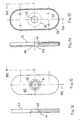
- the fixed upper plate 20 is illustrated in detail in figures 3 and 12: it is symmetrical in respect of two orthogonal horizontal axes and its width is equal to approximately 5-7 times the radius R, while its length is approximately equal to 12-16 times the radius R.
- the two ends 33 of the refractory plate 30 are shaped as semicircles with centres 34. The distance between the centres 34 and 35 corresponds roughly to double the relative travel of the fixed and mobile plates. In this way the distribution of the refractory material is optimized, as its free edges are always at the same distance from the area in contact with the molten steel, whatever the working position of the distribution device may be.
- the fixed upper refractory plate 30 has a metal covering 60 consisting of a sheet of lamina 61 which covers the contour of the plate 30 and has an outer edge 62.
- the height of this edge 62 is approximately equal to the thickness of the plate 30 and its upper edge 63 is curved slightly outwards, as shown in the close-up of figure 12, so as to strengthen the covering itself and allow easy insertion of the plate 30 inside the covering 60 during assembly, without excessive clearances and consequent excessive thickness of the layer of refractory mortar 64 located between the plate 30 and the covering 60.
- the covering 60 also has on the bottom 61 a circular opening 65, the rim 66 of which is folded inwards into an arch so as to create a supporting surface for the refractory plate which is supported at a pre-estabished height from the bottom 61 of the covering.
- the height of this rim 66 also defines the thickness of the layer of mortar.
- the thickness of the layer of mortar 64 is also ensured by protrusions 67 made by presswork and arranged on the bottom 61.
- the circular opening 65 in the bottom of the covering 60 is larger than the outside diameter of the internal pouring appliance 20, so that there is no interference, as shown in figure 1.
- the sliding refractory plate 40 differs from the fixed refractory plate 30 in that the circular groove 41 has a smaller diameter in view of the lesser thickness of the lower refractory sleeve 50 as compared to the thickness of the internal pouring appliance 20.
- This difference between the plates 30 and 40 on the one hand and the refractory sleeves 20 and 50 on the other, is very important for the purposes of the invention. Indeed the internal pouring appliance 20 wears out more quickly than the sleeve 50 in the hole of which the flow of liquid steel is already perfectly directed along vertical flowlines.
- the refractory sleeve 50 As far as concerns the refractory sleeve 50, it should be noted that it too has a metal casing 56, with a double sloping truncated cone shape.
- the lower part 58 supports directly the weight of the sleeve 50, while the upper part 57 defines a meatus with a decreasing thickness inside which the connecting refractory mortar is placed.
Landscapes
- Engineering & Computer Science (AREA)
- Mechanical Engineering (AREA)
- Casting Support Devices, Ladles, And Melt Control Thereby (AREA)
- Sliding Valves (AREA)
- Furnace Charging Or Discharging (AREA)
- Lift Valve (AREA)
Priority Applications (7)
| Application Number | Priority Date | Filing Date | Title |
|---|---|---|---|
| EP89830243A EP0400257B1 (fr) | 1989-06-02 | 1989-06-02 | Dispositif de fermeture à coulisse, en matériau réfractaire, pour récipients métallurgiques |
| DE198989830243T DE400257T1 (de) | 1989-06-02 | 1989-06-02 | Schieberverschluss aus einer feuerfesten masse fuer metallurgische behaelter. |
| AT89830243T ATE136828T1 (de) | 1989-06-02 | 1989-06-02 | Schieberverschluss aus einer feuerfesten masse für metallurgische behälter |
| ES89830243T ES2020156A4 (es) | 1989-06-02 | 1989-06-02 | Valvula de puerta deslizable hecha de un material refractario para vasijas metalurgicas |
| DE68926293T DE68926293T2 (de) | 1989-06-02 | 1989-06-02 | Schieberverschluss aus einer feuerfesten Masse für metallurgische Behälter |
| US07/563,959 US5000362A (en) | 1989-06-02 | 1990-08-07 | Shut-off device made of refractory material for a slide-gate pouring appliance |
| GR91300051T GR910300051T1 (en) | 1989-06-02 | 1991-11-15 | Slide gate valve made of a refractory material for metallurgical vessels |
Applications Claiming Priority (1)
| Application Number | Priority Date | Filing Date | Title |
|---|---|---|---|
| EP89830243A EP0400257B1 (fr) | 1989-06-02 | 1989-06-02 | Dispositif de fermeture à coulisse, en matériau réfractaire, pour récipients métallurgiques |
Publications (2)
| Publication Number | Publication Date |
|---|---|
| EP0400257A1 true EP0400257A1 (fr) | 1990-12-05 |
| EP0400257B1 EP0400257B1 (fr) | 1996-04-17 |
Family
ID=8203223
Family Applications (1)
| Application Number | Title | Priority Date | Filing Date |
|---|---|---|---|
| EP89830243A Expired - Lifetime EP0400257B1 (fr) | 1989-06-02 | 1989-06-02 | Dispositif de fermeture à coulisse, en matériau réfractaire, pour récipients métallurgiques |
Country Status (5)
| Country | Link |
|---|---|
| EP (1) | EP0400257B1 (fr) |
| AT (1) | ATE136828T1 (fr) |
| DE (2) | DE400257T1 (fr) |
| ES (1) | ES2020156A4 (fr) |
| GR (1) | GR910300051T1 (fr) |
Cited By (2)
| Publication number | Priority date | Publication date | Assignee | Title |
|---|---|---|---|---|
| ES2113271A1 (es) * | 1994-09-07 | 1998-04-16 | Krosaki Corp | Estructura de fijacion de bastidor de placa metalica para tobera deslizante. |
| DE10066084B4 (de) * | 1999-09-10 | 2007-03-15 | Yamaha Corp., Hamamatsu | Tastenmusikinstrument mit Sichtanzeigeeinheit |
Families Citing this family (1)
| Publication number | Priority date | Publication date | Assignee | Title |
|---|---|---|---|---|
| DE102021004626A1 (de) | 2021-09-14 | 2023-03-16 | PiRé Feuerfeste Produkte GmbH & Co. KG | Verfahren zur Reparatur eines Schieberverschlusses |
Citations (5)
| Publication number | Priority date | Publication date | Assignee | Title |
|---|---|---|---|---|
| LU59070A1 (fr) * | 1968-07-11 | 1969-11-20 | ||
| FR2257374A1 (fr) * | 1974-01-16 | 1975-08-08 | Uss Eng & Consult | |
| FR2433384A1 (fr) * | 1978-08-19 | 1980-03-14 | Stopinc Ag | Dispositif de fermeture a tiroir a trois plaques |
| GB2040423A (en) * | 1979-01-15 | 1980-08-28 | Sanac Spa | Improved refractory plate with metallic covering |
| GB2163079A (en) * | 1982-08-20 | 1986-02-19 | Flo Con Syst | Pressure plate for sliding gate valve |
-
1989
- 1989-06-02 EP EP89830243A patent/EP0400257B1/fr not_active Expired - Lifetime
- 1989-06-02 ES ES89830243T patent/ES2020156A4/es active Pending
- 1989-06-02 AT AT89830243T patent/ATE136828T1/de not_active IP Right Cessation
- 1989-06-02 DE DE198989830243T patent/DE400257T1/de active Pending
- 1989-06-02 DE DE68926293T patent/DE68926293T2/de not_active Expired - Fee Related
-
1991
- 1991-11-15 GR GR91300051T patent/GR910300051T1/el unknown
Patent Citations (5)
| Publication number | Priority date | Publication date | Assignee | Title |
|---|---|---|---|---|
| LU59070A1 (fr) * | 1968-07-11 | 1969-11-20 | ||
| FR2257374A1 (fr) * | 1974-01-16 | 1975-08-08 | Uss Eng & Consult | |
| FR2433384A1 (fr) * | 1978-08-19 | 1980-03-14 | Stopinc Ag | Dispositif de fermeture a tiroir a trois plaques |
| GB2040423A (en) * | 1979-01-15 | 1980-08-28 | Sanac Spa | Improved refractory plate with metallic covering |
| GB2163079A (en) * | 1982-08-20 | 1986-02-19 | Flo Con Syst | Pressure plate for sliding gate valve |
Cited By (2)
| Publication number | Priority date | Publication date | Assignee | Title |
|---|---|---|---|---|
| ES2113271A1 (es) * | 1994-09-07 | 1998-04-16 | Krosaki Corp | Estructura de fijacion de bastidor de placa metalica para tobera deslizante. |
| DE10066084B4 (de) * | 1999-09-10 | 2007-03-15 | Yamaha Corp., Hamamatsu | Tastenmusikinstrument mit Sichtanzeigeeinheit |
Also Published As
| Publication number | Publication date |
|---|---|
| ES2020156A4 (es) | 1991-08-01 |
| EP0400257B1 (fr) | 1996-04-17 |
| ATE136828T1 (de) | 1996-05-15 |
| DE68926293T2 (de) | 1996-09-19 |
| DE400257T1 (de) | 1991-05-23 |
| GR910300051T1 (en) | 1991-11-15 |
| DE68926293D1 (de) | 1996-05-23 |
Similar Documents
| Publication | Publication Date | Title |
|---|---|---|
| TWI454326B (zh) | 傾注噴嘴 | |
| KR0144365B1 (ko) | 슬라이딩 게이트 밸브용 밸브판 및 밸브 | |
| US4327847A (en) | Sliding gate nozzles | |
| EP0400257B1 (fr) | Dispositif de fermeture à coulisse, en matériau réfractaire, pour récipients métallurgiques | |
| US5000362A (en) | Shut-off device made of refractory material for a slide-gate pouring appliance | |
| BR0305780B1 (pt) | amortecedor de impacto para distribuidor. | |
| EP1289696A1 (fr) | Buse de coulee en une piece et dispositif de serrage pour maintenir une telle buse | |
| JPS60116711A (ja) | 冶金容器のためのガスバブル煉瓦 | |
| RU2181316C2 (ru) | Устройство для замены труб в промежуточном разливочном ковше, узел пластины трубы (варианты) и пластина, закрепленная в устройстве для замены труб | |
| JPH0339786B2 (fr) | ||
| UA75398C2 (en) | Method for preventing a vortex effect in the discharge area of a metallurgical melting vessel | |
| RU2561619C2 (ru) | Огнеупорный блок для шиберного затвора в сливном отверстии емкости для металлического расплава | |
| EP0218082B1 (fr) | Tiroir glissant et méthode d'actionnement | |
| EP0080335B1 (fr) | Dispositif pour rendre étanche les électrodes d'un four à arc électrique | |
| EP1407843A1 (fr) | Dispositif d'alimentation en metal en fusion | |
| AU754954B2 (en) | Closure plate and a slide gate on the outlet of a container containing molten metal | |
| KR20130140763A (ko) | 용융 금속을 수용하는 용기의 스파우트 상의 미끄럼 밀폐부 및 밀폐 플레이트 | |
| CN212436768U (zh) | 一种浇水壶壶盖 | |
| JP7345368B2 (ja) | スライディングゲートのコレクターノズル及びその使用方法 | |
| FI77392C (fi) | Skjutportsventil. lisaeys patenttiin 56633 - tillaegg till patent 56633 | |
| EP0733423B1 (fr) | Système de coulée avec dispositif de fermeture coulissante pour la régulation du jet de coulée sortant d'un récipient de coulée | |
| JPH1157987A (ja) | 冶金容器及びその耐火物水平化アセンブリ | |
| US20040191097A1 (en) | Molten metal feeder | |
| JPH03102192A (ja) | 冶金容器用の閉鎖兼調整機構 | |
| JP7347940B2 (ja) | 撹拌装置 |
Legal Events
| Date | Code | Title | Description |
|---|---|---|---|
| PUAI | Public reference made under article 153(3) epc to a published international application that has entered the european phase |
Free format text: ORIGINAL CODE: 0009012 |
|
| AK | Designated contracting states |
Kind code of ref document: A1 Designated state(s): AT BE CH DE ES FR GB GR LI LU NL SE |
|
| TCNL | Nl: translation of patent claims filed | ||
| TCAT | At: translation of patent claims filed | ||
| EL | Fr: translation of claims filed | ||
| DET | De: translation of patent claims | ||
| 17P | Request for examination filed |
Effective date: 19901205 |
|
| 17Q | First examination report despatched |
Effective date: 19930806 |
|
| RAP1 | Party data changed (applicant data changed or rights of an application transferred) |
Owner name: ILVA S.P.A. Owner name: VESUVIUS ITALIA S.P.A. |
|
| GRAA | (expected) grant |
Free format text: ORIGINAL CODE: 0009210 |
|
| AK | Designated contracting states |
Kind code of ref document: B1 Designated state(s): AT BE CH DE ES FR GB GR LI LU NL SE |
|
| PG25 | Lapsed in a contracting state [announced via postgrant information from national office to epo] |
Ref country code: NL Free format text: LAPSE BECAUSE OF FAILURE TO SUBMIT A TRANSLATION OF THE DESCRIPTION OR TO PAY THE FEE WITHIN THE PRESCRIBED TIME-LIMIT Effective date: 19960417 Ref country code: LI Free format text: LAPSE BECAUSE OF FAILURE TO SUBMIT A TRANSLATION OF THE DESCRIPTION OR TO PAY THE FEE WITHIN THE PRESCRIBED TIME-LIMIT Effective date: 19960417 Ref country code: GR Free format text: LAPSE BECAUSE OF FAILURE TO SUBMIT A TRANSLATION OF THE DESCRIPTION OR TO PAY THE FEE WITHIN THE PRESCRIBED TIME-LIMIT Effective date: 19960417 Ref country code: FR Effective date: 19960417 Ref country code: CH Free format text: LAPSE BECAUSE OF FAILURE TO SUBMIT A TRANSLATION OF THE DESCRIPTION OR TO PAY THE FEE WITHIN THE PRESCRIBED TIME-LIMIT Effective date: 19960417 Ref country code: BE Effective date: 19960417 Ref country code: AT Effective date: 19960417 |
|
| REF | Corresponds to: |
Ref document number: 136828 Country of ref document: AT Date of ref document: 19960515 Kind code of ref document: T |
|
| REG | Reference to a national code |
Ref country code: CH Ref legal event code: NV Representative=s name: KATZAROV S.A. |
|
| REF | Corresponds to: |
Ref document number: 68926293 Country of ref document: DE Date of ref document: 19960523 |
|
| PG25 | Lapsed in a contracting state [announced via postgrant information from national office to epo] |
Ref country code: ES Free format text: LAPSE BECAUSE OF THE APPLICANT RENOUNCES Effective date: 19960603 |
|
| PG25 | Lapsed in a contracting state [announced via postgrant information from national office to epo] |
Ref country code: LU Free format text: LAPSE BECAUSE OF NON-PAYMENT OF DUE FEES Effective date: 19960630 |
|
| PG25 | Lapsed in a contracting state [announced via postgrant information from national office to epo] |
Ref country code: SE Effective date: 19960717 Ref country code: GB Effective date: 19960717 |
|
| GRAH | Despatch of communication of intention to grant a patent |
Free format text: ORIGINAL CODE: EPIDOS IGRA |
|
| EN | Fr: translation not filed | ||
| NLV1 | Nl: lapsed or annulled due to failure to fulfill the requirements of art. 29p and 29m of the patents act | ||
| REG | Reference to a national code |
Ref country code: CH Ref legal event code: PL |
|
| PLBQ | Unpublished change to opponent data |
Free format text: ORIGINAL CODE: EPIDOS OPPO |
|
| PLBI | Opposition filed |
Free format text: ORIGINAL CODE: 0009260 |
|
| PLBF | Reply of patent proprietor to notice(s) of opposition |
Free format text: ORIGINAL CODE: EPIDOS OBSO |
|
| PG25 | Lapsed in a contracting state [announced via postgrant information from national office to epo] |
Ref country code: DE Effective date: 19970301 |
|
| 26 | Opposition filed |
Opponent name: NUOVA SIRMA SPA Effective date: 19970115 |
|
| GBPC | Gb: european patent ceased through non-payment of renewal fee |
Effective date: 19960717 |
|
| PLBF | Reply of patent proprietor to notice(s) of opposition |
Free format text: ORIGINAL CODE: EPIDOS OBSO |
|
| REG | Reference to a national code |
Ref country code: ES Ref legal event code: FD2A Effective date: 19991007 |
|
| PLBO | Opposition rejected |
Free format text: ORIGINAL CODE: EPIDOS REJO |
|
| PLBN | Opposition rejected |
Free format text: ORIGINAL CODE: 0009273 |
|
| STAA | Information on the status of an ep patent application or granted ep patent |
Free format text: STATUS: OPPOSITION REJECTED |
|
| 27O | Opposition rejected |
Effective date: 20000112 |