EP0400271A2 - Hochspannungsgenerator-Einrichtung vom Typ eines in mehrfachen Stufen isolierenden Transformators - Google Patents
Hochspannungsgenerator-Einrichtung vom Typ eines in mehrfachen Stufen isolierenden Transformators Download PDFInfo
- Publication number
- EP0400271A2 EP0400271A2 EP90103604A EP90103604A EP0400271A2 EP 0400271 A2 EP0400271 A2 EP 0400271A2 EP 90103604 A EP90103604 A EP 90103604A EP 90103604 A EP90103604 A EP 90103604A EP 0400271 A2 EP0400271 A2 EP 0400271A2
- Authority
- EP
- European Patent Office
- Prior art keywords
- magnetic core
- rectifier
- potential
- rectifier circuits
- high voltage
- Prior art date
- Legal status (The legal status is an assumption and is not a legal conclusion. Google has not performed a legal analysis and makes no representation as to the accuracy of the status listed.)
- Granted
Links
Images

Classifications
-
- H—ELECTRICITY
- H02—GENERATION; CONVERSION OR DISTRIBUTION OF ELECTRIC POWER
- H02M—APPARATUS FOR CONVERSION BETWEEN AC AND AC, BETWEEN AC AND DC, OR BETWEEN DC AND DC, AND FOR USE WITH MAINS OR SIMILAR POWER SUPPLY SYSTEMS; CONVERSION OF DC OR AC INPUT POWER INTO SURGE OUTPUT POWER; CONTROL OR REGULATION THEREOF
- H02M7/00—Conversion of AC power input into DC power output; Conversion of DC power input into AC power output
- H02M7/02—Conversion of AC power input into DC power output without possibility of reversal
- H02M7/04—Conversion of AC power input into DC power output without possibility of reversal by static converters
- H02M7/06—Conversion of AC power input into DC power output without possibility of reversal by static converters using discharge tubes without control electrode or semiconductor devices without control electrode
- H02M7/10—Conversion of AC power input into DC power output without possibility of reversal by static converters using discharge tubes without control electrode or semiconductor devices without control electrode arranged for operation in series, e.g. for multiplication of voltage
- H02M7/103—Containing passive elements (capacitively coupled) which are ordered in cascade on one source
-
- H—ELECTRICITY
- H01—ELECTRIC ELEMENTS
- H01F—MAGNETS; INDUCTANCES; TRANSFORMERS; SELECTION OF MATERIALS FOR THEIR MAGNETIC PROPERTIES
- H01F38/00—Adaptations of transformers or inductances for specific applications or functions
- H01F38/18—Rotary transformers
Definitions
- This invention relates to a high voltage generating apparatus for use in accelerating charged particles or the like, which generates a DC high voltage by rectifying and smoothing an AC voltage with diodes and capacitors.
- Known high voltage generating apparatus include the Cockcroft-Walton type, Schenkel type and insulating transformer type.
- a rectifier circuit With the Cockcroft-Walton type and Schenkel type high voltage generating apparatus, a rectifier circuit must be formed with many diodes and capacitors connected in multiple stages. This entails an increase in ripples, and a deterioration in control characteristics due to a response delay in following load variations.
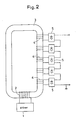
- This insulating transformer type high voltage generating apparatus comprises a driver 1, a primary coil 2 connected to the driver 1 and wound around an insulating magnetic core 3, a plurality of secondary coil 4 wound around the core 3, and rectifier circuits 5 connected to the secondary coils 4.
- the rectifier circuits 5 each including a diode and a capacitor have DC outputs connected in series to provide a DC high voltage.
- the diodes and capacitors constituting the rectifier circuits 5 may have a low voltage characteristic if the number of rectifier circuits is increased. Despite the increase in the number of rectifier circuits, the ripples can be lowered compared with a multi-stage Cockcroft-Walton type apparatus. Further, only a minor delay occurs in responding to load variations, and hence an excellent control characteristic is expected.
- discharge may occur between the secondary coils 4 and surfaces of the insulating core 3, if a very high voltage through the insulating core 3 is used. Also the insulating material forming the core 3 may lose its insulation according to an internal discharge. Thus, there is a limit to the increase of voltage.
- This invention has been made having regard to the state of the art noted above, and its object is to provide a high voltage generating apparatus which requires components of rectifier circuits having a low voltage characteristic, involves only minor ripples, provides excellent control characteristics in relation to load variations, and yet is capable of preventing discharge externally and internally of the magnetic cores to generate a sufficiently high voltage.
- a multi-stage insulating transformer type high voltage generating apparatus comprises a plurality of magnetic cores each having a transmitting coil and a receiving coil wound therearound, the receiving coil of a first one of the magnetic cores being connected to a driver, the transmitting coil of one of adjacent magnetic cores being connected to the receiving coil of the other of the magnetic cores through a transmitting line, and a plurality of rectifier circuits connected to the magnetic cores through individual secondary coils, respectively, the rectifier circuits being successively connected in series to provide a high DC voltage, wherein each magnetic core has a potential fixed equal or close to an output potential of the rectifier circuit of the plurality of rectifier circuits wound therearound which puts out a mean potential, and each transmitting line has a potential fixed equal or close to a potential of a connecting point between a final rectifier circuit provided for a preceding magnetic core and a foremost rectifier circuit provided for a next magnetic core.
- the high voltage generating apparatus comprises the insulating transformer type. Therefore, a sufficiently high voltage may be generated by increasing the number of rectifier circuits even if individual diodes and capacitors have a low voltage characteristic.
- the overall ripple is the sum of those of recti fier circuits. However, one can connect two adjacent rectifier circuits in anti-phase of ripples, and the sum ripple becomes small enough. Further, only a minor delay occurs in responding to load variations, and the control characteristics are excellent.
- each magnetic core is fixed to a certain potential to reduce its potential difference from that of the secondary coils
- the potential of each transmitting line is fixed to a certain potential to reduce its potential difference from the potential of the magnetic core. This prevents discharge between the secondary coils and magnetic cores, between the transmitting and receiving coils and magnetic cores, and internally of the magnetic cores.
- the apparatus includes the rectifier circuits formed of components having a relatively low voltage characteristic, and is capable of generating a sufficiently high voltage while preventing discharge externally and internally of the magnetic cores.
- Fig. 1 is a circuit diagram of a multi-stage insulating transformer type high voltage generating apparatus.
- This apparatus comprises three magnetic cores B1, B2 and B3 formed of ferrite, for example, and arranged in series.
- a receiving coil D1 and a transmitting coil D2 are wound around the magnetic core B1, a receiving coil D3 and a transmitting coil D4 around the magnetic core B2, and a receiving coil D5 around the magnetic core B3.
- the receiving coil D1 is connected to a driver A which puts out an AC high voltage.
- the transmitting coil D2 and receiving coil D3 are interconnected through a transmission line F1.
- the transmitting coil D4 and receiving coil D5 are interconnected through a transmission line F2.
- a three-stage insulating transformer is formed.
- Two secondary coils E11 and E12 are wound around the magnetic core B1 and connected to rectifier circuits C11 and C12, respectively.
- secondary coils E21 and E22 are wound around the magnetic core B2 and connected to rectifier circuits C21 and C22.
- secondary coils E31 and E32 are wound around the magnetic core B3 and connected to rectifier circuits C31 and C32.
- the rectifier circuits C11-C32 have DC outputs connected in series.
- Each of the rectifier circuits C11-C32 comprises a few stage Cockcroft-Walton type rectifier circuit.
- this high voltage generating apparatus is the insulating transformer type, its overall ripple is made to correspond to the sum ripple of the whole rectifier circuits.
- two adjacent circuits C11 and C12, for example
- the overall ripple is minimized. Consequently, it is possible to render the ripple quite low despite the increase in the number of rectifier circuits. Further, only a minor delay occurs in responding to load variations, and hence excellent control characteristics.
- a connecting point P1 between the pair of rectifier circuits C11 and C12 wound around the magnetic core B1 and a selected point Q1 of the magnetic core B1 are interconnected through a conductive wire G1.
- a connecting point P2 between the pair of rectifier circuits C21 and C22 wound around the magnetic core B2 and a selected point Q2 of the magnetic core B2 are interconnected through a conductive wire G2.
- a connecting point P3 between the pair of rectifier circuits C31 and C32 wound around the magnetic core B3 and a selected point Q3 of the magnetic core B3 are interconnected through a conductive wire G3.
- each of the magnetic cores B1, B2 and B3 has a potential fixed equal to an output potential of the rectifier circuit C11, C21 or C31 having a mean potential of the pair of rectifier circuits C11 and C12, C21 and C22, or C31 and C32 wound around that magnetic core.
- a connecting point P4 between the rectifier circuits C12 and C21 and a point Q4 on the transmission line F1 are interconnected through a conductive wire G4.
- a connecting point P5 between the rectifier circuits C22 and C31 and a point Q5 on the transmission line F2 are also interconnected through a conductive wire G5.
- the transmission line F1 (or F2) has a potential fixed equal to the potential at the connecting point P4 (or P5) between the final rectifier circuit C12 (or C22) wound around the preceding magnetic core B1 (or B2) and the first rectifier circuit C21 (or C31) wound around the next magnetic core B2 (or B3).
- the multi-stage insulating transformer type high voltage generating apparatus Assuming that each of the rectifier circuits C11-C32 provides a DC output voltage V0, the multi-stage insulating transformer type high voltage generating apparatus with the rectifier circuits connected in series provides a DC output voltage 6 times V0. Thus, a high voltage is obtained.
- the magnetic core B3 would have an indefinite potential in contrast to the very high voltage, 6 x V0, of the secondary coil E32. Because of the very large potential difference between the secondary coil E32 and magnetic core B3, discharge could occur between the secondary coil E32 and the surface of magnetic core B3 and inside the magnetic core B3.
- the connecting point P3 by interconnecting the connecting point P3 and magnetic core B3 through the conductive wire G3, the potential of magnetic core B3 is raised and fixed to a potential level at the connecting point P3.
- the secondary coil E22 has a potential 4 times V0.
- the magnetic core B2 has a potential 3 times V0 since it is connected to the connecting point P2 through the conductive wire G2.
- the potential difference between the secondary coil E22 and magnetic core B2 is also V0.
- the conductive wire G5 is provided for interconnecting the connecting point P5 and transmission line F2, the potential of transmission line F2, and thus the potentials of transmitting coil D4 and receiving coil D5 are fixed to the potential at the connecting point P5. Since the connecting point P5 has a potential 4 times V0, the transmitting coil D4 and receiving coil D5 also have a potential 4 times V0.
- the magnetic core B3 has a potential 5 times V0 as already noted, and therefore the potential difference between the receiving coil D5 and magnetic core B3 is V0, thereby preventing discharge between the receiving coil D5 and magnetic core B3.
- the magnetic core B2 has a potential 3 times V0, and therefore the potential difference between the transmitting coil D4 and magnetic core B2 is V0, which prevents discharge between the transmitting coil D4 and magnetic core B2.
- the apparatus according to this invention is capable of generating a sufficiently high voltage while preventing discharge externally and internally of the magnetic cores, although components having a low voltage characteristic are used to form the rectifier circuits.
- the following wiring construction may be employed to raise and fix the potentials of the respective magnetic cores to potentials close to the potentials of the transmitting coils and receiving coils, and to raise and fix the potentials of the respective transmission lines to potentials close to the potentials of the magnetic cores.
- dividing resistors R1-R6 may be provided between the output end of the final rectifier circuit C32 and the ground for dividing the voltage obtained from the rectifier circuit C32 into a plurality of voltages and selectively taking out these voltages.
- the conductive wires G1-G5 may be replaced with connections between the point Q1 and a point S1, between the point Q4 and a point S2, between the point Q2 and a point S3, between the point Q5 and a point S4 and between the point Q3 and a point S5.
- Each of the foregoing embodiments includes three magnetic cores, and two secondary coils and two rectifier circuits connected to each magnetic core, but these numbers are optional. Where four rectifier circuits are provided for each magnetic core, for example, the connecting point between the second and third rectifier circuits is connected to the magnetic core. In the case of six rectifier circuits for each magnetic core, the connecting point between the third and fourth rectifier circuits is connected to the magnetic core.
Landscapes
- Engineering & Computer Science (AREA)
- Power Engineering (AREA)
- Rectifiers (AREA)
Applications Claiming Priority (2)
| Application Number | Priority Date | Filing Date | Title |
|---|---|---|---|
| JP1139464A JPH0710175B2 (ja) | 1989-05-31 | 1989-05-31 | 多段式絶縁変圧器型高電圧発生装置 |
| JP139464/89 | 1989-05-31 |
Publications (3)
| Publication Number | Publication Date |
|---|---|
| EP0400271A2 true EP0400271A2 (de) | 1990-12-05 |
| EP0400271A3 EP0400271A3 (de) | 1991-01-09 |
| EP0400271B1 EP0400271B1 (de) | 1994-05-04 |
Family
ID=15245843
Family Applications (1)
| Application Number | Title | Priority Date | Filing Date |
|---|---|---|---|
| EP90103604A Expired - Lifetime EP0400271B1 (de) | 1989-05-31 | 1990-02-24 | Hochspannungsgenerator-Einrichtung vom Typ eines in mehrfachen Stufen isolierenden Transformators |
Country Status (4)
| Country | Link |
|---|---|
| US (1) | US5079687A (de) |
| EP (1) | EP0400271B1 (de) |
| JP (1) | JPH0710175B2 (de) |
| DE (1) | DE69008618T2 (de) |
Families Citing this family (5)
| Publication number | Priority date | Publication date | Assignee | Title |
|---|---|---|---|---|
| US5625545A (en) * | 1994-03-01 | 1997-04-29 | Halmar Robicon Group | Medium voltage PWM drive and method |
| JP3372178B2 (ja) * | 1996-12-25 | 2003-01-27 | 愛好電機株式会社 | 3相式電圧自動切替装置付き省電力装置 |
| KR100857769B1 (ko) * | 2008-01-11 | 2008-09-09 | 주식회사 동양이지텍 | 무선안테나를 이용한 온수매트용 온도조절기의 전자파자동차폐장치 |
| US10398011B2 (en) | 2015-11-12 | 2019-08-27 | Kimtron, Inc. | Method and apparatus for active filament management |
| US10342107B2 (en) | 2015-11-12 | 2019-07-02 | Kimtron, Inc. | Cascaded filament transformer within a resistive shroud |
Family Cites Families (10)
| Publication number | Priority date | Publication date | Assignee | Title |
|---|---|---|---|---|
| DE1225290B (de) * | 1964-07-23 | 1966-09-22 | Messwandler Bau Gmbh | Spannungswandler |
| US3541424A (en) * | 1969-05-19 | 1970-11-17 | Sumitomo Electric Industries | High voltage generating device |
| US3596167A (en) * | 1969-08-14 | 1971-07-27 | Deltaray Corp | Cascade transformer high voltage generator |
| FR2106643A5 (en) * | 1970-09-18 | 1972-05-05 | Anvar | High tension power supply - for linear accelerator ion source |
| US3729650A (en) * | 1972-02-07 | 1973-04-24 | R Cook | Potential-current transformer device |
| US4087701A (en) * | 1977-02-10 | 1978-05-02 | General Electric Company | Transformer cascade for powering electronics on high voltage transmission lines |
| JPS5728572A (en) * | 1980-07-25 | 1982-02-16 | Origin Electric Co Ltd | Dc high voltage generator |
| US4392173A (en) * | 1981-12-14 | 1983-07-05 | Ford Aerospace & Communications Corporation | Circuit for reducing voltage stress across a transformer |
| SU1181094A1 (ru) * | 1984-04-05 | 1985-09-23 | Ленинградское научно-производственное объединение "Буревестник" | Однофазный каскадный генератор |
| JP6235349B2 (ja) | 2014-01-16 | 2017-11-22 | シャープ株式会社 | タッチ操作機能付表示装置 |
-
1989
- 1989-05-31 JP JP1139464A patent/JPH0710175B2/ja not_active Expired - Fee Related
-
1990
- 1990-02-24 EP EP90103604A patent/EP0400271B1/de not_active Expired - Lifetime
- 1990-02-24 DE DE69008618T patent/DE69008618T2/de not_active Expired - Fee Related
- 1990-02-26 US US07/484,323 patent/US5079687A/en not_active Expired - Fee Related
Also Published As
| Publication number | Publication date |
|---|---|
| EP0400271B1 (de) | 1994-05-04 |
| DE69008618T2 (de) | 1994-08-18 |
| EP0400271A3 (de) | 1991-01-09 |
| US5079687A (en) | 1992-01-07 |
| DE69008618D1 (de) | 1994-06-09 |
| JPH037067A (ja) | 1991-01-14 |
| JPH0710175B2 (ja) | 1995-02-01 |
Similar Documents
| Publication | Publication Date | Title |
|---|---|---|
| EP0100098B1 (de) | Gleichstromumformer für Fernstromversorgung | |
| US4978906A (en) | Picture frame matrix transformer | |
| JP3466118B2 (ja) | インバータ式駆動装置の漏洩電流低減フィルタ | |
| CN111902895A (zh) | 屏蔽式电力变压器 | |
| US20120119676A1 (en) | Flyback power converter with divided energy transfer element | |
| US7274280B1 (en) | Nine-phase step-up/step-down autotransformer | |
| US20220270816A1 (en) | Transformer and switching power supply apparatus for reducing common mode noise due to line-to-ground capacitances | |
| US5079687A (en) | Multi-stage insulating transformer type high voltage generating apparatus having a connection structure | |
| EP0980035A1 (de) | Einphasiger Transformator mit Mittelabgriff | |
| US20040190312A1 (en) | Switching power supply | |
| US4725739A (en) | AC branch power distribution filter | |
| WO2020195276A1 (ja) | スイッチング電源装置 | |
| JP4879813B2 (ja) | スイッチング電源装置 | |
| US4716512A (en) | Multiple step-up rectifier circuit | |
| CN217824765U (zh) | 用在梯度功率放大器中的输出滤波器 | |
| JP3201383B2 (ja) | 共振型電源用トランス | |
| US6272032B1 (en) | Rectifier with midpoint feed | |
| JPH04244783A (ja) | 多段式絶縁変圧器型高電圧発生装置 | |
| JPS59201682A (ja) | インバ−タ | |
| JP2504329B2 (ja) | 多段式絶縁変圧器型高電圧発生装置 | |
| JPH04271280A (ja) | 多段式絶縁変圧器型高電圧発生装置 | |
| CN112802674A (zh) | 一种多输入选择的三相隔离变压器 | |
| US4057717A (en) | Transformer with active elements | |
| US5001401A (en) | Dual voltage ballast | |
| JPH08130875A (ja) | 直流電源装置 |
Legal Events
| Date | Code | Title | Description |
|---|---|---|---|
| PUAI | Public reference made under article 153(3) epc to a published international application that has entered the european phase |
Free format text: ORIGINAL CODE: 0009012 |
|
| PUAL | Search report despatched |
Free format text: ORIGINAL CODE: 0009013 |
|
| AK | Designated contracting states |
Kind code of ref document: A2 Designated state(s): DE FR GB |
|
| AK | Designated contracting states |
Kind code of ref document: A3 Designated state(s): DE FR GB |
|
| 17P | Request for examination filed |
Effective date: 19901228 |
|
| 17Q | First examination report despatched |
Effective date: 19930208 |
|
| GRAA | (expected) grant |
Free format text: ORIGINAL CODE: 0009210 |
|
| AK | Designated contracting states |
Kind code of ref document: B1 Designated state(s): DE FR GB |
|
| REF | Corresponds to: |
Ref document number: 69008618 Country of ref document: DE Date of ref document: 19940609 |
|
| PLBI | Opposition filed |
Free format text: ORIGINAL CODE: 0009260 |
|
| ET | Fr: translation filed | ||
| 26 | Opposition filed |
Opponent name: SIEMENS AG Effective date: 19940725 |
|
| PLBN | Opposition rejected |
Free format text: ORIGINAL CODE: 0009273 |
|
| STAA | Information on the status of an ep patent application or granted ep patent |
Free format text: STATUS: OPPOSITION REJECTED |
|
| 27O | Opposition rejected |
Effective date: 19951204 |
|
| REG | Reference to a national code |
Ref country code: GB Ref legal event code: 746 Effective date: 19970110 |
|
| REG | Reference to a national code |
Ref country code: FR Ref legal event code: D6 |
|
| PGFP | Annual fee paid to national office [announced via postgrant information from national office to epo] |
Ref country code: FR Payment date: 20010213 Year of fee payment: 12 |
|
| PGFP | Annual fee paid to national office [announced via postgrant information from national office to epo] |
Ref country code: GB Payment date: 20010221 Year of fee payment: 12 Ref country code: DE Payment date: 20010221 Year of fee payment: 12 |
|
| REG | Reference to a national code |
Ref country code: GB Ref legal event code: IF02 |
|
| PG25 | Lapsed in a contracting state [announced via postgrant information from national office to epo] |
Ref country code: GB Free format text: LAPSE BECAUSE OF NON-PAYMENT OF DUE FEES Effective date: 20020224 |
|
| PG25 | Lapsed in a contracting state [announced via postgrant information from national office to epo] |
Ref country code: DE Free format text: LAPSE BECAUSE OF NON-PAYMENT OF DUE FEES Effective date: 20020903 |
|
| GBPC | Gb: european patent ceased through non-payment of renewal fee |
Effective date: 20020224 |
|
| PG25 | Lapsed in a contracting state [announced via postgrant information from national office to epo] |
Ref country code: FR Free format text: LAPSE BECAUSE OF NON-PAYMENT OF DUE FEES Effective date: 20021031 |
|
| REG | Reference to a national code |
Ref country code: FR Ref legal event code: ST |