EP0400325A2 - Procédé et dispositif de lancement de balles et de génération de spins - Google Patents
Procédé et dispositif de lancement de balles et de génération de spins Download PDFInfo
- Publication number
- EP0400325A2 EP0400325A2 EP90107762A EP90107762A EP0400325A2 EP 0400325 A2 EP0400325 A2 EP 0400325A2 EP 90107762 A EP90107762 A EP 90107762A EP 90107762 A EP90107762 A EP 90107762A EP 0400325 A2 EP0400325 A2 EP 0400325A2
- Authority
- EP
- European Patent Office
- Prior art keywords
- ball
- friction
- departure
- spin
- wheel
- Prior art date
- Legal status (The legal status is an assumption and is not a legal conclusion. Google has not performed a legal analysis and makes no representation as to the accuracy of the status listed.)
- Withdrawn
Links
- 238000000034 method Methods 0.000 title claims description 21
- 230000000694 effects Effects 0.000 claims abstract description 15
- 230000008859 change Effects 0.000 claims abstract description 9
- 235000009854 Cucurbita moschata Nutrition 0.000 claims abstract description 4
- 240000001980 Cucurbita pepo Species 0.000 claims abstract description 4
- 235000009852 Cucurbita pepo Nutrition 0.000 claims abstract description 4
- 235000020354 squash Nutrition 0.000 claims abstract description 4
- 230000001133 acceleration Effects 0.000 claims description 12
- 230000007480 spreading Effects 0.000 claims description 5
- 238000003892 spreading Methods 0.000 claims description 5
- 238000003860 storage Methods 0.000 claims description 4
- 230000001105 regulatory effect Effects 0.000 claims description 3
- 238000005096 rolling process Methods 0.000 claims description 3
- 238000011156 evaluation Methods 0.000 claims 1
- 239000000835 fiber Substances 0.000 claims 1
- 230000006855 networking Effects 0.000 claims 1
- 239000004753 textile Substances 0.000 claims 1
- 230000002093 peripheral effect Effects 0.000 description 4
- 239000000463 material Substances 0.000 description 3
- 230000008569 process Effects 0.000 description 3
- 239000002390 adhesive tape Substances 0.000 description 2
- 239000002783 friction material Substances 0.000 description 2
- 239000004809 Teflon Substances 0.000 description 1
- 229920006362 Teflon® Polymers 0.000 description 1
- 239000000853 adhesive Substances 0.000 description 1
- 230000001070 adhesive effect Effects 0.000 description 1
- 239000011248 coating agent Substances 0.000 description 1
- 238000000576 coating method Methods 0.000 description 1
- 238000010924 continuous production Methods 0.000 description 1
- 238000013016 damping Methods 0.000 description 1
- 230000003247 decreasing effect Effects 0.000 description 1
- 239000013013 elastic material Substances 0.000 description 1
- 238000005265 energy consumption Methods 0.000 description 1
- 239000006260 foam Substances 0.000 description 1
- 230000006870 function Effects 0.000 description 1
- 230000005484 gravity Effects 0.000 description 1
- 230000003993 interaction Effects 0.000 description 1
- 230000009191 jumping Effects 0.000 description 1
- 230000001960 triggered effect Effects 0.000 description 1
- 210000001364 upper extremity Anatomy 0.000 description 1
Images


Classifications
-
- A—HUMAN NECESSITIES
- A63—SPORTS; GAMES; AMUSEMENTS
- A63B—APPARATUS FOR PHYSICAL TRAINING, GYMNASTICS, SWIMMING, CLIMBING, OR FENCING; BALL GAMES; TRAINING EQUIPMENT
- A63B69/00—Training appliances or apparatus for special sports
- A63B69/40—Stationarily-arranged devices for projecting balls or other bodies
-
- A—HUMAN NECESSITIES
- A63—SPORTS; GAMES; AMUSEMENTS
- A63B—APPARATUS FOR PHYSICAL TRAINING, GYMNASTICS, SWIMMING, CLIMBING, OR FENCING; BALL GAMES; TRAINING EQUIPMENT
- A63B69/00—Training appliances or apparatus for special sports
- A63B69/40—Stationarily-arranged devices for projecting balls or other bodies
- A63B2069/402—Stationarily-arranged devices for projecting balls or other bodies giving spin
-
- A—HUMAN NECESSITIES
- A63—SPORTS; GAMES; AMUSEMENTS
- A63B—APPARATUS FOR PHYSICAL TRAINING, GYMNASTICS, SWIMMING, CLIMBING, OR FENCING; BALL GAMES; TRAINING EQUIPMENT
- A63B2102/00—Application of clubs, bats, rackets or the like to the sporting activity ; particular sports involving the use of balls and clubs, bats, rackets, or the like
- A63B2102/16—Table tennis
-
- A—HUMAN NECESSITIES
- A63—SPORTS; GAMES; AMUSEMENTS
- A63B—APPARATUS FOR PHYSICAL TRAINING, GYMNASTICS, SWIMMING, CLIMBING, OR FENCING; BALL GAMES; TRAINING EQUIPMENT
- A63B2210/00—Space saving
- A63B2210/50—Size reducing arrangements for stowing or transport
-
- A—HUMAN NECESSITIES
- A63—SPORTS; GAMES; AMUSEMENTS
- A63B—APPARATUS FOR PHYSICAL TRAINING, GYMNASTICS, SWIMMING, CLIMBING, OR FENCING; BALL GAMES; TRAINING EQUIPMENT
- A63B69/00—Training appliances or apparatus for special sports
- A63B69/002—Training appliances or apparatus for special sports for football
-
- A—HUMAN NECESSITIES
- A63—SPORTS; GAMES; AMUSEMENTS
- A63B—APPARATUS FOR PHYSICAL TRAINING, GYMNASTICS, SWIMMING, CLIMBING, OR FENCING; BALL GAMES; TRAINING EQUIPMENT
- A63B69/00—Training appliances or apparatus for special sports
- A63B69/40—Stationarily-arranged devices for projecting balls or other bodies
- A63B69/406—Stationarily-arranged devices for projecting balls or other bodies with rotating discs, wheels or pulleys gripping and propelling the balls or bodies by friction
-
- A—HUMAN NECESSITIES
- A63—SPORTS; GAMES; AMUSEMENTS
- A63B—APPARATUS FOR PHYSICAL TRAINING, GYMNASTICS, SWIMMING, CLIMBING, OR FENCING; BALL GAMES; TRAINING EQUIPMENT
- A63B69/00—Training appliances or apparatus for special sports
- A63B69/40—Stationarily-arranged devices for projecting balls or other bodies
- A63B69/407—Stationarily-arranged devices for projecting balls or other bodies with spring-loaded propelling means
- A63B69/408—Stationarily-arranged devices for projecting balls or other bodies with spring-loaded propelling means with rotating propelling arm
Definitions
- the ball is made using a device between two counter-rotating discs. It is accelerated and gets its spin at different disc speeds.
- a spin can only be created in one dimension - only forward or backward, but this is not a normal course of the game.
- a table tennis player, a tennis player, squash or soccer player can generate the spin in any direction.
- Another disadvantage is that the change of the departure angle can only be achieved with a high mechanical effort.
- the presented method tries to counter the disadvantages described above with the associated devices.
- the system consists of only one wheel or alternatively a rotating racket with counterweights.
- the ball is pressed between a wheel and a rail and accelerated.
- the friction coefficients can e.g. can be reduced by a Teflon coating or by appropriate processing of the surface.
- the surface of one wheel is elastic and therefore has a high coefficient of friction.
- the size can be significantly reduced by this method.
- a relatively large wheel achieves high peripheral speeds at a low speed, and the larger mass means that the flywheel energy stored is relatively large. Since only energy is consumed when a ball is shot, relatively small drive powers are sufficient. The result is small dimensions of the drive units.
- the striking side is also elastic.
- the racket moves in a closed chamber with an opening for the ball feed in the middle of the housing and an opening for the ball flying out.
- the ball is fed in the middle of the chamber, since the peripheral speeds are relatively low here. Due to gravity and centrifugal force, it moves outwards and is accelerated.
- the walls of this chamber are also designed to be elastic to prevent the ball from jumping. Only the outer tread is inelastic.
- the sizes can still be reduced by driving the wheel via an integrated direct drive or via a flanged angular gear with a motor.
- the drive is carried out by pulleys or gear wheels or roller wheels.
- the energy of a flying ball with spin can be divided into an energy component that serves the forward movement and a component that serves the spin effect.
- the energy component for generating the forward component is much larger than the component for generating the spin effect.
- the process for spin generation does justice to these considerations: With a friction surface that can be moved concentrically around the departure channel, e.g. Any spin effects can be achieved in the form of an elastic roller.
- the spin effect can be generated by the decrease in energy.
- the strength of the spin effect can be changed by changing the coefficient of friction of the surface or by increasing the contact pressure.
- the coefficient of friction is changed by introducing different materials to the ball.
- the roller is coupled to an eddy current brake, the effect of which can be controlled / regulated by changing the load resistance.
- roller system consisting of several rollers is attached around the departure channel. These are moved into the departure channel as required.
- the change in the take-off angle is achieved by changing the position of the entire device with the aid of an adjusting screw.
- the set screw is driven by a motor, so that any angle can be reached during the course of the game.
- the departure angle is changed by changing the position of the counter pressure rails relative to the main wheel.
- This rail is designed flexibly in this variant. Since this rail is arranged concentrically around the main wheel, it only needs to be raised or lowered. Due to the centrifugal force, the ball will always be oriented towards the rail.
- the balls are fed either from above or from the side.
- the ball is allocated by being guided to the channel or chamber via a drop shaft with a T-end.
- a slide operated by an electric motor or electromagnet, is moved forwards or backwards and thus allocates the balls.
- the allocation can be made by a motor with two disks, which are mounted offset on one axis.
- ball feeders ensure that unauthorized persons cannot reach into the machine. They can be combined with any storage containers that are either plugged onto the ball throwing machine or connected to it indirectly via hoses.
- the device is rotatably mounted on an axis.
- a controllable motor with ring gear or cam disc produces the change in the angle.
- sensors e.g. realized in the form of passive infrared converters, it is detected whether people are in the vicinity of the departure channel.
- Another sensor detects the speed of the drive wheel and thus provides a measure of the take-off speed of the balls. If these signals are sent to a controller, there is the possibility of changing the speed.
- the system receives further signals via radio remote control.
- the transmitter can also be coupled with a ball departure sensor, which enables an automated interplay: whenever a player plays a ball, the ball is dropped with a delay.
- the system can also be combined with a ball arrival sensor. This can be in the form of a vibration detector. Ball dropping starts as soon as a ball arrives in the field.
- Another sensor is provided for determining the departure angle. This can e.g. be carried out in the form of a simple code disk on the departure channel with photoelectric scanning.
- Another sensor monitors the spin specification. It detects the spin angle. An additional sensor detects the contact pressure or alternatively the impulse to monitor the spin effect.
- the sensors deliver their signals to a control unit.
- a control unit In a simple embodiment, only gates are used, coupled with relays. In the more noble variant, a computer will take over the function of regulation.
- This is equipped with a storage unit, program buttons and a small display element. It has a standardized interface to other systems. This enables coordinated ball dropping from several machines. The computer can save and call up other programs. Any combination is possible.
- the spin is added.
- the system is equipped with sensors and a simple control. Embodiments follow up to a device with egg intelligence.
- Figure 1 shows the overall mechanical system.
- the device has the dimensions of a medium briefcase with a handle (1) and the main drive wheel (2) with the internal drive (3).
- the surface of the drive wheel is provided with a flexible material (4).
- This can be implemented, for example, in the form of embedded rubber rings, an adhesive tape with a rough or adhesive surface, or by an adhesive tape with a foam layer.
- the tennis ball (5) is guided through a narrowing channel (6), which is open on the side of the drive wheel.
- the channel can also be replaced in connection with the housing by a simple rail, which is however curved.
- the friction of the surface of the rail / channel must be less than the friction on the drive wheel.
- the channel / rail is coated with a low-friction material or alternatively consists of a low-friction material.
- the channel / rail is either screwed tightly to the housing or it is guided in grooves (7).
- the ball will always move tangentially away from the drive wheel due to the centrifugal force. If the channel, which can also be implemented in the form of a flexible rail, is now moved forwards or backwards, e.g. by means of a servomotor with a spindle (8), the outlet opening of the ball will move up or down - this changes the departure angle.
- the balls are fed through a chute (9).
- the allocation system is provided with a return spring (11).
- the storage container (13) can be attached above the chute.
- the housing is supported on a rail (15) by a swivel joint (16).
- the spreading angle is changed by the drive motor (17).
- the take-off angle can be changed additionally or alternatively by means of an adjusting device (18).
- the radio receiver (19), the control / regulating unit / computer (20) and, in the case of network-independent operation, the battery system (21) are installed in the housing.
- Figure 2 shows the stand part in the simple embodiment. This consists of a main rail (15) with the height adjustment device (18) and the ring gear (22) for fixing the spreading angle and the swivel joint (16).
- the stand has rotatable rails (23, 24) to increase stability. These rails have feet at the end (25/26).
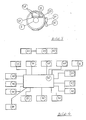
- Figure 3 shows the device for achieving the spin effect.
- the tennis ball (5) will touch the friction roller (27) by centrifugal force.
- This friction roller is driven into the channel by controllable adjusting devices (28).
- the friction roller is connected to an eddy current brake (29).
- the friction roller is connected to a servomotor.
- the friction roller consists of segments with different types of friction coefficients.
- the servomotor rotates the desired friction surface into the departure channel.
- the position of the friction roller can be changed concentrically around the departure channel by means of a servomotor (30) with worm drive (31) and toothed ring (32). This means that spins are possible in any direction and continuously.
- friction systems can be provided concentrically around the departure channel.
- a passive infrared sensor (33) is used for safety reasons. It causes the ball to be blocked when people are in the area of the departure channel.
- a speed sensor (34) measures the speed of the drive wheel and thus enables the ball dropping speed to be determined.
- the departure angle is determined via a further sensor (35).
- the spin (36) applied is also measured (36).
- vibration sensors (37) measure the impact of the ball and thus automatically initiate the next ball sequence.
- the control unit implemented in an embodiment variant (38) by a microcomputer, records the sensor data, processes it and passes it on to the control units motor control main drive (39), motor control spin (strength of the spin and direction) (40), motor control Scatter angle (41). Departure angle (42) and control ball allocation (43) further.
- the computer can communicate with other systems via an interface (44). This can either be another ball throwing machine or a higher-level computer. This allows several ball throwing systems to work in a coordinated manner on a line.
- the computer is coupled to a program memory (45). This means that any type of game can be specified by the program.
- the programs are called up via program keys (46), possibly coupled to a display unit (47).
- the controller receives further data via a receiver (48). This evaluates the signals from the transmitter (49).
- the transmitter works with pulse code modulation. Any address and data combinations are possible. This means that numerous devices can be operated simultaneously. Any program sequences can be called up via buttons, possibly coupled with a display unit (50).
- this transmitter is combined with a ball departure sensor (51). This sensor detects the player's ball throw. The signal is transmitted to the system by radio - the return follows automatically.
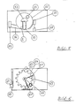
- FIG 5 shows the alternative ball dropping system, which is implemented by a rotating racket (52) instead of a wheel.
- the racket is equipped with counterweights (53) to reduce the tendency to vibrate.
- the racket is coated on the front and back with elastic material. This reduces the impact of the ball being fed.
- the ball is through the opening (54) fed to the system. This opening should preferably be in the middle of the system, since the peripheral speeds are still relatively low there.
- the ball is automatically transported into the outer orbit by centrifugal force.
- the inside of the housing should also be equipped with elastic, damping material with the exception of the outer tread (55).
- the departure channel is represented by (56).
- the take-off angle can be changed relatively easily in this system by rotating the entire acceleration housing with the aid of a ring gear (57) with a servomotor (58).
- the spin-generating system is firmly coupled to the drive housing (59) and is simply rotated with it when the take-off angle changes.
- Figure 6 shows a preferred variant of the ball dropping system.
- the driving wheel is designed in a defined geometry to increase the throwing speed, which increases the coefficient of friction and at the same time ensures that the ball does not receive any spin during the acceleration phase (60).
- the ball is gripped in a defined manner and fixed in its position by the counterpressure of the acceleration rail (61).
- the acceleration rail is guided concentrically around the shafts of the drive wheel and is movably connected to the shaft of the drive wheel via bearings (62) and fastening elements (63). It hangs on the drive shaft like a swing.
- the acceleration rail is segmented. In the area of the ball feed, it is designed to be relatively elastic (64). This can reduce the load on the ball during the start of the acceleration phase.
- the load-bearing structure of the housing is significantly relieved.
- the take-off angle can be changed using an adjusting system consisting of a spindle, motor and fixing devices (65).
- the spin-generating system is driven into the departure channel by the computer, connected to servomotors. (66).
- friction wheels friction surfaces in the form of elastic rubber strips can be used.
- the rubber strips have a different elasticity. This allows the spin effect to be increased or decreased by a defined entry into the departure channel.
- the spin is caused by friction surfaces (72.73), e.g. executed by rubber lips, which are rotated or driven into the departure channel from above or below by servomotors.
- the ball feed in this variant is carried out with the help of a rotating spiral, which is driven by a motor.
- the invention is not limited to the exemplary embodiments shown, but is often variable within the scope of the disclosure.
Landscapes
- Health & Medical Sciences (AREA)
- General Health & Medical Sciences (AREA)
- Physical Education & Sports Medicine (AREA)
- Toys (AREA)
Applications Claiming Priority (1)
| Application Number | Priority Date | Filing Date | Title |
|---|---|---|---|
| DE3914017A DE3914017A1 (de) | 1989-04-28 | 1989-04-28 | Verfahren mit den dazu gehoerigen vorrichtungen zum abwurf von baellen (tennisbaellen, tischtennisbaellen,squash- und fussbaellen) sowie zum erzeugen eines spineffektes in jedweder richtung mit automatisiertem rueckschlag |
Publications (2)
| Publication Number | Publication Date |
|---|---|
| EP0400325A2 true EP0400325A2 (fr) | 1990-12-05 |
| EP0400325A3 EP0400325A3 (fr) | 1991-03-20 |
Family
ID=6379652
Family Applications (1)
| Application Number | Title | Priority Date | Filing Date |
|---|---|---|---|
| EP19900107762 Withdrawn EP0400325A3 (fr) | 1989-04-28 | 1990-04-24 | Procédé et dispositif de lancement de balles et de génération de spins |
Country Status (2)
| Country | Link |
|---|---|
| EP (1) | EP0400325A3 (fr) |
| DE (1) | DE3914017A1 (fr) |
Cited By (7)
| Publication number | Priority date | Publication date | Assignee | Title |
|---|---|---|---|---|
| WO1992011907A1 (fr) * | 1991-01-04 | 1992-07-23 | Werner Salansky | Machine a lancer les balles, en particulier les balles de tennis |
| WO1994011069A1 (fr) * | 1992-11-13 | 1994-05-26 | Robo Sports Technologies Pty. Limited | Machine servant a envoyer des balles |
| RU2139118C1 (ru) * | 1996-07-25 | 1999-10-10 | Печатников Юрий Товьевич | Устройство для тренировки футболиста |
| US9010309B2 (en) | 2011-11-02 | 2015-04-21 | Toca, Llc | Ball throwing machine and method |
| US10118078B2 (en) | 2011-11-02 | 2018-11-06 | Toca Football, Inc. | System, apparatus and method for ball throwing machine and intelligent goal |
| CN114225347A (zh) * | 2021-12-20 | 2022-03-25 | 郑州大学体育学院 | 一种乒乓球自动捡球、发球一体化装置 |
| CN114259719A (zh) * | 2021-11-09 | 2022-04-01 | 蚌埠学院 | 一种用于体育练习的发球装置 |
Families Citing this family (2)
| Publication number | Priority date | Publication date | Assignee | Title |
|---|---|---|---|---|
| WO2006081702A1 (fr) * | 2005-02-04 | 2006-08-10 | Chi Cheung Ng | Appareil de projection de ballons |
| CN114028790B (zh) * | 2021-11-10 | 2023-01-31 | 上海创屹科技有限公司 | 乒乓球发球机器人 |
Family Cites Families (8)
| Publication number | Priority date | Publication date | Assignee | Title |
|---|---|---|---|---|
| DE2438339A1 (de) * | 1974-08-09 | 1976-02-19 | Harald Merkt | Automatisches uebungsgeraet fuer das tischtennisspiel |
| US4168695A (en) * | 1977-10-11 | 1979-09-25 | Rallymaster, Inc. | Portable ball throwing machine having oscillatory feature |
| DE3151886A1 (de) * | 1981-12-30 | 1983-07-07 | Erick Klaus Richter | Wurfmaschine fuer squashbaelle |
| FR2529793A1 (fr) * | 1982-07-08 | 1984-01-13 | Sumsky Kh Poli | Garniture d'orientation pour simulateur lanceur de balles, notamment de tennis ou de football |
| US4705014A (en) * | 1982-07-13 | 1987-11-10 | Kahelin Edward W | Variable speed single-wheeled ball propelling machine |
| FR2563111B1 (fr) * | 1984-04-18 | 1986-08-29 | Leneveu Michel | Dispositif d'alimentation en balles dans un lance-balles integre ou non dans un simulateur de tennis |
| HUT44444A (en) * | 1986-08-11 | 1988-03-28 | Ferenc Kovacs | Automatic programmable tennis-ball serving device controlled by microcomputer |
| US4765618A (en) * | 1987-07-20 | 1988-08-23 | Westphal Daley | Table tennis robot |
-
1989
- 1989-04-28 DE DE3914017A patent/DE3914017A1/de not_active Ceased
-
1990
- 1990-04-24 EP EP19900107762 patent/EP0400325A3/fr not_active Withdrawn
Cited By (15)
| Publication number | Priority date | Publication date | Assignee | Title |
|---|---|---|---|---|
| WO1992011907A1 (fr) * | 1991-01-04 | 1992-07-23 | Werner Salansky | Machine a lancer les balles, en particulier les balles de tennis |
| US5490493A (en) * | 1991-01-04 | 1996-02-13 | Salansky; Werner | Machine for delivering balls, especially tennis balls |
| WO1994011069A1 (fr) * | 1992-11-13 | 1994-05-26 | Robo Sports Technologies Pty. Limited | Machine servant a envoyer des balles |
| AU670549B2 (en) * | 1992-11-13 | 1996-07-25 | Robo Sports Technologies Pty. Limited | Ball propelling machine |
| RU2139118C1 (ru) * | 1996-07-25 | 1999-10-10 | Печатников Юрий Товьевич | Устройство для тренировки футболиста |
| US9555306B2 (en) | 2011-11-02 | 2017-01-31 | Toca Football, Inc. | Ball throwing machine and method |
| US9010309B2 (en) | 2011-11-02 | 2015-04-21 | Toca, Llc | Ball throwing machine and method |
| US10118078B2 (en) | 2011-11-02 | 2018-11-06 | Toca Football, Inc. | System, apparatus and method for ball throwing machine and intelligent goal |
| US10252128B2 (en) | 2011-11-02 | 2019-04-09 | Toca Football, Inc. | Ball throwing machine and method |
| US10744383B2 (en) | 2011-11-02 | 2020-08-18 | Toca Football, Inc. | System, apparatus and method for an intelligent goal |
| US11657906B2 (en) | 2011-11-02 | 2023-05-23 | Toca Football, Inc. | System and method for object tracking in coordination with a ball-throwing machine |
| CN114259719A (zh) * | 2021-11-09 | 2022-04-01 | 蚌埠学院 | 一种用于体育练习的发球装置 |
| CN114259719B (zh) * | 2021-11-09 | 2022-10-25 | 蚌埠学院 | 一种用于体育练习的发球装置 |
| CN114225347A (zh) * | 2021-12-20 | 2022-03-25 | 郑州大学体育学院 | 一种乒乓球自动捡球、发球一体化装置 |
| CN114225347B (zh) * | 2021-12-20 | 2022-09-13 | 郑州大学体育学院 | 一种乒乓球自动捡球、发球一体化装置 |
Also Published As
| Publication number | Publication date |
|---|---|
| EP0400325A3 (fr) | 1991-03-20 |
| DE3914017A1 (de) | 1990-10-31 |
Similar Documents
| Publication | Publication Date | Title |
|---|---|---|
| EP2524636B1 (fr) | Dispositif de préparation de boissons avec dispositif de broyage | |
| EP0400325A2 (fr) | Procédé et dispositif de lancement de balles et de génération de spins | |
| DE2651335C2 (de) | Verfahren und Vorrichtung zum gerichteten Schießen von Fußbällen | |
| US5911214A (en) | Soccer ball projecting apparatus | |
| EP2014372A1 (fr) | Dispositif de dosage pour substances en forme de poudre ou de pâte | |
| DE2434716A1 (de) | Ballwurfgeraet | |
| DE4021282A1 (de) | Verfahren mit den dazu gehoerigen vorrichtungen zum abwurf von baellen (tennisbaellen, tischtennisbaellen, squach- und fussbaellen) sowie zum erzeugen eines spineffektes in jedweder richtung mit automatisiertem rueckschlag | |
| DE60113343T2 (de) | Zuordnungsmechanismus für eine Waage | |
| DE19806898A1 (de) | Gerät zum Lesen und/oder Beschreiben scheibenförmiger Aufzeichnungsträger | |
| DE29907698U1 (de) | An einer Tischtennisplatte anbringbare Ballwurfmaschine für Tischtennis | |
| DE102011105457B4 (de) | Strahlvorrichtung | |
| DE3407972A1 (de) | Programmierbares, automatisches ballspiel-uebungsgeraet | |
| DE2836548A1 (de) | Vorrichtung zur bildung eines rotationssymmetrischen schleiers aus fallenden teilchen | |
| DE19512055C2 (de) | Fernlenkball | |
| DE2438339A1 (de) | Automatisches uebungsgeraet fuer das tischtennisspiel | |
| DE2753120A1 (de) | Tennisball-wurfmaschine | |
| DE2410126A1 (de) | Trainingsgeraet fuer skifahrer, genannt skirotor | |
| EP1163084B1 (fr) | Rectifieuse | |
| DE2710586C2 (de) | Taumelzentrifuge | |
| DE29609598U1 (de) | Ballwerfroboter für Tischtennisbälle | |
| DE2945588A1 (de) | Ballwurfvorrichtung, insbesondere fuer tennisbaelle | |
| CN208302128U (zh) | 一种网球发射装置 | |
| DE112008003885T5 (de) | Bowlingkugel-Oberflächenbehandlungsvorrichtung | |
| DE3046136A1 (de) | Elektromechanisches-magnetisches tischfussball- bzw. tischhockeyspiel | |
| DD150432A5 (de) | Verfahren und anlage zum werfen eines balls |
Legal Events
| Date | Code | Title | Description |
|---|---|---|---|
| PUAI | Public reference made under article 153(3) epc to a published international application that has entered the european phase |
Free format text: ORIGINAL CODE: 0009012 |
|
| AK | Designated contracting states |
Kind code of ref document: A2 Designated state(s): AT BE CH DE DK ES FR GB GR IT LI LU NL SE |
|
| PUAL | Search report despatched |
Free format text: ORIGINAL CODE: 0009013 |
|
| AK | Designated contracting states |
Kind code of ref document: A3 Designated state(s): AT BE CH DE DK ES FR GB GR IT LI LU NL SE |
|
| STAA | Information on the status of an ep patent application or granted ep patent |
Free format text: STATUS: THE APPLICATION IS DEEMED TO BE WITHDRAWN |
|
| 18D | Application deemed to be withdrawn |
Effective date: 19910921 |