EP0400489A2 - Système de localisation, en particulier pour l'exploitation au fond - Google Patents
Système de localisation, en particulier pour l'exploitation au fond Download PDFInfo
- Publication number
- EP0400489A2 EP0400489A2 EP90109919A EP90109919A EP0400489A2 EP 0400489 A2 EP0400489 A2 EP 0400489A2 EP 90109919 A EP90109919 A EP 90109919A EP 90109919 A EP90109919 A EP 90109919A EP 0400489 A2 EP0400489 A2 EP 0400489A2
- Authority
- EP
- European Patent Office
- Prior art keywords
- transmitter
- location
- remote control
- location system
- switched
- Prior art date
- Legal status (The legal status is an assumption and is not a legal conclusion. Google has not performed a legal analysis and makes no representation as to the accuracy of the status listed.)
- Withdrawn
Links
- 230000006870 function Effects 0.000 claims description 38
- 230000005540 biological transmission Effects 0.000 claims description 32
- 238000005065 mining Methods 0.000 claims description 9
- 229910000859 α-Fe Inorganic materials 0.000 claims description 7
- 238000005516 engineering process Methods 0.000 claims description 5
- 230000003287 optical effect Effects 0.000 claims description 2
- 238000010586 diagram Methods 0.000 description 5
- 238000013459 approach Methods 0.000 description 2
- 238000013461 design Methods 0.000 description 2
- 238000005265 energy consumption Methods 0.000 description 2
- 238000011156 evaluation Methods 0.000 description 2
- 238000001208 nuclear magnetic resonance pulse sequence Methods 0.000 description 2
- 239000003381 stabilizer Substances 0.000 description 2
- 208000003443 Unconsciousness Diseases 0.000 description 1
- 230000004913 activation Effects 0.000 description 1
- 230000001419 dependent effect Effects 0.000 description 1
- 230000000694 effects Effects 0.000 description 1
- 238000004880 explosion Methods 0.000 description 1
- 238000005259 measurement Methods 0.000 description 1
- 238000000034 method Methods 0.000 description 1
- 230000001105 regulatory effect Effects 0.000 description 1
- 230000000717 retained effect Effects 0.000 description 1
Images


Classifications
-
- A—HUMAN NECESSITIES
- A62—LIFE-SAVING; FIRE-FIGHTING
- A62B—DEVICES, APPARATUS OR METHODS FOR LIFE-SAVING
- A62B99/00—Subject matter not provided for in other groups of this subclass
-
- A—HUMAN NECESSITIES
- A63—SPORTS; GAMES; AMUSEMENTS
- A63B—APPARATUS FOR PHYSICAL TRAINING, GYMNASTICS, SWIMMING, CLIMBING, OR FENCING; BALL GAMES; TRAINING EQUIPMENT
- A63B29/00—Apparatus for mountaineering
- A63B29/02—Mountain guy-ropes or accessories, e.g. avalanche ropes; Means for indicating the location of accidentally buried, e.g. snow-buried, persons
- A63B29/021—Means for indicating the location of accidentally buried, e.g. snow-buried, persons
-
- F—MECHANICAL ENGINEERING; LIGHTING; HEATING; WEAPONS; BLASTING
- F16—ENGINEERING ELEMENTS AND UNITS; GENERAL MEASURES FOR PRODUCING AND MAINTAINING EFFECTIVE FUNCTIONING OF MACHINES OR INSTALLATIONS; THERMAL INSULATION IN GENERAL
- F16P—SAFETY DEVICES IN GENERAL; SAFETY DEVICES FOR PRESSES
- F16P3/00—Safety devices acting in conjunction with the control or operation of a machine; Control arrangements requiring the simultaneous use of two or more parts of the body
- F16P3/12—Safety devices acting in conjunction with the control or operation of a machine; Control arrangements requiring the simultaneous use of two or more parts of the body with means, e.g. feelers, which in case of the presence of a body part of a person in or near the danger zone influence the control or operation of the machine
- F16P3/14—Safety devices acting in conjunction with the control or operation of a machine; Control arrangements requiring the simultaneous use of two or more parts of the body with means, e.g. feelers, which in case of the presence of a body part of a person in or near the danger zone influence the control or operation of the machine the means being photocells or other devices sensitive without mechanical contact
- F16P3/147—Safety devices acting in conjunction with the control or operation of a machine; Control arrangements requiring the simultaneous use of two or more parts of the body with means, e.g. feelers, which in case of the presence of a body part of a person in or near the danger zone influence the control or operation of the machine the means being photocells or other devices sensitive without mechanical contact using electro-magnetic technology, e.g. tags or radar
-
- G—PHYSICS
- G01—MEASURING; TESTING
- G01S—RADIO DIRECTION-FINDING; RADIO NAVIGATION; DETERMINING DISTANCE OR VELOCITY BY USE OF RADIO WAVES; LOCATING OR PRESENCE-DETECTING BY USE OF THE REFLECTION OR RERADIATION OF RADIO WAVES; ANALOGOUS ARRANGEMENTS USING OTHER WAVES
- G01S13/00—Systems using the reflection or reradiation of radio waves, e.g. radar systems; Analogous systems using reflection or reradiation of waves whose nature or wavelength is irrelevant or unspecified
- G01S13/74—Systems using reradiation of radio waves, e.g. secondary radar systems; Analogous systems
- G01S13/76—Systems using reradiation of radio waves, e.g. secondary radar systems; Analogous systems wherein pulse-type signals are transmitted
- G01S13/767—Responders; Transponders
Definitions
- the invention relates to a location system, in particular for underground mining, with a location transmitter to be carried by a person to be located and a location receiver to be carried by a searching person or the like, electromagnetic waves emitted by the location transmitter being received by the location receiver and evaluated in terms of location technology, the location transmitter can be switched on if necessary and can also be switched off again at the appropriate time.
- the location system known from practice, from which the invention is based, is intended for underground mining and initially has a location transmitter carried by a person to be located, namely there, for example, built into the housing of the headlamp accumulator.
- the location transmitter emits electromagnetic waves of a certain frequency, preferably a frequency specific to the particular location transmitter.
- the locating transmitter generally only does this if it has been switched on manually or is automatically switched on in the event of a fall in the person wearing the locating transmitter or in the event of an explosion with a certain pressure threshold being exceeded.
- the electromagnetic waves emitted by the location transmitter can also be encoded in the form of pulse sequences, so that it is possible to keep a large number of location transmitters distinguishable from one another.
- Normal equipment details of the known location transmitter are batteries and / or accumulators and an overall intrinsically safe version.
- the locating receiver of the known locating system is designed as a portable device and can be worn, for example, by a mine rescuer on a carrying strap around the neck or over the shoulder.
- the locating receiver is also expediently designed to be intrinsically safe and has a corresponding antenna suitable as a direction finding antenna. By trigonometric two-point location or by gradient location, the distance of a location transmitter can also be determined in addition to the direction.
- the previously described, previously known location system is not yet safe enough, since the location transmitter is often not switched on in the event of an accident or, when it is switched on, its battery or accumulator is exhausted after a relatively short time, so that the switch on itself
- the location transmitter does not emit a location signal when the mine rescuers finally begin to approach the scene of the accident.
- the location system should be able to be used even more flexibly.
- the invention is therefore based on the object of specifying a location system of the type in question, which can be used even more reliably and flexibly compared to the prior art.
- a remote control transmitter is additionally provided, that the location transmitter is also designed as a receiver for electromagnetic waves emitted by the remote control transmitter, that the location transmitter is in the idle state in reception function and only when receiving from the remote control transmitter electromagnetic waves the transmission function is switched on.
- an additional system element is therefore used in the location system, namely the remote control transmitter, which is used to activate the location transmitter of the person to be located in the first place when necessary, that is to say to switch it to the transmission function.
- the location transmitter itself is also designed as a receiver, so that it can receive the electromagnetic waves emitted by the remote control transmitter, which can also be encoded again in the manner explained above.
- the transmission function is switched on, so that the locating receiver carried by the mine rescuer, for example, can receive the electromagnetic waves transmitted by the locating transmitter. It is thereby achieved that the location transmitter is always actually switched on when this is necessary, namely when, for example, people who are buried are searched for using a corresponding remote control transmitter. This happens regardless of an activity of the Or person carrying the transmitter, even if this is, for example, unconscious, the location transmitter is switched on safely. However, the location transmitter is only switched on if this makes sense in terms of location technology, namely only if a location receiver is nearby.
- the range of the remote control transmitter is of course to be roughly matched to the range of the location transmitter. In this way, it is ensured that the location transmitter does not work senselessly while consuming the valuable electrical energy from the battery, but only works when and only if it makes sense in terms of location.
- the respectively emitted electromagnetic waves should be coded in a certain form, for example limited to certain carrier frequencies and / or coded to certain pulse trains.
- the location system according to the invention shows the basic structure of the location system according to the invention, which is particularly suitable for use in underground mining, for example for locating and rescuing buried miners.
- the location system according to the invention can also be used elsewhere, for example in avalanche location or the like.
- the positioning system according to the invention can also be used in the context of personal protection systems, for example to provide automatic shutdown at certain points in conveyor belts for people, to trigger a safety shutdown in the area of work machines when people approach, etc.
- the locating system shown schematically in FIG. 1 initially has a locating transmitter 1 to be carried by a person to be located and a locating receiver 2 to be carried by a searching person or the like or else arranged or transported in another way.
- electromagnetic waves emitted by the location transmitter 1 are received by the location receiver 2 and evaluated by the location receiver. This can be done with the aid of analog displays 3, acoustic detectors 4, digital displays 5 and with various other evaluation techniques. If necessary, the locating transmitter 1 can be switched on and, of course, can also be switched off again at the appropriate time.
- the main idea of the invention is that, in addition to the locating transmitter 1 and the locating receiver 2, there is a third system part, namely a remote control transmitter 6.
- the locating transmitter 1 is also a receiver for electromagnetic waves transmitted by the remote control transmitter 6, likewise again with a specific frequency or encoded in a certain form, executed.
- the locating transmitter 1 In the idle state, the locating transmitter 1 is in the receiving function, in which it transmits the capable of receiving electromagnetic waves emitted by the remote control transmitter 6.
- the locating transmitter 1 is switched to the transmitting function only when electromagnetic waves emitted by the remote control transmitter 6 are received. Only then is the locating transmitter 1 emitting the electromagnetic waves required for locating, only then does the high energy consumption associated with the transmitting function of the locating transmitter 1 occur.
- the locating transmitter 1 thus always works in this way, but only if this makes sense in terms of location technology, irrespective of handling by the person to be located.
- the location transmitter 1 requires only little energy to receive the electromagnetic waves emitted by the remote control transmitter 6. It is therefore advisable to design the locating transmitter 1 in such a way that it only requires a minimum operating current of preferably only a few ⁇ A in the receive function.
- the range of the remote control transmitter 6 provided according to the invention should be matched to the range of the location transmitter 1 designed according to the invention as a receiver and transmitter.
- the range naturally also has something to do with the ambient conditions, in particular the electromagnetic interference from other devices, so that there is a certain fluctuation range here.
- a range of the remote control transmitter 6 of ⁇ 25 m with disruptive devices switched off and a range of ⁇ 20 m for the locating transmitter 1 can also be switched off with disruptive devices for the area of underground mining.
- the location transmitter 1 automatically switch off the transmission function again after a certain, predetermined period of time after the transmission function has been switched on.
- the switch-on time of the transmission function depends of course on the respective application. Turn-on times between 3 and 50 minutes, preferably between 15 and 30 minutes, have proven to be useful for underground mining.
- the location transmitter 1 of the invention it is advisable to configure the location transmitter 1 of the invention to be switched off by hand, and if necessary also to be switched on by hand. However, care must be taken to ensure that the location transmitter 1 cannot be switched on or off accidentally in order not to endanger the advantages achieved according to the invention.
- the locating transmitter 1 cannot be switched on accidentally by electromagnetic interference fields present in underground mining, so that it is designed to be largely immune to interference.
- the coding measures explained at the beginning are recommended.
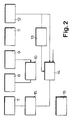
- the block diagram shown in FIG. 2 of the locating transmitter 1 used in the locating system according to the invention shows a transmitting and receiving antenna 7, for example a ferrite antenna or a dipole antenna, and a selective amplifier 8 connected downstream of the transmitting and receiving antenna 7 for the intended remote switching frequency.
- the selective amplifier 8 is followed by a detector transformer 9, both of which in turn are fed back via an automatic gain control 10.
- a pulse shaper 11 is connected downstream of the detector transformer 9, which in turn is followed by a pulse train detector 12 in terms of circuitry.
- a timer 13 for specifying the switch-on time in the transmit function, and on the other hand, a status memory 14 is connected.
- the timer 13 is connected on the output side to the state memory 14.
- the state memory 14 is finally followed by a transmission pulse generator 15 connected on the output side to the transmitting and receiving antenna 7.
- the battery 16 provided for the intrinsically safe voltage supply of the locating transmitter 1 is also shown.
- the remote switching frequency emitted by the remote control transmitter 6 is received via the transmitting and receiving antenna 7.
- the received signals are forwarded to the selective amplifier 8, which amplifies only those with the intended frequency.
- the gain is regulated depending on the control signal of the automatic gain control 10.
- the carrier frequency signals are transformed into direct current pulses, specifically at a certain desired signal level.
- the distorted pulses of the pulse train from the detector transformer 9 are transformed into rectangular pulses which are optimal in terms of evaluation technology.
- the pulse train detector 12 recognizes the correctly coded pulse train. If the correct pulse train arrives, the state memory 14 is switched to the active state, which corresponds to the activation of the transmission function.
- the timer 13 switches the state memory 14 back after the predetermined switch-on time of the transmission function, so that the transmission function is switched off.
- the state memory 14 controls in the transmission function the transmission pulse generator 15, which then outputs the locating frequency, which is preferably a different frequency than the remote switching frequency, via the transmission and reception antenna 7.
- An arrow on the state memory 14 also indicates the external possibility to be specified by hand for resetting the state memory 14, that is to say for switching off the transmission function.
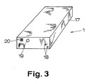
- FIG. 3 clearly shows the external structure of an example of a location transmitter 1 of the type in question.
- a housing 17 is shown which should meet the requirements with regard to pressure resistance and impact resistance, which are also made of mine lamps and mine accumulators. Nevertheless, this housing 17 should be as light as possible so that the locating transmitter 1 can be carried easily.
- the location transmitter 1 can be switched off, that is to say switched off from the transmission function, by electrically short-circuiting the switch-off contacts 18 with any electrically conductive object. This is a very simple solution, but it has proven itself in practice, since accidental incorrect operation is extremely rare.
- Fig. 3 shows further in the housing 17, an optical function display 19, here in the form of a light emitting diode.
- the housing also shows two ground contacts 20 of the battery 16.
- the remote control transmitter 6 shown in FIG. 1 and shown in more detail in a block diagram in FIG. 4 should likewise be designed as a portable device, in particular thus be easily portable by a searching person, for example a mine rescuer.
- the remote control transmitter 6 expediently has a long range and, accordingly, a high transmission power.
- the remote control transmitter 6 has a folding dipole antenna for long distances, in particular distances of 20 m and more, and / or a ferrite antenna (shown in FIG. 1) for shorter distances, in particular distances up to 6 m.
- the transmitting antenna for example the ferrite antenna 21 of the remote control transmitter 6
- the transmitting antenna has a direction-dependent characteristic
- the remote control transmitter 6 has a short range, in particular a range of less than 4 m, and accordingly has a low transmission power.
- a short range in particular a range of less than 4 m, and accordingly has a low transmission power.
- Such a system is suitable, for example, as part of a security system for people on a passenger conveyor belt or the like.
- the remote control transmitter 6 is assigned an alarm receiver.
- the remote control transmitter 6 thus equipped with low power and the alarm receiver, if any, are stationary devices that are permanently attached to selected locations, for example in underground mining, and are activated or activated by an approaching person who is wearing a corresponding location transmitter 1. Activate the location transmitter 1 yourself beforehand.
- the remote control transmitter 6 has a pulse train generator 22, a tunable carrier frequency oscillator 23, a gate circuit 24, an output amplifier 25, an antenna tuner 26 and the antenna already mentioned above, for example a ferrite antenna 21. Also shown are a voltage stabilizer 27, a battery as voltage supply 28 and a current measuring circuit 29 with the possibility of an analog measurement 30 and a digital light display 31, with the aid of which the antenna 21 can be optimally tuned.
- the carrier frequency oscillator 23 can be swept through the entire transmission frequency range. This can be done at different speeds, tailored to the application.
- the pulse train generator 22 of the remote control transmitter 6 shown in FIG. 4 can work, for example, in a 1:15 cycle, with a pulse sequence in the first cycle and 15 pause cycles.
- the carrier frequency oscillator 23 generates the carrier frequency. It can be wobbled in the transmission frequency range.
- the gate circuit 24 enables the passage of the carrier frequency in the ranges predetermined by the pulse train generator 22.
- the pulses emitted by the gate circuit 24 are amplified in the output amplifier 25.
- the antenna circuit 26 can be used to tune the output circuit to the antenna types which can be switched on differently - folded dipole antenna, ferrite antenna or the like.
- the tuning control is made possible by the circuit 29, 30, 31.
- the voltage stabilizer 27 stabilizes the supply voltage in order to eliminate interference from this side.
Landscapes
- Engineering & Computer Science (AREA)
- Radar, Positioning & Navigation (AREA)
- Remote Sensing (AREA)
- Health & Medical Sciences (AREA)
- General Engineering & Computer Science (AREA)
- General Health & Medical Sciences (AREA)
- Physics & Mathematics (AREA)
- General Physics & Mathematics (AREA)
- Business, Economics & Management (AREA)
- Emergency Management (AREA)
- Pulmonology (AREA)
- Physical Education & Sports Medicine (AREA)
- Computer Networks & Wireless Communication (AREA)
- Mechanical Engineering (AREA)
- Radar Systems Or Details Thereof (AREA)
- Selective Calling Equipment (AREA)
Applications Claiming Priority (2)
| Application Number | Priority Date | Filing Date | Title |
|---|---|---|---|
| DE3917996 | 1989-06-02 | ||
| DE3917996 | 1989-06-02 |
Publications (2)
| Publication Number | Publication Date |
|---|---|
| EP0400489A2 true EP0400489A2 (fr) | 1990-12-05 |
| EP0400489A3 EP0400489A3 (fr) | 1991-10-23 |
Family
ID=6381914
Family Applications (1)
| Application Number | Title | Priority Date | Filing Date |
|---|---|---|---|
| EP19900109919 Withdrawn EP0400489A3 (fr) | 1989-06-02 | 1990-05-25 | Système de localisation, en particulier pour l'exploitation au fond |
Country Status (2)
| Country | Link |
|---|---|
| EP (1) | EP0400489A3 (fr) |
| CA (1) | CA2018109A1 (fr) |
Cited By (3)
| Publication number | Priority date | Publication date | Assignee | Title |
|---|---|---|---|---|
| NL9301542A (nl) * | 1993-09-06 | 1995-04-03 | Nedap Nv | Beveiliging voor handbediende electrische of electro-mechanische apparaten. |
| WO2006065219A1 (fr) * | 2004-12-13 | 2006-06-22 | Fredrik Carle | Dispositif de sauvetage portable et son procede de localisation |
| RU2482896C1 (ru) * | 2011-12-20 | 2013-05-27 | Открытое акционерное общество "Авангард" | Способ обнаружения местонахождения засыпанных биообъектов или их останков и устройство для его осуществления |
Family Cites Families (4)
| Publication number | Priority date | Publication date | Assignee | Title |
|---|---|---|---|---|
| DE3123557A1 (de) * | 1981-06-13 | 1983-03-03 | Bergwerksverband Gmbh, 4300 Essen | Markierungsschutzguertel |
| US4495496A (en) * | 1981-12-15 | 1985-01-22 | Johnson Engineering Corp. | Personnel monitoring and locating system |
| HUT43774A (en) * | 1986-05-15 | 1987-11-30 | Koezponti Banyaszati Fejleszte | Method and apparatus for automatic identification living beings and objects |
| DE3643236A1 (de) * | 1986-12-18 | 1988-07-07 | Ruhrkohle Ag | Personenschutzfunkgeraet |
-
1990
- 1990-05-25 EP EP19900109919 patent/EP0400489A3/fr not_active Withdrawn
- 1990-06-01 CA CA002018109A patent/CA2018109A1/fr not_active Abandoned
Cited By (4)
| Publication number | Priority date | Publication date | Assignee | Title |
|---|---|---|---|---|
| NL9301542A (nl) * | 1993-09-06 | 1995-04-03 | Nedap Nv | Beveiliging voor handbediende electrische of electro-mechanische apparaten. |
| WO2006065219A1 (fr) * | 2004-12-13 | 2006-06-22 | Fredrik Carle | Dispositif de sauvetage portable et son procede de localisation |
| US7245899B2 (en) | 2004-12-13 | 2007-07-17 | Fredrik Carle | Portable rescue device and a method for locating such a device |
| RU2482896C1 (ru) * | 2011-12-20 | 2013-05-27 | Открытое акционерное общество "Авангард" | Способ обнаружения местонахождения засыпанных биообъектов или их останков и устройство для его осуществления |
Also Published As
| Publication number | Publication date |
|---|---|
| CA2018109A1 (fr) | 1990-12-02 |
| EP0400489A3 (fr) | 1991-10-23 |
Similar Documents
| Publication | Publication Date | Title |
|---|---|---|
| DE3643236C2 (fr) | ||
| EP0733916A2 (fr) | Dispositif de recherche portatif | |
| DE10201505B4 (de) | Arbeitsschutzvorrichtung für Bergleute | |
| DE3100638A1 (de) | Einbruchs- und diebstahlsicherung bei fahrzeugen | |
| DE2918531A1 (de) | Elektronische uhr, insbesondere armbanduhr, mit alarmvorrichtung | |
| DE3209662A1 (de) | Generator fuer die erzeugung von radiosignalfolgen und tragbarer sender, der einen solchen generator einschliesst | |
| DE4016959A1 (de) | Ortungssystem, insbesondere fuer den untertaegigen bergbau | |
| DE3407345A1 (de) | Ueberwachungsanordnung | |
| DE2424278B2 (de) | Mit elektromagnetischer Strahlung arbeitende Überwachungsanlage | |
| EP0400489A2 (fr) | Système de localisation, en particulier pour l'exploitation au fond | |
| EP3278311A1 (fr) | Système de surveillance d'un dispositif fonctionnant au moyen d'une batterie | |
| DE4010327C1 (fr) | ||
| DE3230556A1 (de) | Lichtschrankenobjektaussensicherungsvorrichtung | |
| DE4041825C2 (de) | Alarmanlage | |
| DE2436225A1 (de) | Sicherheitsalarmvorrichtung | |
| DE3442586C2 (fr) | ||
| DE2820840A1 (de) | System zur absicherung von gefahrenbereichen in untertagebetrieben | |
| DE2517453C3 (de) | Meldevorrichtung | |
| DE19707560A1 (de) | Vorrichtung zur Erkennung von betriebsbereiten mobilen Telefonapparaten | |
| DE3004411A1 (de) | Verfahren und vorrichtung zur sicherung gefaehrdeter personen | |
| DE2425332C2 (de) | Anordnung zur Absicherung von Gefahrenbereichen In Untertagebetrieben | |
| DE2256926B2 (de) | Raumüberwachungseinrichtung | |
| DE2607226C3 (de) | Schalteinrichtung zum berührungslosen Schalten von am Strebförderer geführten Kohlenhobeln | |
| DE10219777A1 (de) | Vorrichtung zum Betrieb eines Wildzauns oder dergleichen | |
| DE2625017A1 (de) | Einrichtung zur sicherung und auffindung von einem oder mehreren objekten |
Legal Events
| Date | Code | Title | Description |
|---|---|---|---|
| PUAI | Public reference made under article 153(3) epc to a published international application that has entered the european phase |
Free format text: ORIGINAL CODE: 0009012 |
|
| AK | Designated contracting states |
Kind code of ref document: A2 Designated state(s): AT CH DE FR GB IT LI SE |
|
| 17P | Request for examination filed |
Effective date: 19901220 |
|
| PUAL | Search report despatched |
Free format text: ORIGINAL CODE: 0009013 |
|
| AK | Designated contracting states |
Kind code of ref document: A3 Designated state(s): AT CH DE FR GB IT LI SE |
|
| 17Q | First examination report despatched |
Effective date: 19940505 |
|
| STAA | Information on the status of an ep patent application or granted ep patent |
Free format text: STATUS: THE APPLICATION IS DEEMED TO BE WITHDRAWN |
|
| 18D | Application deemed to be withdrawn |
Effective date: 19940916 |