EP0400535A2 - Dispositif d'attache - Google Patents
Dispositif d'attache Download PDFInfo
- Publication number
- EP0400535A2 EP0400535A2 EP90110077A EP90110077A EP0400535A2 EP 0400535 A2 EP0400535 A2 EP 0400535A2 EP 90110077 A EP90110077 A EP 90110077A EP 90110077 A EP90110077 A EP 90110077A EP 0400535 A2 EP0400535 A2 EP 0400535A2
- Authority
- EP
- European Patent Office
- Prior art keywords
- dowel
- screw
- fastening element
- anchoring
- element according
- Prior art date
- Legal status (The legal status is an assumption and is not a legal conclusion. Google has not performed a legal analysis and makes no representation as to the accuracy of the status listed.)
- Granted
Links
Images


Classifications
-
- F—MECHANICAL ENGINEERING; LIGHTING; HEATING; WEAPONS; BLASTING
- F16—ENGINEERING ELEMENTS AND UNITS; GENERAL MEASURES FOR PRODUCING AND MAINTAINING EFFECTIVE FUNCTIONING OF MACHINES OR INSTALLATIONS; THERMAL INSULATION IN GENERAL
- F16B—DEVICES FOR FASTENING OR SECURING CONSTRUCTIONAL ELEMENTS OR MACHINE PARTS TOGETHER, e.g. NAILS, BOLTS, CIRCLIPS, CLAMPS, CLIPS OR WEDGES; JOINTS OR JOINTING
- F16B35/00—Screw-bolts; Stay-bolts; Screw-threaded studs; Screws; Set screws
- F16B35/04—Screw-bolts; Stay-bolts; Screw-threaded studs; Screws; Set screws with specially-shaped head or shaft in order to fix the bolt on or in an object
- F16B35/041—Specially-shaped shafts
-
- E—FIXED CONSTRUCTIONS
- E06—DOORS, WINDOWS, SHUTTERS, OR ROLLER BLINDS IN GENERAL; LADDERS
- E06B—FIXED OR MOVABLE CLOSURES FOR OPENINGS IN BUILDINGS, VEHICLES, FENCES OR LIKE ENCLOSURES IN GENERAL, e.g. DOORS, WINDOWS, BLINDS, GATES
- E06B1/00—Border constructions of openings in walls, floors, or ceilings; Frames to be rigidly mounted in such openings
- E06B1/56—Fastening frames to the border of openings or to similar contiguous frames
- E06B1/60—Fastening frames to the border of openings or to similar contiguous frames by mechanical means, e.g. anchoring means
-
- F—MECHANICAL ENGINEERING; LIGHTING; HEATING; WEAPONS; BLASTING
- F16—ENGINEERING ELEMENTS AND UNITS; GENERAL MEASURES FOR PRODUCING AND MAINTAINING EFFECTIVE FUNCTIONING OF MACHINES OR INSTALLATIONS; THERMAL INSULATION IN GENERAL
- F16B—DEVICES FOR FASTENING OR SECURING CONSTRUCTIONAL ELEMENTS OR MACHINE PARTS TOGETHER, e.g. NAILS, BOLTS, CIRCLIPS, CLAMPS, CLIPS OR WEDGES; JOINTS OR JOINTING
- F16B13/00—Dowels or other devices fastened in walls or the like by inserting them in holes made therein for that purpose
- F16B13/12—Separate metal or non-separate or non-metal dowel sleeves fastened by inserting the screw, nail or the like
- F16B13/124—Separate metal or non-separate or non-metal dowel sleeves fastened by inserting the screw, nail or the like fastened by inserting a threaded element, e.g. screw or bolt
-
- F—MECHANICAL ENGINEERING; LIGHTING; HEATING; WEAPONS; BLASTING
- F16—ENGINEERING ELEMENTS AND UNITS; GENERAL MEASURES FOR PRODUCING AND MAINTAINING EFFECTIVE FUNCTIONING OF MACHINES OR INSTALLATIONS; THERMAL INSULATION IN GENERAL
- F16B—DEVICES FOR FASTENING OR SECURING CONSTRUCTIONAL ELEMENTS OR MACHINE PARTS TOGETHER, e.g. NAILS, BOLTS, CIRCLIPS, CLAMPS, CLIPS OR WEDGES; JOINTS OR JOINTING
- F16B33/00—Features common to bolt and nut
- F16B33/02—Shape of thread; Special thread-forms
-
- F—MECHANICAL ENGINEERING; LIGHTING; HEATING; WEAPONS; BLASTING
- F16—ENGINEERING ELEMENTS AND UNITS; GENERAL MEASURES FOR PRODUCING AND MAINTAINING EFFECTIVE FUNCTIONING OF MACHINES OR INSTALLATIONS; THERMAL INSULATION IN GENERAL
- F16B—DEVICES FOR FASTENING OR SECURING CONSTRUCTIONAL ELEMENTS OR MACHINE PARTS TOGETHER, e.g. NAILS, BOLTS, CIRCLIPS, CLAMPS, CLIPS OR WEDGES; JOINTS OR JOINTING
- F16B5/00—Joining sheets or plates, e.g. panels, to one another or to strips or bars parallel to them
- F16B5/02—Joining sheets or plates, e.g. panels, to one another or to strips or bars parallel to them by means of fastening members using screw-thread
- F16B5/0275—Joining sheets or plates, e.g. panels, to one another or to strips or bars parallel to them by means of fastening members using screw-thread the screw-threaded element having at least two axially separated threaded portions
-
- F—MECHANICAL ENGINEERING; LIGHTING; HEATING; WEAPONS; BLASTING
- F16—ENGINEERING ELEMENTS AND UNITS; GENERAL MEASURES FOR PRODUCING AND MAINTAINING EFFECTIVE FUNCTIONING OF MACHINES OR INSTALLATIONS; THERMAL INSULATION IN GENERAL
- F16B—DEVICES FOR FASTENING OR SECURING CONSTRUCTIONAL ELEMENTS OR MACHINE PARTS TOGETHER, e.g. NAILS, BOLTS, CIRCLIPS, CLAMPS, CLIPS OR WEDGES; JOINTS OR JOINTING
- F16B25/00—Screws that cut thread in the body into which they are screwed, e.g. wood screws
- F16B25/10—Screws performing an additional function to thread-forming, e.g. drill screws or self-piercing screws
- F16B25/106—Screws performing an additional function to thread-forming, e.g. drill screws or self-piercing screws by means of a self-piercing screw-point, i.e. without removing material
Definitions
- the invention relates to a fastening element for mounting profiles, frames, plates or the like.
- a fastening element for mounting profiles, frames, plates or the like.
- the screw On a fixed substructure by means of screws and anchoring dowels, the screw being provided with a thread extending over the entire length of the shaft.
- Such fasteners are used for direct or spaced fastening of profiles, frames, plates or the like, for example on masonry or an underlying solid substructure made of wood, bricks, metal or the like. It is already a spacer screw with a recess for Inserting a tool has become known, which has a shorter, thicker threaded part on the tool side and a partially threaded, thinner part at its free end. At the transition between these two different thick thread parts, a clamping groove with a cutting edge must be provided in order to reduce the material-displacing effect of the thicker thread part. Such a design is particularly suitable for fastening wooden profiles to a fixed substructure. If, on the other hand, metal profiles are to be fastened with relatively thin webs, then the thread of the thicker section of the screw is usually not sufficient to ensure secure fastening.
- a fastening element consisting of an anchoring plug and a screw is provided, the screw being provided with a thread extending over the entire length of the shaft.
- a screw combination is also known (DE-OS 33 10 321), which is used to screw objects together.
- This screw combination consists of a shaft part and a nut part, with the spaced assembly the objects of this distance can be changed within limits after assembly by turning the shaft part or the nut part when the other part is at a standstill.
- a nut part which acts like a dowel, an anchoring plug and also a screw part, three parts are required, which have considerable differences in diameter.
- a first threaded section is formed at the free end of the shaft for screwing into an anchoring plug and a second threaded section near the screw head with a larger outside diameter than the first threaded section is provided.
- the two thread sections have different thread pitches.
- the present invention has therefore set itself the task of creating a fastening element which is suitable for direct or spaced fastening of profiles, frames, plates or the like. All designs and materials, whether they are solid or hollow bodies.
- a first threaded section is formed on the free end of the shaft for screwing into an anchoring plug and a second threaded section near the screw head is provided with a larger outside diameter than the first threaded section and both threaded sections have the same thread pitch that one in the installed position of the fastening element in the profile to be fastened, the frame, the plate or the like, which engages and can be brought into operative connection with the screw section near the screw head in the connection process has approximately constant outer diameter.
- a dowel sleeve is also provided, which enables the necessary firm fit within the profiles, frames, plates or the like to be fastened.
- the correspondingly larger diameter of the threaded section near the screw head ensures that the profiles, frames, plates or the like to be fastened are securely held in the same even with a corresponding number of cavities, since the material of the dowel sleeve penetrates relatively far into the hollow chambers or recesses of profiles Especially since the relatively large diameter of the screw section near the screw head causes the material of the dowel sleeve to be pushed apart further.
- the fastening element according to the invention provides sufficient support both when fastening in a solid profile and when fastening hollow profiles, since the penetrating thread causes the dowel sleeve to be displaced outwards and thus causes pressure on the bore wall or even on the profile webs.
- the free inside diameter of the dowel sleeve corresponds approximately to the outside diameter of the threaded section facing the free end of the shaft of the screw.
- the screw with its first threaded section can thus be inserted directly through the dowel sleeve, so that no rotary movement is required here.
- the dowel sleeve has a longitudinal slot which extends over at least approximately its entire length and which is open at the free end of the dowel sleeve or closed by a tear-off or breakable web.
- This longitudinal slot makes it possible for the dowel sleeve to expand well when the second threaded section with the relatively large diameter is screwed in, without the dowels sleeve may be torn uncontrollably. It is therefore always possible to properly engage in the profile to be fastened or the like.
- a plane through the longitudinal slot is at a distance from the center axis of the dowel.
- corresponding slots can only be created by laterally insertable and retractable molded parts. It has proven to be expedient if these insertable parts do not lie directly in a radial plane with the object to be manufactured.
- the anchoring dowel and the dowel sleeve have an external profile in the form of sawtooth-like ribs. This enables a secure hold in the steel inserts provided for example in plastic window profiles, so that there is practically a positive anchoring after the screws have been screwed in.
- the anchoring dowel and the dowel sleeve should be able to absorb forces in the opposite direction, that is, the anchoring dowel should not be able to be pulled out of the bore in the fixed substructure and, on the other hand, the profile or the like to be fastened should not be removed from the solid base be removable, so the dowel sleeve must not be able to be pulled out at the back of the profile.
- This mutually directed arrangement of the sawtooth-like ribs has a particularly advantageous effect here.
- the sawtooth-like ribs on the dowel sleeve are formed by two or more rib sections offset axially to one another, each of which extends over a partial region of the circumference of the dowel sleeve. This guarantees that any depth of use can be secured in one Corresponding ribs or the like are available, which can snap into adjacent depressions or elevations in a profile or the like or below or above a steel insert inserted into the profile.
- the inner longitudinal recess of the anchoring dowel has a plurality of longitudinal ribs distributed around the circumference with grooves remaining therebetween. It is therefore ensured that the thread flanks are pressed in securely on the inside of the anchoring dowel and also that the anchoring dowel is pressed radially against the bore wall.
- the anchoring dowel have freely projecting, wing-like webs oriented in an approximately radial direction, but at an acute angle to its longitudinal axis.
- the arrangement of these webs makes it possible to simply push the dowel into the hole in the solid surface, but these wing-like webs prevent the dowel from twisting when the screw is screwed in, as long as the pressing force of the anchoring dowel on the wall of the hole is not yet sufficient.
- the anchoring dowel have axial slots guided over the respective area of a wing-like web.
- An expedient embodiment is that two pairs of wing-like webs which follow one another in the axial direction are provided on the end of the anchoring dowel facing the dowel sleeve and one or two pairs of slot sections with an angular orientation with respect to the central axis of the dowel at the free end region of the anchoring dowel are trained. It is therefore an optimal combination of the anchoring anchor's security against rotation and the possibility of sufficient expansion possible in the hole so that the dowel is properly seated after the screw has been screwed in.
- a particularly advantageous embodiment is when the screw head has at least approximately the same outside diameter as the dowel. This measure also allows the screw head to be recessed in a profile to be fastened, so it does not form a disturbing factor on the surface of the profile and, in addition, only a hole of the same diameter is necessary, since dowels and screws can be inserted through the uniformly large hole.
- the cross section of the screw blank in the threaded section near the screw head is approximately 30% larger than the cross section of the screw blank in the first threaded section. It can be assumed that there is a graduated pre-blank with two different diameter ranges, whereby the optimum thread height is achieved in each case. In addition, this ensures that the dowel sleeve is not already widened accordingly by the core of the second threaded section when the screw is screwed in further, but that the thread flank can really engage.
- the outside diameter of the screw section near the screw head is approximately 30% larger than its core diameter. The optimum is thus obtained in a screw production, the friction of the screw being significantly reduced when the screw is screwed in, due to the relatively high thread flanks. Practically only the edge areas of the thread flanks engage in the dowel sleeve, so that the core of the screw in the second thread section does not come into contact with the inner wall of the dowel sleeve. This results in a much easier screwing in of the screws with improved mutual locking of a profile and a fixed substructure.
- the thread flank of the screw section near the screw head has a thickness of at least 0.2-0.6 mm, preferably 0.4, at its outermost edge mm.
- the thread practically has a trapezoidal cross section, so the thread flank is taken from the usually cutting free edge.
- the threaded section near the screw head can therefore not cut or cut into the dowel sleeve, but only presses against the inner wall of the dowel sleeve and pushes it into the free niches of the profiles.
- the outside diameter of the threaded section near the screw head approximately corresponds to the diameter of the screw head.
- the two threaded sections have the same thread pitch, in order to improve the holding of the screw in the anchoring dowel it is provided that the first threaded section facing the free end of the shaft of the screw has a double start.
- such an embodiment is also more optimal from the production side, since the two-start thread section and the screw section near the screw head can be assumed to have the same initial cross section due to the different material distribution.
- the free end of the shaft of the screw has a penetration tip. It is therefore also possible to screw such a screw directly into a wooden structure, but then only the dowel sleeve which engages in the profile would be required.
- An advantageous embodiment is also that at the transition area between the dowel sleeve and anchoring dowel two diametrically opposed and axially offset by a thread pitch of the screw and aligned according to the thread pitch bars or knobs in the dowel protrude inner.
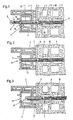
- the fastening element 1 is used for mounting profiles 2, frames, plates or the like on a fixed substructure 3.
- a hollow plastic profile 2 which is reinforced by a steel profile 4, on one made of concrete blocks fixed substructure 3 to be attached.
- the profile 2 is practically on the fixed substructure 3 or on the finishing plaster 5, but with the fastening element according to the invention the possibility here to maintain any necessary distance for a possible height or side compensation of a frame or a profile and still achieve a proper fastening by the fastening element 1.
- a bore 6 is made through the profile 2 and the steel profile and into the fixed substructure 3, into which the dowel 7 is then driven in with the screw 8 already inserted.
- the screw After insertion, the screw is screwed into the dowel 7, and this can be done until the screw head 9 is practically sunk on the corresponding surface of the profile 2 and thus closes the through hole.
- the corresponding length of the anchoring plug 10 can also be used to bridge cavities 11 in the fixed substructure 3 without problems.
- the fastening element 1 is further recessed in the profile 2 to be fastened, in which case the anchoring plug 10 also engages further in the fixed substructure.
- the dowel sleeve 12 it is also conceivable to make the dowel sleeve 12 a little longer, so that the screw head 9 can still be flush with the inlet opening 13.
- the screw 8 is provided with a thread extending over the entire length of the shaft 14, a first threaded section 15 being formed at the free end of the shaft 14 for screwing into the anchoring plug 10 and a second threaded section 16 adjacent to the screw head having a larger outside diameter than that first threaded section 15 is provided. Both thread sections 15 and 16 have the same thread pitch.
- the dowel 7 consists of a dowel sleeve 12 and an anchoring dowel 10, these two parts being fixed and integral with one another.
- the dowel sleeve 12 is in the mounting position of the fastening element 1 in the profile 2 to be fastened and is brought into operative connection with the screw section 16 of the screw near the screw head during the screwing-in process.
- the dowel 7 formed from the anchoring dowel 10 and the dowel sleeve 12 has an at least approximately constant outside diameter over its entire length.
- the free inside diameter of the dowel sleeve 12 corresponds approximately to the outside diameter of the threaded section 15 facing the free end of the shaft 14 of the screw 8, so that this threaded section 15 can be inserted into the area of the dowel sleeve 12 without turning.
- the dowel sleeve 12 has a longitudinal slot 17 which extends over at least approximately its entire length and which, in the embodiment shown, is designed to be open towards the free end of the dowel sleeve 12.
- a tearable or breakable web at the free end of the dowel sleeve 12 which is only broken open when the screw is screwed in.
- a plane 18 through the longitudinal slot 17 lies at a distance from the center axis 19 of the dowel.
- the anchoring dowel 10 and the dowel sleeve 12 have an outer profile in the form of sawtooth-like ribs 20 and 21, so that the proper anchoring is ensured in the fixed substructure and also in the profile to be fastened.
- These sawtooth-like ribs 20, 21 on the anchoring dowel 10 on the one hand and on the dowel sleeve 12 on the other are directed towards one another, as can be clearly seen in the drawings. It is therefore possible to optimally lock against the load and the direction of extension of the parts to be fastened together.
- a special design of the sawtooth-like ribs 21 in the region of the dowel sleeve 12 is particularly advantageous. Two or more rib sections 21 'and 21' offset in the axial direction are provided here, each of which leads over a partial area of the circumference of the dowel sleeve 12. As a result, the dowel sleeve 12 can be snapped into the webs of the profile 2 to be fastened at smaller axial distances.
- two diametrically opposed webs 23, 24 or corresponding knobs which protrude axially from one another by a thread pitch of the screw 8 and corresponding knobs are provided, which protrude into the dowel interior.
- Recesses 25, 26 are provided immediately adjacent to these webs 23, 24 or knobs in the direction of the anchoring plug 10, so that these webs 23, 24 can freely project. It is thereby possible when the screw is inserted into the dowel 7 that the webs 23 and 24 engage in the region of the free end of the screw shaft, so that a provisional locking between the screw and the dowel is achieved.
- This particular embodiment is shown in a central, sectioned area in FIG. 5 and in the enlarged view according to FIG. 11.
- the inner longitudinal recess 27 of the anchoring plug 10 has a plurality of longitudinal ribs 28 distributed around the circumference with grooves 29 remaining therebetween. These regions of the anchoring plug 10 are therefore not circumferentially located on the threaded section 15 to be screwed in the screw 8, but only at radially offset partial areas, so that the friction for screwing in is significantly reduced, but a sufficient hold is guaranteed against being pulled out.
- wing-like webs 30 are provided on the anchoring dowel 10 in an approximately radial direction, but at an acute angle to its longitudinal axis 19.
- Axial slots 31 are provided over the respective area of a wing-like web 30 and penetrate the wall of the anchoring plug 10.
- two pairs of wing-like webs 30, which follow one another in the axial direction, are provided on the end of the anchoring dowel 10 facing the dowel sleeve 12.
- one or two pairs of slot sections 32 are provided, which are arranged in the same angular orientation with respect to the center axis 19 of the plug as the wing-like webs. This provides an excellent expansion option for the anchoring plug 10 when the screw 8 is screwed in.
- the screw head 9 has at least approximately the same outside diameter as the dowel 7, so that a single hole has to be made in the fixed substructure and in the profile to be fastened, although the screw head 9 can nevertheless be countersunk in the profile to be fastened.
- the core diameter K of the second threaded section 16 corresponds approximately to the outside diameter D of the first threaded section 15 of the screw 8.
- the cross section of the screw blank in the area of the screw section 16 near the screw head is approximately 30% larger than its core diameter K.
- the thread flanks 33, 34 of both threaded sections 15, 16 have at their outermost edge 35, 36 a thickness R of at least 0.2 to 0.6 mm, preferably of 0.4 mm. Appropriate support or displacement of the dowel material is possible through the thread flanks without a cutting effect occurring.
- the outside diameter F of the screw section 16 near the screw head again corresponds approximately to the diameter 5 of the screw head 9.
- the first threaded section 15 of the screw 8 facing the free end of the shaft 14 is of double-start design, so that a considerably better hold of the screw in the anchoring plug 10 is ensured. This also has a positive effect on the manufacture of the screw, especially since the two threaded sections 15 and 16 have the same thread pitch.
- the screwing of the screw into the dowel is significantly improved if the free end of the shaft 14 has a penetration tip 37.
- the screw according to the invention therefore very easily penetrates into the anchoring dowel 10 and, due to this special design, can also be inserted into a substructure made of wood for direct use.
- the fastening element according to the invention consisting of dowels 7 and screw 8, represents a significant improvement in the fastening of profiles, frames, plates or the like to a fixed substructure. It is not only possible to fasten them properly in a rational manner, but by Appropriate loosening of the screw 8 is possible at any time to readjust or set up the frame to be fastened relative to the fixed substructure, with sufficient fastening also being provided if the profile to be fastened is not in direct contact with the substructure, but with a corresponding distance from it to be held.
Landscapes
- Engineering & Computer Science (AREA)
- General Engineering & Computer Science (AREA)
- Mechanical Engineering (AREA)
- Civil Engineering (AREA)
- Structural Engineering (AREA)
- Dowels (AREA)
- Joining Of Building Structures In Genera (AREA)
- Superconductors And Manufacturing Methods Therefor (AREA)
- Saccharide Compounds (AREA)
- Diaphragms For Electromechanical Transducers (AREA)
- Slide Fasteners, Snap Fasteners, And Hook Fasteners (AREA)
- Measurement Of Velocity Or Position Using Acoustic Or Ultrasonic Waves (AREA)
- Ultra Sonic Daignosis Equipment (AREA)
- Flanged Joints, Insulating Joints, And Other Joints (AREA)
- Finger-Pressure Massage (AREA)
Applications Claiming Priority (2)
| Application Number | Priority Date | Filing Date | Title |
|---|---|---|---|
| AT0128289A AT392130B (de) | 1989-05-29 | 1989-05-29 | Befestigungselement |
| AT1282/89 | 1989-05-29 |
Publications (3)
| Publication Number | Publication Date |
|---|---|
| EP0400535A2 true EP0400535A2 (fr) | 1990-12-05 |
| EP0400535A3 EP0400535A3 (fr) | 1992-04-08 |
| EP0400535B1 EP0400535B1 (fr) | 1994-07-06 |
Family
ID=3510516
Family Applications (1)
| Application Number | Title | Priority Date | Filing Date |
|---|---|---|---|
| EP90110077A Expired - Lifetime EP0400535B1 (fr) | 1989-05-29 | 1990-05-28 | Dispositif d'attache |
Country Status (5)
| Country | Link |
|---|---|
| EP (1) | EP0400535B1 (fr) |
| AT (2) | AT392130B (fr) |
| DE (1) | DE59006342D1 (fr) |
| FI (1) | FI902657A7 (fr) |
| NO (1) | NO902349L (fr) |
Cited By (12)
| Publication number | Priority date | Publication date | Assignee | Title |
|---|---|---|---|---|
| EP1018602A1 (fr) * | 1999-01-05 | 2000-07-12 | Julius Blum Gesellschaft m.b.H. | Ferrure pour meubles |
| EP0952294A3 (fr) * | 1998-04-22 | 2000-08-09 | Adolf Würth GmbH & Co. KG | Fixation pour cadres de fenêtres |
| DE102005046092A1 (de) * | 2005-09-27 | 2007-03-29 | Fischerwerke Artur Fischer Gmbh & Co. Kg | Spreizdübel für die Befestigung von Dämmstoffplatten |
| EP1798362A3 (fr) * | 2005-12-16 | 2008-06-04 | Sebastian Fuchs | Fixation d'un profilé de cadre d'un cadre de porte ou de fenêtre dans une ouverture dans un mur d'un bâtiment |
| WO2008030507A3 (fr) * | 2006-09-06 | 2008-12-04 | Illinois Tool Works | Dispositif de fixation pour cloison sèche |
| DE102007040368A1 (de) * | 2007-08-17 | 2009-02-19 | Adolf Würth GmbH & Co. KG | Spreizdübel |
| NL2001824C2 (nl) * | 2008-07-18 | 2010-01-19 | Alcoa Architectuursystemen | Montageschroef, montagebus, montagesamenstel en methode van monteren. |
| US7934895B2 (en) | 2003-10-10 | 2011-05-03 | Illinois Tool Works Inc. | Self-drilling anchor |
| US8192123B2 (en) | 2003-10-10 | 2012-06-05 | Illinois Tool Works Inc. | Drywall fastener |
| GB2490683A (en) * | 2011-05-10 | 2012-11-14 | Fss Fire & Security Solutions Ltd | Blast resistant window with strengthening insert |
| EP2541077A3 (fr) * | 2011-06-28 | 2013-10-02 | fischerwerke GmbH & Co. KG | Assemblage à cheville pour un montage d'espacement |
| EP3702629A1 (fr) * | 2019-02-28 | 2020-09-02 | Adolf Würth GmbH & Co. KG | Ensemble de montage universel permettant de monter un cadre sur un terrain naturel |
Families Citing this family (4)
| Publication number | Priority date | Publication date | Assignee | Title |
|---|---|---|---|---|
| AT398461B (de) * | 1992-08-14 | 1994-12-27 | Semperit Ag | Dübelhalter |
| US7661917B2 (en) | 2003-10-10 | 2010-02-16 | Illinois Tool Works, Inc. | Three piece garage hook |
| US8057147B2 (en) | 2008-07-03 | 2011-11-15 | Illinois Tool Works Inc | Self-drilling anchor |
| US7883307B2 (en) | 2009-02-27 | 2011-02-08 | Illinois Tool Works Inc. | Self-drilling fastener |
Family Cites Families (7)
| Publication number | Priority date | Publication date | Assignee | Title |
|---|---|---|---|---|
| DE7706596U1 (de) * | 1978-08-24 | Tox-Duebel-Werk Richard W. Heckhausen Kg, 7762 Bodman | Spreizdübel-Zubehörteil | |
| NL287956A (fr) * | 1962-02-06 | |||
| US3883258A (en) * | 1973-05-24 | 1975-05-13 | Kenneth E Hewson | Plastic dowel pin and wood joint assembly |
| US4283986A (en) * | 1979-09-26 | 1981-08-18 | Illinois Tool Works Inc. | Self-penetrating wallboard anchor |
| DE3310321A1 (de) * | 1983-03-22 | 1984-09-27 | Böhm, Otto, 8130 Starnberg | Schraubenkombination |
| DE3429585A1 (de) * | 1984-08-10 | 1986-02-20 | Alfons 5758 Fröndenberg Knoche | Aus einem kunststoffspreizduebel und einer befestigungsschraube bestehender befestigungssatz |
| DE3733854A1 (de) * | 1987-10-07 | 1989-04-27 | Fischer Artur Werke Gmbh | Verbundduebel |
-
1989
- 1989-05-29 AT AT0128289A patent/AT392130B/de not_active IP Right Cessation
-
1990
- 1990-05-28 EP EP90110077A patent/EP0400535B1/fr not_active Expired - Lifetime
- 1990-05-28 DE DE59006342T patent/DE59006342D1/de not_active Expired - Fee Related
- 1990-05-28 FI FI902657A patent/FI902657A7/fi not_active Application Discontinuation
- 1990-05-28 AT AT90110077T patent/ATE108247T1/de not_active IP Right Cessation
- 1990-05-28 NO NO90902349A patent/NO902349L/no unknown
Cited By (14)
| Publication number | Priority date | Publication date | Assignee | Title |
|---|---|---|---|---|
| EP0952294A3 (fr) * | 1998-04-22 | 2000-08-09 | Adolf Würth GmbH & Co. KG | Fixation pour cadres de fenêtres |
| US6287044B1 (en) | 1999-01-05 | 2001-09-11 | Julius Blum Gesellschaft M.B.H. | Fitting |
| EP1018602A1 (fr) * | 1999-01-05 | 2000-07-12 | Julius Blum Gesellschaft m.b.H. | Ferrure pour meubles |
| US7934895B2 (en) | 2003-10-10 | 2011-05-03 | Illinois Tool Works Inc. | Self-drilling anchor |
| US8192123B2 (en) | 2003-10-10 | 2012-06-05 | Illinois Tool Works Inc. | Drywall fastener |
| DE102005046092A1 (de) * | 2005-09-27 | 2007-03-29 | Fischerwerke Artur Fischer Gmbh & Co. Kg | Spreizdübel für die Befestigung von Dämmstoffplatten |
| EP1798362A3 (fr) * | 2005-12-16 | 2008-06-04 | Sebastian Fuchs | Fixation d'un profilé de cadre d'un cadre de porte ou de fenêtre dans une ouverture dans un mur d'un bâtiment |
| WO2008030507A3 (fr) * | 2006-09-06 | 2008-12-04 | Illinois Tool Works | Dispositif de fixation pour cloison sèche |
| DE102007040368A1 (de) * | 2007-08-17 | 2009-02-19 | Adolf Würth GmbH & Co. KG | Spreizdübel |
| EP2025952A3 (fr) * | 2007-08-17 | 2009-10-14 | Adolf Würth GmbH & Co. KG | Piton à expansion |
| NL2001824C2 (nl) * | 2008-07-18 | 2010-01-19 | Alcoa Architectuursystemen | Montageschroef, montagebus, montagesamenstel en methode van monteren. |
| GB2490683A (en) * | 2011-05-10 | 2012-11-14 | Fss Fire & Security Solutions Ltd | Blast resistant window with strengthening insert |
| EP2541077A3 (fr) * | 2011-06-28 | 2013-10-02 | fischerwerke GmbH & Co. KG | Assemblage à cheville pour un montage d'espacement |
| EP3702629A1 (fr) * | 2019-02-28 | 2020-09-02 | Adolf Würth GmbH & Co. KG | Ensemble de montage universel permettant de monter un cadre sur un terrain naturel |
Also Published As
| Publication number | Publication date |
|---|---|
| NO902349L (no) | 1990-11-30 |
| EP0400535A3 (fr) | 1992-04-08 |
| EP0400535B1 (fr) | 1994-07-06 |
| DE59006342D1 (de) | 1994-08-11 |
| NO902349D0 (no) | 1990-05-28 |
| ATE108247T1 (de) | 1994-07-15 |
| FI902657A7 (fi) | 1990-11-30 |
| AT392130B (de) | 1991-01-25 |
| ATA128289A (de) | 1990-07-15 |
| FI902657A0 (fi) | 1990-05-28 |
Similar Documents
| Publication | Publication Date | Title |
|---|---|---|
| EP0169335B1 (fr) | Cheville | |
| EP0400535B1 (fr) | Dispositif d'attache | |
| EP0344429B1 (fr) | Cheville expansible en matière plastique | |
| DD255765A5 (de) | Duebel aus kunststoff | |
| DE1500891B1 (de) | Befestigungseinsatz fuer Leichtbau-Schichtverbundplatten | |
| DE19642914C2 (de) | Dübel | |
| EP1235988B1 (fr) | Vis pour fixer avec un ecart, des panneaux de recouvrement ou des rails sur une infrastructure | |
| EP0019782A2 (fr) | Cheville métallique creuse | |
| EP0171745B1 (fr) | Dispositif de fixation consistant en une cheville d'écartement en matière plastique et une vis de fixation | |
| EP1582684B1 (fr) | Vis pour la fixation de profilés creux en matière plastique renforcés par des profilés métalliques sur une structure de support | |
| DE3148043A1 (de) | "duebel- und bolzenanordnung" | |
| DE2430217C2 (de) | Dübel aus Kunststoff mit verlängertem Schaft und Einschlagsperre | |
| DE3045474C2 (fr) | ||
| DE2229657B2 (de) | Montageplatte fuer moebelscharniere | |
| DE8401123U1 (de) | Formschlußdübel für Beton | |
| DE3018975A1 (de) | Befestigungssatz | |
| DE20121563U1 (de) | Schraube zum Befestigen einer Schalungsplatte | |
| DE3726594C2 (fr) | ||
| DE4324598A1 (de) | Dämmstoffhalter mit einem aufspreizbaren Dübelschaft | |
| DE20018425U1 (de) | Schraube zur Verankerung eines Hohlprofils an einem Unterbau | |
| DE2637797A1 (de) | Spreizduebel | |
| DE3401768C2 (de) | Mauerkanten-Schutzleistenanordnung | |
| EP0864049B1 (fr) | Cheville avec douille pourvue de saillies | |
| DE3021635A1 (de) | Spreizduebel mit einer beidseitig spreizbaren metallhuelse | |
| DE7825757U1 (de) | Aus Spreizdübel und Befestigungsschraube bestehender Befestigungssatz |
Legal Events
| Date | Code | Title | Description |
|---|---|---|---|
| PUAI | Public reference made under article 153(3) epc to a published international application that has entered the european phase |
Free format text: ORIGINAL CODE: 0009012 |
|
| AK | Designated contracting states |
Kind code of ref document: A2 Designated state(s): AT BE CH DE DK ES FR GB GR IT LI LU NL SE |
|
| PUAL | Search report despatched |
Free format text: ORIGINAL CODE: 0009013 |
|
| AK | Designated contracting states |
Kind code of ref document: A3 Designated state(s): AT BE CH DE DK ES FR GB GR IT LI LU NL SE |
|
| 17P | Request for examination filed |
Effective date: 19920421 |
|
| 17Q | First examination report despatched |
Effective date: 19930322 |
|
| RAP1 | Party data changed (applicant data changed or rights of an application transferred) |
Owner name: SFS INDUSTRIE HOLDING AG |
|
| GRAA | (expected) grant |
Free format text: ORIGINAL CODE: 0009210 |
|
| AK | Designated contracting states |
Kind code of ref document: B1 Designated state(s): AT BE CH DE DK ES FR GB GR IT LI LU NL SE |
|
| PG25 | Lapsed in a contracting state [announced via postgrant information from national office to epo] |
Ref country code: IT Free format text: LAPSE BECAUSE OF FAILURE TO SUBMIT A TRANSLATION OF THE DESCRIPTION OR TO PAY THE FEE WITHIN THE PRE;WARNING: LAPSES OF ITALIAN PATENTS WITH EFFECTIVE DATE BEFORE 2007 MAY HAVE OCCURRED AT ANY TIME BEFORE 2007. THE CORRECT EFFECTIVE DATE MAY BE DIFFERENT FROM THE ONE RECORDED.SCRIBED TIME-LIMIT Effective date: 19940706 Ref country code: FR Effective date: 19940706 Ref country code: GB Effective date: 19940706 Ref country code: GR Free format text: LAPSE BECAUSE OF FAILURE TO SUBMIT A TRANSLATION OF THE DESCRIPTION OR TO PAY THE FEE WITHIN THE PRESCRIBED TIME-LIMIT Effective date: 19940706 Ref country code: BE Effective date: 19940706 Ref country code: NL Effective date: 19940706 Ref country code: DK Effective date: 19940706 Ref country code: ES Free format text: THE PATENT HAS BEEN ANNULLED BY A DECISION OF A NATIONAL AUTHORITY Effective date: 19940706 |
|
| REF | Corresponds to: |
Ref document number: 108247 Country of ref document: AT Date of ref document: 19940715 Kind code of ref document: T |
|
| REF | Corresponds to: |
Ref document number: 59006342 Country of ref document: DE Date of ref document: 19940811 |
|
| PG25 | Lapsed in a contracting state [announced via postgrant information from national office to epo] |
Ref country code: SE Effective date: 19941006 |
|
| EN | Fr: translation not filed | ||
| NLV1 | Nl: lapsed or annulled due to failure to fulfill the requirements of art. 29p and 29m of the patents act | ||
| GBV | Gb: ep patent (uk) treated as always having been void in accordance with gb section 77(7)/1977 [no translation filed] |
Effective date: 19940706 |
|
| PLBE | No opposition filed within time limit |
Free format text: ORIGINAL CODE: 0009261 |
|
| STAA | Information on the status of an ep patent application or granted ep patent |
Free format text: STATUS: NO OPPOSITION FILED WITHIN TIME LIMIT |
|
| PG25 | Lapsed in a contracting state [announced via postgrant information from national office to epo] |
Ref country code: LU Free format text: LAPSE BECAUSE OF NON-PAYMENT OF DUE FEES Effective date: 19950531 |
|
| 26N | No opposition filed | ||
| PGFP | Annual fee paid to national office [announced via postgrant information from national office to epo] |
Ref country code: CH Payment date: 19980407 Year of fee payment: 9 |
|
| PGFP | Annual fee paid to national office [announced via postgrant information from national office to epo] |
Ref country code: AT Payment date: 19980415 Year of fee payment: 9 |
|
| PGFP | Annual fee paid to national office [announced via postgrant information from national office to epo] |
Ref country code: DE Payment date: 19980421 Year of fee payment: 9 |
|
| PG25 | Lapsed in a contracting state [announced via postgrant information from national office to epo] |
Ref country code: AT Free format text: LAPSE BECAUSE OF NON-PAYMENT OF DUE FEES Effective date: 19990528 |
|
| PG25 | Lapsed in a contracting state [announced via postgrant information from national office to epo] |
Ref country code: CH Free format text: LAPSE BECAUSE OF NON-PAYMENT OF DUE FEES Effective date: 19990531 Ref country code: LI Free format text: LAPSE BECAUSE OF NON-PAYMENT OF DUE FEES Effective date: 19990531 |
|
| REG | Reference to a national code |
Ref country code: CH Ref legal event code: PL |
|
| PG25 | Lapsed in a contracting state [announced via postgrant information from national office to epo] |
Ref country code: DE Free format text: LAPSE BECAUSE OF NON-PAYMENT OF DUE FEES Effective date: 20000301 |