EP0400537A2 - Relais polarisé d'armature de contact - Google Patents
Relais polarisé d'armature de contact Download PDFInfo
- Publication number
- EP0400537A2 EP0400537A2 EP90110084A EP90110084A EP0400537A2 EP 0400537 A2 EP0400537 A2 EP 0400537A2 EP 90110084 A EP90110084 A EP 90110084A EP 90110084 A EP90110084 A EP 90110084A EP 0400537 A2 EP0400537 A2 EP 0400537A2
- Authority
- EP
- European Patent Office
- Prior art keywords
- coil
- tongue
- permanent magnet
- contact
- pole
- Prior art date
- Legal status (The legal status is an assumption and is not a legal conclusion. Google has not performed a legal analysis and makes no representation as to the accuracy of the status listed.)
- Withdrawn
Links
Images

Classifications
-
- H—ELECTRICITY
- H01—ELECTRIC ELEMENTS
- H01H—ELECTRIC SWITCHES; RELAYS; SELECTORS; EMERGENCY PROTECTIVE DEVICES
- H01H51/00—Electromagnetic relays
- H01H51/22—Polarised relays
- H01H51/2236—Polarised relays comprising pivotable armature, pivoting at extremity or bending point of armature
- H01H51/2245—Armature inside coil
- H01H51/2254—Contact forms part of armature
-
- H—ELECTRICITY
- H01—ELECTRIC ELEMENTS
- H01H—ELECTRIC SWITCHES; RELAYS; SELECTORS; EMERGENCY PROTECTIVE DEVICES
- H01H1/00—Contacts
- H01H1/64—Protective enclosures, baffle plates, or screens for contacts
- H01H1/645—Protective enclosures, baffle plates, or screens for contacts containing getter material
Definitions
- the invention relates to a polarized armature contact relay with a coil body, which carries a winding between two end flanges, and with two tongue anchors, which are arranged opposite and parallel to one another within the hollow coil body.
- DE-OS 29 31 409 specifies various possibilities for arranging two changeover contacts with tongue anchors within a common coil former. Examples are also shown in which two tongue anchors are arranged opposite one another in parallel in a single axial cavity of the coil body in such a way that in each coil flange a contacting end of a tongue anchor can be switched between two contacting pole pieces. However, there the fastening end of an armature in the respective coil flange is covered and shielded by an upstream pole shoe in the axial direction, so that the magnetic flux circuits, in particular the permanent flux circuits, are inadequately closed. As can be seen from the description, the arrangement there is therefore essentially only suitable for monostable relays.
- the object of the present invention is to provide an improved relay of the type mentioned at the outset, which enables good guidance of the magnetic flux for all circuits and in particular also a good adjustment of the respective permanent magnetic circuits in order to enable an optimal switching behavior for both changeover contacts.
- the exposed ends of the two tongue anchors and the separately provided flux plates for the two changeover contacts each create separate, well-closed permanent magnet circuits.
- the four-pole permanent magnets resting on the end faces of the pole shoes are easily accessible for magnetic adjustment, so that the response values for each changeover contact and within the changeover contacts can also be set separately and optimally for both sides.
- the pole shoes which each lie in pairs vertically next to one another on the end faces of the coil body flanges and form their connecting elements downward, are essentially designed as flat parts, the narrow sides facing the tongue anchor forming contact sections coated with contact material.
- These contact sections can expediently be slightly bent or angled into the coil body interior, but the contacting surfaces are cut parallel to the respective side surface of the tongue anchor. This results in a somewhat larger contact area; in addition, the contact area is shifted somewhat into the inside of the coil body, so that the end of the tongue armature does not abut the flat permanent magnet or an insulating film inserted between the permanent magnet and pole pieces.
- At least one getter body is expediently arranged in the interior of the coil body in the region between the two tongue anchors.
- each tongue anchor has a separate contact space which extends through the coil body parallel to the coil axis.
- the intermediate wall separating the two contact spaces gives the coil former better dimensional stability.
- a separate getter body is expediently arranged in a corresponding recess for each contact space.
- the relay shown in FIGS. 1 to 4 has a coil former 1 with an excitation winding 11, which is applied between two coil former flanges 2 and 3. With a bistable characteristic of the relay, two excitation windings could of course also be provided.
- the coil former has two parallel contact spaces 12 and 13 which are continuous in the axially parallel direction and are separated from one another by a partition 14 which is completely or partially continuous in the longitudinal direction.
- This intermediate wall 14 increases the dimensional stability of the bobbin; it could also be interrupted if necessary to create a connection between the two contact spaces 12 and 13.
- a cavity 15 or 16 is formed from each flange side, which is connected to the adjacent contact space 12 or 13 and serves to receive a getter body 17.
- the bobbin 1 is with all parts and Recesses designed axially symmetrical to a central axis running perpendicular to the installation plane and to the coil axis, so that two contact units symmetrical to this central axis can be formed from each of the two flanges 2 and 3.
- the individual parts are completely identical for both contact units, which keeps the number of different parts small and simplifies the overall production.
- An armature contact element 4 is inserted in each of the two contact spaces - in the opposite direction.
- This armature contact element each has a contact tongue 41 and on its fastening end in the area of the clamping on both sides a freely cut fastening tab 42 which is connected to the contact tongue 41 via a torsion bar 43.
- the fastening tabs 42 are each inserted into bearing grooves 21, 31 of the bobbin flange 2 and 3 and glued there.
- the contact tongue 41 can be adjusted in the center or to one side, as described for example in DE-A-33 38 198.
- Each armature contact element has an angled connecting part 44 relative to the tongue 41, which rests on the end face of the respective coil flange and is used for magnetic coupling.
- a connector pin 45 for the electrical connection is formed at the bottom.
- pole pieces 5 and 6 are each formed essentially as flat sheets which are arranged in a vertical plane with respect to the connection plane of the relay and also perpendicular to the coil axis. The pole pieces are between projecting ribs 22 and 32 and lugs 23 and 33 of the respective coils body flange 2 or 3 clamped.
- these ribs 22 and 32 or lugs 23 and 33 is such that they correspond approximately to the thickness of the pole pieces 5 and 6.
- the pole pieces have integrally formed connecting pins 51 and 61 63 is formed (see FIG. 4).
- these contact surfaces are very slightly convex in order to ensure uniformly good contact even when the tongue anchor is slightly inclined.
- the contact spaces 12 and 13 in the coil former can be provisionally closed off by insulating foils 71 and 72, which are attached and optionally welded on the end.
- insulating foils 71 and 72 which are attached and optionally welded on the end.
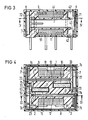
- a permanent magnet 7 is placed on the outer surface of the pole shoe pairs, with the interposition of the insulating film 72 already mentioned.
- two flux plates 8 are each pushed laterally over the coil body, in such a way that one flux plate 8 couples the outer poles of a permanent magnet 7 to the connecting part 44 of the associated armature contact element 4.
- the aforementioned insulating film 71 is inserted between the connecting part 44 and the flux plate 8 in order to ensure electrical insulation in addition to the sealing function.
- the relay arrangement thus obtained is placed in a cap 9, so that only the connection pins 45, 51 and 61 of the armature contact elements or the pole shoes and the coil connection pins 24 and 34 anchored in the coil flanges 2 and 3 protrude.
- the relay is then potted in the cap 9, which can itself be made of plastic, as a result of which all parts are fixed to one another.
- the films 71 and 72 prevent the potting compound 91 from entering the interior of the contact spaces 12 and 13 flows.
- the permanent magnets 7 with their two permanent magnet regions can be magnetized and adjusted in the desired manner, as will be explained below with reference to FIG. 4.
- the cap 9 can also be omitted if the relay is cast or molded in a mold.
- each pole shoe is assigned its own permanent magnet area, that is to say the permanent magnet area 7 a and the pole shoe 6 the permanent magnet area 7 b.
- This magnetization of the respective permanent magnet 7 can be carried out by magnetization poles applied from the outside.
- a comparison of each individual area 7a or 7b is then carried out, whereby asymmetries in the construction and in the materials of the magnetic circuit can be compensated for by a different comparison of these areas.
- a comparison is also possible in such a way that a certain tongue anchor always responds first, so that a certain switching sequence is set from the outset.
- the adjustment can be carried out on the fully assembled and encapsulated relay, so that the permanent magnet regions 7a and 7b mentioned can be generated in the correct assignment to the pole pieces and regardless of the physical arrangement of the rectangular permanent magnet 7.
Landscapes
- Physics & Mathematics (AREA)
- Electromagnetism (AREA)
- Electromagnets (AREA)
- Separation By Low-Temperature Treatments (AREA)
Applications Claiming Priority (2)
| Application Number | Priority Date | Filing Date | Title |
|---|---|---|---|
| DE8906678U DE8906678U1 (de) | 1989-05-31 | 1989-05-31 | Polarisiertes Ankerkontaktrelais |
| DE8906678U | 1989-05-31 |
Publications (2)
| Publication Number | Publication Date |
|---|---|
| EP0400537A2 true EP0400537A2 (fr) | 1990-12-05 |
| EP0400537A3 EP0400537A3 (fr) | 1992-05-13 |
Family
ID=6839691
Family Applications (1)
| Application Number | Title | Priority Date | Filing Date |
|---|---|---|---|
| EP19900110084 Withdrawn EP0400537A3 (fr) | 1989-05-31 | 1990-05-28 | Relais polarisé d'armature de contact |
Country Status (4)
| Country | Link |
|---|---|
| US (1) | US5008641A (fr) |
| EP (1) | EP0400537A3 (fr) |
| JP (1) | JPH0371538U (fr) |
| DE (1) | DE8906678U1 (fr) |
Families Citing this family (2)
| Publication number | Priority date | Publication date | Assignee | Title |
|---|---|---|---|---|
| DE102007025338B4 (de) * | 2007-05-31 | 2015-02-05 | Tyco Electronics Amp Gmbh | Verfahren zum Abdichten eines Gehäuses und elektrische Komponente |
| CN202650990U (zh) * | 2012-07-02 | 2013-01-02 | 宁波福特继电器有限公司 | 一种小型大功率磁保持继电器 |
Family Cites Families (10)
| Publication number | Priority date | Publication date | Assignee | Title |
|---|---|---|---|---|
| FR2314576A1 (fr) * | 1975-06-11 | 1977-01-07 | Matsushita Electric Works Ltd | Relais a lame |
| DE2717451C2 (de) * | 1977-04-20 | 1980-08-14 | Sds-Elektro Gmbh, 8024 Deisenhofen | Elektromagnetisches Relais |
| DE2954352C2 (de) * | 1979-03-30 | 1984-12-13 | Hans 8024 Deisenhofen Sauer | Gepoltes Zungenkontaktrelais |
| DE3240184C1 (de) * | 1982-10-29 | 1984-03-22 | Siemens AG, 1000 Berlin und 8000 München | Elektromagnetisches Relais |
| DE3240215C1 (de) * | 1982-10-29 | 1984-03-22 | Siemens AG, 1000 Berlin und 8000 München | Elektromagnetisches Relais |
| DE3338198A1 (de) * | 1983-10-20 | 1985-05-02 | Siemens AG, 1000 Berlin und 8000 München | Elektromagnetisches relais und verfahren zu dessen herstellung |
| DE3338208A1 (de) * | 1983-10-20 | 1985-05-02 | Siemens AG, 1000 Berlin und 8000 München | Elektromagnetisches relais und verfahren zu dessen herstellung |
| US4672344A (en) * | 1985-04-19 | 1987-06-09 | Siemens Aktiengesellschaft | Polarized electromagnetic relay |
| JPS6379304A (ja) * | 1986-06-02 | 1988-04-09 | Fuji Electric Co Ltd | 有極電磁石装置 |
| DE58905723D1 (de) * | 1988-03-25 | 1993-11-04 | Siemens Ag | Polarisiertes elektromagnetisches mehrkontaktrelais. |
-
1989
- 1989-05-31 DE DE8906678U patent/DE8906678U1/de not_active Expired - Lifetime
-
1990
- 1990-05-28 EP EP19900110084 patent/EP0400537A3/fr not_active Withdrawn
- 1990-05-31 JP JP1990056613U patent/JPH0371538U/ja active Pending
- 1990-05-31 US US07/531,839 patent/US5008641A/en not_active Expired - Fee Related
Also Published As
| Publication number | Publication date |
|---|---|
| EP0400537A3 (fr) | 1992-05-13 |
| US5008641A (en) | 1991-04-16 |
| JPH0371538U (fr) | 1991-07-19 |
| DE8906678U1 (de) | 1990-09-27 |
Similar Documents
| Publication | Publication Date | Title |
|---|---|---|
| DE3202704C2 (de) | Hubmagnet-Betätigungseinrichtung | |
| DE2934558C2 (de) | Elektromagnetisches Relais | |
| DE2454967A1 (de) | Elektromagnetisches relais | |
| DE69501597T2 (de) | Elektromagnetische Einrichtung | |
| DE3303665A1 (de) | Polarisiertes elektromagnetisches relais | |
| DE3586200T2 (de) | Elektromagnetisches relais. | |
| EP0017129B1 (fr) | Relais polarisé à lames de contact | |
| EP0876674B1 (fr) | Relais electromagnetique de structure etroite et procede permettant de le produire | |
| DE3347602A1 (de) | Polarisiertes elektromagnetisches relais | |
| DE3508327A1 (de) | Stromwandler mit einem rechteckigen eisenkern | |
| DE3047608C2 (de) | Elektromagnetisches Relais | |
| EP0140285B1 (fr) | Relais électromagnétique et méthode pour sa fabrication | |
| EP0334336B1 (fr) | Relais électromagnétique polarisé à contacts multiples | |
| EP0400537A2 (fr) | Relais polarisé d'armature de contact | |
| EP0074577B1 (fr) | Relais électromagnétique polarisé | |
| DE2233005B2 (de) | Spulenkoerper-baueinheit | |
| DE2711480C2 (de) | Elektromagnetisches Miniaturrelais | |
| DE3437544A1 (de) | Elektromagnetisches relais | |
| EP0198492B1 (fr) | Relais électromagnétique polarisé | |
| DE3025814A1 (de) | Elektromagnetisches relais | |
| DE69105694T2 (de) | Verfahren zur Herstellung einer Elektromagnetanordnung für Elektroventilen. | |
| DE1537798C3 (de) | Koordinatenschalter | |
| EP0410984B1 (fr) | Corps de bobine et son procede de fabrication | |
| DE3224070C2 (de) | Polarisiertes Relais | |
| EP0252343B1 (fr) | Procédé d'ajustage pour un relais électromagnétique ainsi que relais ajusté selon ce procédé |
Legal Events
| Date | Code | Title | Description |
|---|---|---|---|
| PUAI | Public reference made under article 153(3) epc to a published international application that has entered the european phase |
Free format text: ORIGINAL CODE: 0009012 |
|
| AK | Designated contracting states |
Kind code of ref document: A2 Designated state(s): AT CH DE ES FR GB IT LI |
|
| 17P | Request for examination filed |
Effective date: 19901205 |
|
| PUAL | Search report despatched |
Free format text: ORIGINAL CODE: 0009013 |
|
| AK | Designated contracting states |
Kind code of ref document: A3 Designated state(s): AT CH DE ES FR GB IT LI |
|
| STAA | Information on the status of an ep patent application or granted ep patent |
Free format text: STATUS: THE APPLICATION IS DEEMED TO BE WITHDRAWN |
|
| 18D | Application deemed to be withdrawn |
Effective date: 19931201 |