EP0400540A2 - Dispositif pour lire un document - Google Patents
Dispositif pour lire un document Download PDFInfo
- Publication number
- EP0400540A2 EP0400540A2 EP90110087A EP90110087A EP0400540A2 EP 0400540 A2 EP0400540 A2 EP 0400540A2 EP 90110087 A EP90110087 A EP 90110087A EP 90110087 A EP90110087 A EP 90110087A EP 0400540 A2 EP0400540 A2 EP 0400540A2
- Authority
- EP
- European Patent Office
- Prior art keywords
- reading
- reading device
- document
- document reading
- carriage
- Prior art date
- Legal status (The legal status is an assumption and is not a legal conclusion. Google has not performed a legal analysis and makes no representation as to the accuracy of the status listed.)
- Withdrawn
Links
Images

Classifications
-
- H—ELECTRICITY
- H04—ELECTRIC COMMUNICATION TECHNIQUE
- H04N—PICTORIAL COMMUNICATION, e.g. TELEVISION
- H04N1/00—Scanning, transmission or reproduction of documents or the like, e.g. facsimile transmission; Details thereof
- H04N1/04—Scanning arrangements, i.e. arrangements for the displacement of active reading or reproducing elements relative to the original or reproducing medium, or vice versa
- H04N1/12—Scanning arrangements, i.e. arrangements for the displacement of active reading or reproducing elements relative to the original or reproducing medium, or vice versa using the sheet-feed movement or the medium-advance or the drum-rotation movement as the slow scanning component, e.g. arrangements for the main-scanning
- H04N1/126—Arrangements for the main scanning
- H04N1/128—Arrangements for the main scanning using a scanning head arranged for linear reciprocating motion
-
- G—PHYSICS
- G06—COMPUTING OR CALCULATING; COUNTING
- G06K—GRAPHICAL DATA READING; PRESENTATION OF DATA; RECORD CARRIERS; HANDLING RECORD CARRIERS
- G06K13/00—Conveying record carriers from one station to another, e.g. from stack to punching mechanism
- G06K13/02—Conveying record carriers from one station to another, e.g. from stack to punching mechanism the record carrier having longitudinal dimension comparable with transverse dimension, e.g. punched card
- G06K13/06—Guiding cards; Checking correct operation of card-conveying mechanisms
- G06K13/067—Checking presence, absence, correct position, or moving status of cards
-
- G—PHYSICS
- G06—COMPUTING OR CALCULATING; COUNTING
- G06K—GRAPHICAL DATA READING; PRESENTATION OF DATA; RECORD CARRIERS; HANDLING RECORD CARRIERS
- G06K13/00—Conveying record carriers from one station to another, e.g. from stack to punching mechanism
- G06K13/02—Conveying record carriers from one station to another, e.g. from stack to punching mechanism the record carrier having longitudinal dimension comparable with transverse dimension, e.g. punched card
- G06K13/08—Feeding or discharging cards
-
- G—PHYSICS
- G06—COMPUTING OR CALCULATING; COUNTING
- G06K—GRAPHICAL DATA READING; PRESENTATION OF DATA; RECORD CARRIERS; HANDLING RECORD CARRIERS
- G06K7/00—Methods or arrangements for sensing record carriers, e.g. for reading patterns
- G06K7/08—Methods or arrangements for sensing record carriers, e.g. for reading patterns by means detecting the change of an electrostatic or magnetic field, e.g. by detecting change of capacitance between electrodes
- G06K7/082—Methods or arrangements for sensing record carriers, e.g. for reading patterns by means detecting the change of an electrostatic or magnetic field, e.g. by detecting change of capacitance between electrodes using inductive or magnetic sensors
- G06K7/083—Methods or arrangements for sensing record carriers, e.g. for reading patterns by means detecting the change of an electrostatic or magnetic field, e.g. by detecting change of capacitance between electrodes using inductive or magnetic sensors inductive
- G06K7/084—Methods or arrangements for sensing record carriers, e.g. for reading patterns by means detecting the change of an electrostatic or magnetic field, e.g. by detecting change of capacitance between electrodes using inductive or magnetic sensors inductive sensing magnetic material by relative movement detecting flux changes without altering its magnetised state
-
- H—ELECTRICITY
- H04—ELECTRIC COMMUNICATION TECHNIQUE
- H04N—PICTORIAL COMMUNICATION, e.g. TELEVISION
- H04N1/00—Scanning, transmission or reproduction of documents or the like, e.g. facsimile transmission; Details thereof
- H04N1/04—Scanning arrangements, i.e. arrangements for the displacement of active reading or reproducing elements relative to the original or reproducing medium, or vice versa
- H04N1/19—Scanning arrangements, i.e. arrangements for the displacement of active reading or reproducing elements relative to the original or reproducing medium, or vice versa using multi-element arrays
- H04N1/191—Scanning arrangements, i.e. arrangements for the displacement of active reading or reproducing elements relative to the original or reproducing medium, or vice versa using multi-element arrays the array comprising a one-dimensional [1D] array
- H04N1/1911—Simultaneously or substantially simultaneously scanning picture elements on more than one main scanning line, e.g. scanning in swaths
Definitions
- the invention relates to a document reading device according to the features of the preamble of claim 1.
- the present invention has for its object to provide a document reading device of the type mentioned in such a way that a read head adjustable to at least two lines is clearly guided in the respective setting and the switch from line to line can be carried out quickly and easily.
- FIG. 1 shows an optical reading head 1 which is attached to a reading carriage 2.
- This reading carriage 2 can be moved back and forth perpendicular to the drawing plane by means of a toothed belt drive 3, the reading head 1 being guided parallel to an insertion slot 4 for a reading object.
- the drive of the reading carriage is controlled in each of the two end positions by light barriers 5.
- This steel pin 7 is guided for the exact guidance of the reading head 1 along the reading line in an approximately U-shaped guide rail 8.
- a slide 9 On the side of the angle 6 facing away from the guide rail 8, a slide 9 is provided, on which the angle 6 is supported.
- a steel plate 11 with a very smooth surface is attached to the angle 6.
- a pressed-on ball bearing 12 is provided on the steel pin 7, which rolls with its lateral surface on an extended inner shoulder of the guide rail 8.
- a holding magnet 13 is integrated, which is arranged so recessed that a small gap of approximately 0.1 mm width is formed between the steel sheet 11 lying on the slider 9 and the holding magnet 13.
- the reading carriage 2 is kept vibration-free on the one hand, on the other hand, the holding force of the magnet 13 and the friction between steel sheet 11 and the plastic be standing slider 9 dimensioned so that the reading carriage 2 can still be moved quietly and frictionally against the force of the holding magnet 13.
- the reading head 1 is set to the upper line of a document or ID card that is guided in the insertion slot 4. Since the reading carriage 1 carrying the reading head 1 is pivotably mounted on a horizontal pivot axis 14 in the vertical direction, it is possible to set the reading head 1 to at least one further line on the ID card.
- the reading carriage 2 shows the arrangement in a position of the reading head 1 which is offset by one reading line from FIG. 1.
- the reading carriage 2 In a lateral end position, the reading carriage 2 is pivoted so far downward about the pivot axis 14 that the steel pin 7 moves into a position below the guide rail 8 extending further guide rail 15 dips.
- the two guide rails 8, 15 can expediently be designed as a one-piece double rail.
- the downward swiveling movement of the reading carriage 2 results in a slight relative movement of the angle 6 or the steel sheet 11 with respect to the sliding piece 9 and at the same time a relative movement between the sliding piece 9 and the rod 10 guided in the elongated hole and consequently acting as a floating bearing.
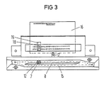
- FIG 3 shows the reading device in a schematic representation in the region of the insertion slot 4 with a card-shaped ID card inserted from above, for example a machine-readable ID card.
- the correct position of the ID card 16 is determined by a switch provided in the insertion slot, for example by a light barrier 17.
- the reading head aligned with the upper reading line is symbolically indicated by the smaller rectangular reading window 18 and by the somewhat larger lighting window 19.
- the reading head is on the left Edge of the device, specifically above the starting position marked with S, at which the steel pin 7 connected to the reading carriage 2 via the angle 6 (see FIG. 1) is located.
- the reading carriage 2 now moves from this starting position S to the right, the steel pin 7 or the ball bearing 12 pressed onto the steel pin 7 being guided in the guide rail 8.
- a switch-like reversing element is provided, which is designed such that the steel pin 7 is pushed into the plane of the second guide rail 15 running underneath.
- the direction of the reading carriage drive, controlled by the light barrier 5, is reversed, so that the reading carriage 2 is now moved back from right to left.
- the steel pin 7 slides into the lower guide rail 15 with the result that the reading head is set to the lower reading line.
- the steel pin 7 On the left edge of the guide rail 15, the steel pin 7 is pushed back into the plane of the upper guide rail 8 and finally reaches the original starting position S.
- the device can also be designed for more than two-line reading operation.
- the exact guidance of the steel pin 7 in the guide rails 8, 15 guarantees, due to the fact that the steel pin 7 is firmly connected to the reading carriage 2, an equally exact guidance of the reading head along the lines, so that the reading position which is as optimal as possible for good reading quality is preserved even with mechanical shocks.
- the use of one guardrail per reading line and the special shape of the rail end areas not only enable exact line routing, but also simple line switching while avoiding mechanically switchable points.
Landscapes
- Engineering & Computer Science (AREA)
- Physics & Mathematics (AREA)
- General Physics & Mathematics (AREA)
- Theoretical Computer Science (AREA)
- Multimedia (AREA)
- Signal Processing (AREA)
- Artificial Intelligence (AREA)
- Computer Vision & Pattern Recognition (AREA)
- Facsimile Scanning Arrangements (AREA)
Applications Claiming Priority (2)
| Application Number | Priority Date | Filing Date | Title |
|---|---|---|---|
| DE8906681U | 1989-05-31 | ||
| DE8906681U DE8906681U1 (de) | 1989-05-31 | 1989-05-31 | Beleglesevorrichtung |
Publications (2)
| Publication Number | Publication Date |
|---|---|
| EP0400540A2 true EP0400540A2 (fr) | 1990-12-05 |
| EP0400540A3 EP0400540A3 (fr) | 1991-10-23 |
Family
ID=6839695
Family Applications (1)
| Application Number | Title | Priority Date | Filing Date |
|---|---|---|---|
| EP19900110087 Withdrawn EP0400540A3 (fr) | 1989-05-31 | 1990-05-28 | Dispositif pour lire un document |
Country Status (2)
| Country | Link |
|---|---|
| EP (1) | EP0400540A3 (fr) |
| DE (1) | DE8906681U1 (fr) |
Family Cites Families (5)
| Publication number | Priority date | Publication date | Assignee | Title |
|---|---|---|---|---|
| US3646570A (en) * | 1970-02-13 | 1972-02-29 | Scope Inc | Printing head mechanism |
| IT939793B (it) * | 1971-09-06 | 1973-02-10 | Olivetti & Co Spa | Dispositivo di scrittura per macchine calcolatrici elettroniche |
| DE2445081C3 (de) * | 1974-09-20 | 1985-12-05 | Siemens AG, 1000 Berlin und 8000 München | Anordnung zur Steuerung der Bewegung eines Druckerwagens für Druckwerke, insbesondere für Fernschreib- und Schreibmaschinen |
| GB1534898A (en) * | 1976-09-30 | 1978-12-06 | Trend Communications Ltd | Printers |
| DE3522059A1 (de) * | 1985-06-20 | 1987-01-02 | Eilhard Dipl Ing Schacht | Strichcode- (barcode-) leseschablone |
-
1989
- 1989-05-31 DE DE8906681U patent/DE8906681U1/de not_active Expired
-
1990
- 1990-05-28 EP EP19900110087 patent/EP0400540A3/fr not_active Withdrawn
Also Published As
| Publication number | Publication date |
|---|---|
| DE8906681U1 (de) | 1989-07-27 |
| EP0400540A3 (fr) | 1991-10-23 |
Similar Documents
| Publication | Publication Date | Title |
|---|---|---|
| DE3107199A1 (de) | Vorrichtung zum schneiden und/oder stanzen | |
| DE2052498A1 (de) | Mikrofilm Betrachtungsgerät | |
| DE2430407A1 (de) | Mosaik-drahtdruckkopf | |
| EP0281501A1 (fr) | Appareil de balayage optique | |
| DE4421122C3 (de) | Bildabtastgerät | |
| EP0416354B1 (fr) | Microtome à coulisseau | |
| EP0400540A2 (fr) | Dispositif pour lire un document | |
| DE3927817A1 (de) | Vorrichtung zur oeffnungsbegrenzung fuer eine schwenktuer | |
| DE4441152C1 (de) | Schiebetor zum Verschließen einer Einfahrt | |
| DE3030413C1 (de) | Anlage zum Belegen von Spanplatten,Faserplatten u.dgl. mit Verguetungsfolienzuschnitten | |
| DE69103659T2 (de) | Tragbarer Drucker. | |
| DE3341813C2 (fr) | ||
| DE3807076C2 (fr) | ||
| DE2457741C2 (de) | Aufbau und Lagerung eines Registrierelementes einer elektrographischen Registriervorrichtung | |
| EP0054978B1 (fr) | Dispositif de sciage | |
| DE3921519C2 (fr) | ||
| DE1799007C3 (de) | Vorrichtung zum Justieren des Magnetkopfes bei einem Mehrspur-Magnetbandgerät | |
| EP0369162A2 (fr) | Imprimante comportant un poste d'impression basculant | |
| DE3145001A1 (de) | Vorrichtung zur beschickung mindestens eines positionierkopfes einer automatischen maschine zur montage von bauelementen | |
| EP0595010B1 (fr) | Dispositif pour retenir une carte à puce | |
| DE2934273A1 (de) | Vorrichtung zum bewegen der werkzeuge von automatischen zeichenmaschinen. | |
| EP0315818A2 (fr) | Machine pour impression sérigraphique | |
| DE3919879A1 (de) | Beschriftungsvorrichtung | |
| DE2302501C3 (de) | Einstellbare Lagerung für ein Steuerfunktionen auslösendes Steuerlineal | |
| DE2438185C3 (de) | Laufwagenzeichenmaschine |
Legal Events
| Date | Code | Title | Description |
|---|---|---|---|
| PUAI | Public reference made under article 153(3) epc to a published international application that has entered the european phase |
Free format text: ORIGINAL CODE: 0009012 |
|
| AK | Designated contracting states |
Kind code of ref document: A2 Designated state(s): AT BE CH DE DK ES FR GB IT LI NL SE |
|
| 17P | Request for examination filed |
Effective date: 19901205 |
|
| PUAL | Search report despatched |
Free format text: ORIGINAL CODE: 0009013 |
|
| PUAF | Information related to the publication of a search report (a3 document) modified or deleted |
Free format text: ORIGINAL CODE: 0009199SEPU |
|
| PUAL | Search report despatched |
Free format text: ORIGINAL CODE: 0009013 |
|
| AK | Designated contracting states |
Kind code of ref document: A3 Designated state(s): AT BE CH DE DK ES FR GB IT LI NL SE |
|
| D17D | Deferred search report published (deleted) | ||
| AK | Designated contracting states |
Kind code of ref document: A3 Designated state(s): AT BE CH DE DK ES FR GB IT LI NL SE |
|
| 17Q | First examination report despatched |
Effective date: 19940428 |
|
| STAA | Information on the status of an ep patent application or granted ep patent |
Free format text: STATUS: THE APPLICATION IS DEEMED TO BE WITHDRAWN |
|
| 18D | Application deemed to be withdrawn |
Effective date: 19940909 |