EP0400593B2 - Protection pour composants d'installations de commutation à isolement gazeux contre les claquage à cause d'arcs de défaut internes - Google Patents
Protection pour composants d'installations de commutation à isolement gazeux contre les claquage à cause d'arcs de défaut internes Download PDFInfo
- Publication number
- EP0400593B2 EP0400593B2 EP90110227A EP90110227A EP0400593B2 EP 0400593 B2 EP0400593 B2 EP 0400593B2 EP 90110227 A EP90110227 A EP 90110227A EP 90110227 A EP90110227 A EP 90110227A EP 0400593 B2 EP0400593 B2 EP 0400593B2
- Authority
- EP
- European Patent Office
- Prior art keywords
- arc
- conductor
- inner conductor
- protector
- bushing
- Prior art date
- Legal status (The legal status is an assumption and is not a legal conclusion. Google has not performed a legal analysis and makes no representation as to the accuracy of the status listed.)
- Expired - Lifetime
Links
- 239000004020 conductor Substances 0.000 claims description 83
- 239000000463 material Substances 0.000 claims description 9
- 230000003993 interaction Effects 0.000 claims description 8
- RYGMFSIKBFXOCR-UHFFFAOYSA-N Copper Chemical compound [Cu] RYGMFSIKBFXOCR-UHFFFAOYSA-N 0.000 claims description 4
- 229910052802 copper Inorganic materials 0.000 claims description 4
- 239000010949 copper Substances 0.000 claims description 4
- 230000015572 biosynthetic process Effects 0.000 claims description 3
- 230000001012 protector Effects 0.000 claims 8
- 230000007547 defect Effects 0.000 claims 1
- 239000011810 insulating material Substances 0.000 description 4
- 239000002184 metal Substances 0.000 description 3
- 229910052751 metal Inorganic materials 0.000 description 3
- 230000005012 migration Effects 0.000 description 3
- 238000013508 migration Methods 0.000 description 3
- 238000007664 blowing Methods 0.000 description 1
- 230000015556 catabolic process Effects 0.000 description 1
- 238000011161 development Methods 0.000 description 1
- 230000018109 developmental process Effects 0.000 description 1
- 238000005538 encapsulation Methods 0.000 description 1
- 238000010438 heat treatment Methods 0.000 description 1
- 238000009413 insulation Methods 0.000 description 1
- 230000006855 networking Effects 0.000 description 1
- 239000012811 non-conductive material Substances 0.000 description 1
- 239000011347 resin Substances 0.000 description 1
- 229920005989 resin Polymers 0.000 description 1
- 230000006641 stabilisation Effects 0.000 description 1
- 238000011105 stabilization Methods 0.000 description 1
Images

Classifications
-
- H—ELECTRICITY
- H02—GENERATION; CONVERSION OR DISTRIBUTION OF ELECTRIC POWER
- H02B—BOARDS, SUBSTATIONS OR SWITCHING ARRANGEMENTS FOR THE SUPPLY OR DISTRIBUTION OF ELECTRIC POWER
- H02B13/00—Arrangement of switchgear in which switches are enclosed in, or structurally associated with, a casing, e.g. cubicle
- H02B13/02—Arrangement of switchgear in which switches are enclosed in, or structurally associated with, a casing, e.g. cubicle with metal casing
- H02B13/035—Gas-insulated switchgear
- H02B13/065—Means for detecting or reacting to mechanical or electrical defects
Definitions
- the invention relates to protection for components of gas-insulated switchgear in the event of internal arcing faults against burnout, the components essentially consisting of an at least on the inside conductive sleeve as the outer conductor and a tubular inner conductor held by supporters and wherein to generate a rotation of the arc on the inner conductor in Distance from each other elongated conductor tracks are provided, which are inclined towards the central axis of the inner conductor at an angle which is dimensioned such that when an arc occurs due to the conductor tracks serving as the current lead a magnetic field which is soft in interaction with the magnetic field of the Uchtbogen an azimuthal Generates force that is stronger than the azimuthal forces that can arise from possible accidental inclinations of the arc.
- CH-A-596 686 Protection for components of gas-insulated switchgear of the type mentioned at the outset is known from CH-A-596 686.
- the insert is electrically connected to the inner conductor at one end and electrically insulated from the inner conductor at its other end. Conductor tracks are formed through the incisions in the insert.
- the conductor tracks take up the base point of a moving arc, and current then flows through them, which generates a magnetic field which interacts with the magnetic field generated by the arc. As a result, the arc is forced to rotate and there is no selective heat load on the metal encapsulation of the high-voltage system.
- a disadvantage is the comparatively great design effort for attaching the conductor tracks to the inner conductor, because the conductor tracks are located on a separate component which has to be mounted on the inner conductor.
- the invention has for its object to provide protection for components of gas-insulated switchgear in the event of internal arcing faults against burnout, which can be manufactured inexpensively with little design effort.
- the conductor tracks are designed as webs of the inner conductor which are separated from one another by slots.
- the solutions according to the invention have the advantage that components of gas-insulated switchgear can be protected against burn-out due to internal arcing faults using simple structural measures - and thus economically producible. There is no need for additional inserts such as coils or sheet metal jackets, nor for additional material.
- the arc By placing the arc on a rotational path, it rotates in front of the supporter without damaging it or blowing the wall in front of the supporter. This rotation of the arc is possible without damaging the affected component for a relatively long period of time for such damage.
- the system can be switched off without any problems during this period.
- the invention is based on the idea that stabilization of the arc base on the system casing must be prevented.
- Such a rotation of the arc is brought about in that the current supply to the arc is designed in such a way that its magnetic field interacts with the magnetic field of the arc current, which results in an azimuthal force on the arc, which is thereby set into rotation.
- Figure 1 shows a section of a component of a gas-insulated switchgear, which is cut on the left transverse to its axis and on the right in the direction of the longitudinal axis.
- An inner conductor 1 is surrounded by an outer conductor 2, which also serves as a sheath.
- the SF 6 is located as an insulating gas between the inner conductor 1 and the outer conductor 2.
- the cylinder coordinate system ez, er and e ⁇ which is entered in FIG. 1, serves to explain the invention shown below.
- An arc 6 travels in such a component in the direction of the arrow when the current is fed to the inner conductor from the left side. The return flow of the current in the outer conductor then takes place in the opposite direction.
- the arc runs in the axial direction until it strikes a support.
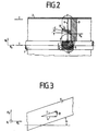
- Figure 2 shows an embodiment according to the first alternative solution in section.
- the inner conductor 1 is surrounded by the outer conductor 2 and held by a support 3 so that the axis of the inner conductor coincides with the axis of the outer conductor.
- the inner conductor 1 is designed as a tube
- the support 3 consists of an insulating material, for example cast resin
- the outer conductor 2 can be designed as a metallic sheath or as a sheath made of non-conductive material with a conductive layer on the inside.
- the inner conductor 1 in its area 4 adjoining the support 3 consists of a plurality of parallel conductor tracks 5, which are evenly distributed over the circumference. These conductor tracks 5 are interrupted by insulating strips and have a predetermined angle ⁇ to the axial direction.
- FIG. 3 shows a section of a conductor track 5 which has an angle ⁇ to the axial direction and in which the division of the current I into its components in Z and in the ⁇ direction is shown.
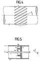
- These conductor tracks 5 are arranged, for example, on the inner conductor 1 in the region 4, as is shown in FIG. 4.
- the angle ⁇ of the conductor track 5 must be dimensioned such that when an arc 6 occurs, through the conductor tracks 5 serving as the power supply to the arc 6, a magnetic field is generated which, in interaction with the magnetic field of the arc 6, generates an azimuthal force that is stronger than the azimuthal forces that can arise from possible, randomly occurring inclinations of the arc 6. In this way, rotation of the arc can be guaranteed with absolute certainty.
- the conductor tracks 5 can be designed as webs on a tubular inner conductor 1, wherein these webs can be produced, for example, by incorporating slots.
- the conductor strips 5 can, however, also be arranged on the inner conductor 1 in the form of ribs made of particularly conductive material. For the formation of the corresponding magnetic field, it may be sufficient if these ribs made of particularly conductive material have gaps at the bottom of which there is less conductive material.
- the areas 4, 4 ′ of the inner conductor 1 and / or the outer conductor 2 adjoining the support 3 can be made of a material that has good running properties for the arc in order to optimize the blow-through protection. such as copper. This favors the rotation of the arc, the base point moves even faster, which means that the heating on the outer conductor 2 is reduced. In this way, the effectiveness of the arrangement can be increased further.
- Figure 5 shows protection for components of gas-insulated switchgear according to the second alternative solution.
- the component is cut along the axis in the area of a support.
- the inner conductor 1, the outer conductor 2 and the support 3 can be seen in section.
- the supporter 3 holds the inner conductor 1 so that its axis coincides with the axis of the outer conductor 2 in this embodiment.
- the support 3 is equipped on its side facing the power source with a circular elevation 7 projecting into the space between the inner conductor 1 and the outer conductor 2.
- the elevation 7 can be designed as a cylindrical ring, as a toroidal elevation or in another shape.
- the elevation 7 consists of insulating material, either the same insulating material as the material of the support 3 or from a particularly edge-resistant insulating material.
- the support 3 can also be equipped on both sides with such an elevation 7. This is particularly expedient in those parts of the system which can be supplied with current from one side or the other by networking or capacities in the event of a short circuit.
- the height of such an annular elevation 7 of the support 3, in comparison to the outer and inner regions of the support 3 adjoining the conductors 1, 2, must be dimensioned such that the interaction of the magnetic field, caused by the current flow of the conductors 1, 2 , with the magnetic field which arises from the arc 6 'curved by the elevation 7, generates such a strong force that it presses the arc 6' out of the position forced by means of the elevation 7 and the formation of a standing, stable arc is no longer possible is.
- This second alternative solution with an elevation 7 of the support 3 can of course be combined with the conductor tracks 5 of the first alternative solution. This is possible in such a way that conductor tracks 5 are arranged on the inner conductor 1. With this combination, the protection for components of gas-insulated switchgear can be made particularly effective, since the forces causing the rotation are considerably increased and the speed of rotation of the arc is correspondingly high, thus reducing the stress caused by the arc base on the sheath.
Landscapes
- Engineering & Computer Science (AREA)
- Power Engineering (AREA)
- Arc-Extinguishing Devices That Are Switches (AREA)
Claims (8)
- Protection contre la brûlure pour des composants d'installations de distribution isolées au gaz, dans le cas d'erreurs internes d'arc, ces composants étant constitués sensiblement par une douille conductrice au moins sur la face intérieure et servant de conducteur extérieur (2) et par un conducteur intérieur (1) tubulaire maintenu par un isolateur support (3) et, pour générer une rotation de l'arc (6) à la périphérie du conducteur intérieur (1), une pluralité de pistes conductives (5) allongées qui s'étendent parallèlement entre elles étant disposées à distance les unes des autres dans une zone attenante à l'isolateur support (3), pistes qui sont inclinées par rapport à l'axe médian du conducteur intérieur (1) avec un angle (α) qui est mesuré de sorte qu'à l'apparition de l'arc (6) il se produit, à travers les pistes conductives servant d'amenée de courant à l'arc (6), un champ magnétique qui, en interaction avec le champ magnétique de l'arc (6), génère une force azimutale qui est plus forte que les forces azimutales pouvant résulter d'éventuelles positions inclinées de l'arc (6) se produisant par hasard, caractérisée en ce que
les pistes conductives (5) sont réalisées comme des moulures du conducteur intérieur (1), séparées les unes des autres par des fentes. - Protection pour des composants d'installations de distribution isolées au gaz selon la revendication 1,
caractérisée en ce que
des zones (4) du conducteur intérieur (1), attenantes à l'isolateur support (3), se composent d'une matière présentant une bonne conductibilité électrique. - Protection pour des composants d'installations de distribution isolées au gaz selon la revendication 2,
caractérisée en ce que
la matière est du cuivre. - Protection pour des composants d'installations de distribution isolées au gaz selon d'un des revendications 1 à 3,
caractérisée en ce que
l'isolateur support (3) présente, au moins sur l'une de ses faces tournées vers la source de courant, une élévation (7) circulaire, s'engageant dans l'espace entre le conducteur intérieur (1) et le conducteur extérieur (2). - Protection pour des composants selon la revendication 4,
caractérisée en ce que
l'isolateur support (3) présente, des deux côtés, des élévations (7) circulaires, s'engageant dans l'espace entre le conducteur intérieur (1) et le conducteur extérieur (2). - Protection pour des composants selon la revendication 4 ou 5, caractérisée en ce que
la hauteur de l'élévation circulaire (7) de l'isolateur support (3) en comparaison avec les zones extérieures et intérieures de l'isolateur support (3), attenantes aux conducteurs (1, 2), est dimensionnée de sorte que l'interaction du champ magnétique causé par le flux de courant des conducteurs (1, 2) avec le champ magnétique, qui résulte de l'arc courbé (6') par l'élévation (7), génère une force si importante que celle-ci expulse l'arc (6') de sa position imposée au moyen de l'élévation (7) et que la formation d'un arc stable, droit n'est plus possible. - Protection pour des composants selon l'un ou plusieurs des revendications 4 à 6,
caractérisée en ce que
les zones (4, 4') du conducteur intérieur (1) et du conducteur extérieur (2), attenantes à l'isolateur support (3) se composent d'une matière présentant de bonnes propriétés de propagation pour l'arc (6'). - Protection pour des composants selon la revendication 7,
caractérisée en ce que
la matière est du cuivre.
Applications Claiming Priority (2)
| Application Number | Priority Date | Filing Date | Title |
|---|---|---|---|
| DE3917988A DE3917988A1 (de) | 1989-06-02 | 1989-06-02 | Schutz fuer komponenten gasisolierter schaltanlagen bei internen lichtbogenfehlern gegen druchbrennen |
| DE3917988 | 1989-06-02 |
Publications (3)
| Publication Number | Publication Date |
|---|---|
| EP0400593A1 EP0400593A1 (fr) | 1990-12-05 |
| EP0400593B1 EP0400593B1 (fr) | 1994-03-02 |
| EP0400593B2 true EP0400593B2 (fr) | 1997-08-13 |
Family
ID=6381907
Family Applications (1)
| Application Number | Title | Priority Date | Filing Date |
|---|---|---|---|
| EP90110227A Expired - Lifetime EP0400593B2 (fr) | 1989-06-02 | 1990-05-30 | Protection pour composants d'installations de commutation à isolement gazeux contre les claquage à cause d'arcs de défaut internes |
Country Status (2)
| Country | Link |
|---|---|
| EP (1) | EP0400593B2 (fr) |
| DE (2) | DE3917988A1 (fr) |
Families Citing this family (1)
| Publication number | Priority date | Publication date | Assignee | Title |
|---|---|---|---|---|
| FR2739984B1 (fr) * | 1995-10-13 | 1997-11-14 | Gec Alsthom T & D Sa | Barre conductrice pour appareil electrique haute tension a enveloppe metallique |
Family Cites Families (7)
| Publication number | Priority date | Publication date | Assignee | Title |
|---|---|---|---|---|
| FR1352906A (fr) * | 1962-12-29 | 1964-02-21 | Merlin Gerin | Isolateur pour conducteurs à gaine coaxiale |
| DE2360071C2 (de) * | 1973-11-29 | 1984-12-13 | Siemens AG, 1000 Berlin und 8000 München | Gekapselte mit Schwefelhexafluorid (SF↓6↓) isolierte Hochspannungseinrichtung |
| CH596686A5 (fr) * | 1976-09-23 | 1978-03-15 | Sprecher & Schuh Ag | |
| DE2710843A1 (de) * | 1977-03-12 | 1978-09-14 | Licentia Gmbh | Gekapselte, druckgasisolierte hochspannungsanlage |
| DE3112009A1 (de) * | 1981-03-26 | 1982-10-07 | Siemens AG, 1000 Berlin und 8000 München | "kontaktanordnung fuer vakuumschalter" |
| DE3302595A1 (de) * | 1983-01-27 | 1984-08-02 | Calor-Emag Elektrizitäts-Aktiengesellschaft, 4030 Ratingen | Kontaktanordnung fuer vakuumschalter |
| DE8333056U1 (de) * | 1983-11-17 | 1986-07-31 | Ritter Starkstromtechnik GmbH & Co, 4600 Dortmund | Störlichtbogenfeste Hochspannungs-Schaltzelle |
-
1989
- 1989-06-02 DE DE3917988A patent/DE3917988A1/de not_active Ceased
-
1990
- 1990-05-30 DE DE90110227T patent/DE59004727D1/de not_active Expired - Fee Related
- 1990-05-30 EP EP90110227A patent/EP0400593B2/fr not_active Expired - Lifetime
Also Published As
| Publication number | Publication date |
|---|---|
| DE59004727D1 (de) | 1994-04-07 |
| DE3917988A1 (de) | 1990-12-13 |
| EP0400593B1 (fr) | 1994-03-02 |
| EP0400593A1 (fr) | 1990-12-05 |
Similar Documents
| Publication | Publication Date | Title |
|---|---|---|
| DE2526037C3 (de) | Überspannungsableiter | |
| DE10205905B4 (de) | Vollbereichs-Hochspannungs-Strombegrenzungssicherung | |
| DE2443141B2 (de) | Vakuumschalter mit einem Vakuumgehäuse | |
| DE2339564A1 (de) | Leiterschutz mit ableiter und ausfall-ueberwachungsschaltung | |
| DE19933495A1 (de) | Unterbrecher für Schaltautomaten | |
| DE3220357A1 (de) | Hochspannungs- und allzweckhochspannungsschmelzsicherung | |
| CH665306A5 (de) | Strombegrenzende sicherung. | |
| DE2946800C2 (de) | Vakuumschalter | |
| DE3900684A1 (de) | Schaltkontakt fuer vakuumschalter | |
| CH635461A5 (de) | Starkstromschalter mit sprengausloesung. | |
| DE3319010C2 (fr) | ||
| DE2427708A1 (de) | Strombegrenzende schmelzsicherung | |
| DE3105133A1 (de) | Gasisolierter trennschalter | |
| EP0400593B2 (fr) | Protection pour composants d'installations de commutation à isolement gazeux contre les claquage à cause d'arcs de défaut internes | |
| DE3823747C2 (fr) | ||
| DE2600306A1 (de) | Vakuumschalter mit zahlreichen parallel geschalteten kontaktstueckpaaren | |
| DE3334682C2 (fr) | ||
| DE1933438A1 (de) | Hochvakuumschaltgeraet | |
| EP0106296B1 (fr) | Coupe-circuit haute tension à fort pouvoir de coupure | |
| DE2007667A1 (de) | Hochspannungsleitung | |
| DE2624595C3 (de) | Kontaktanordnung für Druckgasschalter | |
| EP0739071B1 (fr) | Ligne haute tension à isolation gazeuse | |
| DE2903426C2 (de) | Elektromagnetische Lichtbogenlöscheinrichtung | |
| DE3943447A1 (de) | Schutz fuer komponenten gasisolierter schaltanlagen bei internen lichtbogenfehlern gegen durchbrennen | |
| DE1438244A1 (de) | UEberspannungsableiter |
Legal Events
| Date | Code | Title | Description |
|---|---|---|---|
| PUAI | Public reference made under article 153(3) epc to a published international application that has entered the european phase |
Free format text: ORIGINAL CODE: 0009012 |
|
| AK | Designated contracting states |
Kind code of ref document: A1 Designated state(s): CH DE FR LI NL SE |
|
| 17P | Request for examination filed |
Effective date: 19901206 |
|
| 17Q | First examination report despatched |
Effective date: 19930222 |
|
| GRAA | (expected) grant |
Free format text: ORIGINAL CODE: 0009210 |
|
| AK | Designated contracting states |
Kind code of ref document: B1 Designated state(s): CH DE FR LI NL SE |
|
| REF | Corresponds to: |
Ref document number: 59004727 Country of ref document: DE Date of ref document: 19940407 |
|
| ET | Fr: translation filed | ||
| PLBI | Opposition filed |
Free format text: ORIGINAL CODE: 0009260 |
|
| 26 | Opposition filed |
Opponent name: SIEMENS AG Effective date: 19941130 |
|
| EAL | Se: european patent in force in sweden |
Ref document number: 90110227.7 |
|
| NLR1 | Nl: opposition has been filed with the epo |
Opponent name: SIEMENS AG |
|
| REG | Reference to a national code |
Ref country code: CH Ref legal event code: PUE Owner name: LICENTIA PATENT- VERWALTUNGS-GMBH TRANSFER- AEG EN |
|
| NLS | Nl: assignments of ep-patents |
Owner name: AEG ENERGIETECHNIK GMBH |
|
| PLAW | Interlocutory decision in opposition |
Free format text: ORIGINAL CODE: EPIDOS IDOP |
|
| RAP2 | Party data changed (patent owner data changed or rights of a patent transferred) |
Owner name: AEG ENERGIETECHNIK GMBH |
|
| REG | Reference to a national code |
Ref country code: FR Ref legal event code: TP |
|
| NLT2 | Nl: modifications (of names), taken from the european patent patent bulletin |
Owner name: AEG ENERGIETECHNIK GMBH |
|
| PLAW | Interlocutory decision in opposition |
Free format text: ORIGINAL CODE: EPIDOS IDOP |
|
| PGFP | Annual fee paid to national office [announced via postgrant information from national office to epo] |
Ref country code: FR Payment date: 19970516 Year of fee payment: 8 |
|
| PGFP | Annual fee paid to national office [announced via postgrant information from national office to epo] |
Ref country code: SE Payment date: 19970522 Year of fee payment: 8 |
|
| PGFP | Annual fee paid to national office [announced via postgrant information from national office to epo] |
Ref country code: CH Payment date: 19970523 Year of fee payment: 8 |
|
| PGFP | Annual fee paid to national office [announced via postgrant information from national office to epo] |
Ref country code: NL Payment date: 19970529 Year of fee payment: 8 |
|
| PUAH | Patent maintained in amended form |
Free format text: ORIGINAL CODE: 0009272 |
|
| STAA | Information on the status of an ep patent application or granted ep patent |
Free format text: STATUS: PATENT MAINTAINED AS AMENDED |
|
| PGFP | Annual fee paid to national office [announced via postgrant information from national office to epo] |
Ref country code: DE Payment date: 19970717 Year of fee payment: 8 |
|
| 27A | Patent maintained in amended form |
Effective date: 19970813 |
|
| AK | Designated contracting states |
Kind code of ref document: B2 Designated state(s): CH DE FR LI NL SE |
|
| REG | Reference to a national code |
Ref country code: CH Ref legal event code: AEN Free format text: AUFRECHTERHALTUNG DES PATENTES IN GEAENDERTER FORM |
|
| NLR2 | Nl: decision of opposition | ||
| NLR3 | Nl: receipt of modified translations in the netherlands language after an opposition procedure | ||
| ET3 | Fr: translation filed ** decision concerning opposition | ||
| PG25 | Lapsed in a contracting state [announced via postgrant information from national office to epo] |
Ref country code: SE Free format text: LAPSE BECAUSE OF NON-PAYMENT OF DUE FEES Effective date: 19980531 Ref country code: LI Free format text: LAPSE BECAUSE OF NON-PAYMENT OF DUE FEES Effective date: 19980531 Ref country code: FR Free format text: LAPSE BECAUSE OF NON-PAYMENT OF DUE FEES Effective date: 19980531 Ref country code: CH Free format text: LAPSE BECAUSE OF NON-PAYMENT OF DUE FEES Effective date: 19980531 |
|
| PG25 | Lapsed in a contracting state [announced via postgrant information from national office to epo] |
Ref country code: NL Free format text: LAPSE BECAUSE OF NON-PAYMENT OF DUE FEES Effective date: 19981201 |
|
| REG | Reference to a national code |
Ref country code: CH Ref legal event code: PL |
|
| EUG | Se: european patent has lapsed |
Ref document number: 90110227.7 |
|
| NLV4 | Nl: lapsed or anulled due to non-payment of the annual fee |
Effective date: 19981201 |
|
| PG25 | Lapsed in a contracting state [announced via postgrant information from national office to epo] |
Ref country code: DE Free format text: LAPSE BECAUSE OF NON-PAYMENT OF DUE FEES Effective date: 19990302 |
|
| REG | Reference to a national code |
Ref country code: FR Ref legal event code: ST |