EP0400596A2 - Cutting device for a folder in a printing machine - Google Patents
Cutting device for a folder in a printing machine Download PDFInfo
- Publication number
- EP0400596A2 EP0400596A2 EP90110234A EP90110234A EP0400596A2 EP 0400596 A2 EP0400596 A2 EP 0400596A2 EP 90110234 A EP90110234 A EP 90110234A EP 90110234 A EP90110234 A EP 90110234A EP 0400596 A2 EP0400596 A2 EP 0400596A2
- Authority
- EP
- European Patent Office
- Prior art keywords
- cutting
- web
- cutting device
- air
- grooves
- Prior art date
- Legal status (The legal status is an assumption and is not a legal conclusion. Google has not performed a legal analysis and makes no representation as to the accuracy of the status listed.)
- Granted
Links
Images


Classifications
-
- B—PERFORMING OPERATIONS; TRANSPORTING
- B26—HAND CUTTING TOOLS; CUTTING; SEVERING
- B26D—CUTTING; DETAILS COMMON TO MACHINES FOR PERFORATING, PUNCHING, CUTTING-OUT, STAMPING-OUT OR SEVERING
- B26D7/00—Details of apparatus for cutting, cutting-out, stamping-out, punching, perforating, or severing by means other than cutting
- B26D7/08—Means for treating work or cutting member to facilitate cutting
-
- B—PERFORMING OPERATIONS; TRANSPORTING
- B41—PRINTING; LINING MACHINES; TYPEWRITERS; STAMPS
- B41F—PRINTING MACHINES OR PRESSES
- B41F13/00—Common details of rotary presses or machines
- B41F13/54—Auxiliary folding, cutting, collecting or depositing of sheets or webs
-
- B—PERFORMING OPERATIONS; TRANSPORTING
- B65—CONVEYING; PACKING; STORING; HANDLING THIN OR FILAMENTARY MATERIAL
- B65H—HANDLING THIN OR FILAMENTARY MATERIAL, e.g. SHEETS, WEBS, CABLES
- B65H23/00—Registering, tensioning, smoothing or guiding webs
- B65H23/04—Registering, tensioning, smoothing or guiding webs longitudinally
- B65H23/24—Registering, tensioning, smoothing or guiding webs longitudinally by fluid action, e.g. to retard the running web
-
- B—PERFORMING OPERATIONS; TRANSPORTING
- B65—CONVEYING; PACKING; STORING; HANDLING THIN OR FILAMENTARY MATERIAL
- B65H—HANDLING THIN OR FILAMENTARY MATERIAL, e.g. SHEETS, WEBS, CABLES
- B65H27/00—Special constructions, e.g. surface features, of feed or guide rollers for webs
-
- B—PERFORMING OPERATIONS; TRANSPORTING
- B65—CONVEYING; PACKING; STORING; HANDLING THIN OR FILAMENTARY MATERIAL
- B65H—HANDLING THIN OR FILAMENTARY MATERIAL, e.g. SHEETS, WEBS, CABLES
- B65H45/00—Folding thin material
- B65H45/12—Folding articles or webs with application of pressure to define or form crease lines
- B65H45/28—Folding in combination with cutting
-
- B—PERFORMING OPERATIONS; TRANSPORTING
- B26—HAND CUTTING TOOLS; CUTTING; SEVERING
- B26D—CUTTING; DETAILS COMMON TO MACHINES FOR PERFORATING, PUNCHING, CUTTING-OUT, STAMPING-OUT OR SEVERING
- B26D7/00—Details of apparatus for cutting, cutting-out, stamping-out, punching, perforating, or severing by means other than cutting
- B26D7/08—Means for treating work or cutting member to facilitate cutting
- B26D2007/082—Guiding or pushing a web into a favorable position by deflector means
-
- B—PERFORMING OPERATIONS; TRANSPORTING
- B65—CONVEYING; PACKING; STORING; HANDLING THIN OR FILAMENTARY MATERIAL
- B65H—HANDLING THIN OR FILAMENTARY MATERIAL, e.g. SHEETS, WEBS, CABLES
- B65H2404/00—Parts for transporting or guiding the handled material
- B65H2404/10—Rollers
- B65H2404/13—Details of longitudinal profile
- B65H2404/131—Details of longitudinal profile shape
- B65H2404/1316—Details of longitudinal profile shape stepped or grooved
- B65H2404/13161—Regularly spaced grooves
-
- B—PERFORMING OPERATIONS; TRANSPORTING
- B65—CONVEYING; PACKING; STORING; HANDLING THIN OR FILAMENTARY MATERIAL
- B65H—HANDLING THIN OR FILAMENTARY MATERIAL, e.g. SHEETS, WEBS, CABLES
- B65H2404/00—Parts for transporting or guiding the handled material
- B65H2404/10—Rollers
- B65H2404/13—Details of longitudinal profile
- B65H2404/131—Details of longitudinal profile shape
- B65H2404/1316—Details of longitudinal profile shape stepped or grooved
- B65H2404/13162—Helicoidal grooves
-
- B—PERFORMING OPERATIONS; TRANSPORTING
- B65—CONVEYING; PACKING; STORING; HANDLING THIN OR FILAMENTARY MATERIAL
- B65H—HANDLING THIN OR FILAMENTARY MATERIAL, e.g. SHEETS, WEBS, CABLES
- B65H2404/00—Parts for transporting or guiding the handled material
- B65H2404/10—Rollers
- B65H2404/13—Details of longitudinal profile
- B65H2404/133—Limited number of active elements on common axis
-
- B—PERFORMING OPERATIONS; TRANSPORTING
- B65—CONVEYING; PACKING; STORING; HANDLING THIN OR FILAMENTARY MATERIAL
- B65H—HANDLING THIN OR FILAMENTARY MATERIAL, e.g. SHEETS, WEBS, CABLES
- B65H2404/00—Parts for transporting or guiding the handled material
- B65H2404/10—Rollers
- B65H2404/14—Roller pairs
-
- Y—GENERAL TAGGING OF NEW TECHNOLOGICAL DEVELOPMENTS; GENERAL TAGGING OF CROSS-SECTIONAL TECHNOLOGIES SPANNING OVER SEVERAL SECTIONS OF THE IPC; TECHNICAL SUBJECTS COVERED BY FORMER USPC CROSS-REFERENCE ART COLLECTIONS [XRACs] AND DIGESTS
- Y10—TECHNICAL SUBJECTS COVERED BY FORMER USPC
- Y10T—TECHNICAL SUBJECTS COVERED BY FORMER US CLASSIFICATION
- Y10T83/00—Cutting
- Y10T83/202—With product handling means
- Y10T83/2066—By fluid current
- Y10T83/207—By suction means
-
- Y—GENERAL TAGGING OF NEW TECHNOLOGICAL DEVELOPMENTS; GENERAL TAGGING OF CROSS-SECTIONAL TECHNOLOGIES SPANNING OVER SEVERAL SECTIONS OF THE IPC; TECHNICAL SUBJECTS COVERED BY FORMER USPC CROSS-REFERENCE ART COLLECTIONS [XRACs] AND DIGESTS
- Y10—TECHNICAL SUBJECTS COVERED BY FORMER USPC
- Y10T—TECHNICAL SUBJECTS COVERED BY FORMER US CLASSIFICATION
- Y10T83/00—Cutting
- Y10T83/647—With means to convey work relative to tool station
- Y10T83/6472—By fluid current
Definitions
- blowing air nozzles On both sides of the incoming web 5, a plurality of blowing air nozzles, generally designated 10 or 11, are arranged.
- the side-by-side blowing air nozzles 10 are supplied with compressed air by means of an air supply line 12 and the side-by-side blowing air nozzles 11 are supplied with compressed air.
- Each blowing air nozzle expediently has e.g. 10 a clamp 14 which can be fixed in different angular positions on the air supply line 12 by means of a screw 15 which is only indicated schematically.
Landscapes
- Engineering & Computer Science (AREA)
- Mechanical Engineering (AREA)
- Life Sciences & Earth Sciences (AREA)
- Forests & Forestry (AREA)
- Folding Of Thin Sheet-Like Materials, Special Discharging Devices, And Others (AREA)
Abstract
Eine Schneidvorrichtung für ein Falzwerk einer Druckmaschine mit zwei Schneidzylindern für die senkrecht zugeführte Bahn und nachgeschalteten Transportbandleitungen, die über Umlenkrollen laufen und die abgeschnittenen Produkte zwischen sich weiterführen, umfaßt zur Schaffung einer Führung für einen exakten Einlauf der Produkte zwischen die Transportbandleitungen beiderseits der ankommenden Bahn in den Spalt zwischen Bahn und Schneidzylinder gerichtete Blasdüsen sowie Schneidzylinder mit Nuten zum Durchtritt der Blasluft parallel zur Bahn. 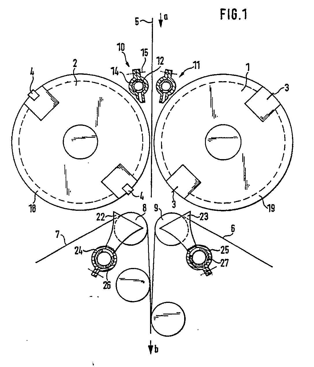
Description
Die Erfindung betrifft eine Schneidvorrichtung für ein Falzwerk einer Druckmaschine mit zwei Schneidzylindern für die senkrecht zugeführte Bahn und nachgeschalteten Transportbandleitungen, die über Umlenkrollen laufen und die abgeschnittenen Produkte zwischen sich weiterführen.The invention relates to a cutting device for a folding unit of a printing press with two cutting cylinders for the vertically fed web and downstream conveyor belt lines, which run over deflection rollers and carry the cut products between them.
Ein derartiges Falzwerk ist aus dem Prospekt "Lithoman M" in der Firma MAN Roland Druckmaschinen AG, Seite 6 bekannt. Bei diesem Falzwerk sind die geschnittenen Produkte auf dem Weg zwischen den Schneidzylindern einerseits und den Transportbändern andererseits ohne Führung. Hierbei ist nachteilig, daß die vorderen Schnittkanten der Produkte dazu neigen, für eine kurze Zeit an den Zähnen des Messers des einen Schneidzylinders haften zu bleiben. Löst sich die Vorderkante etwas verzögert von dem Schneidzylinder, so wird die Richtung in der das abgeschnittene Produkt von den Schneidzylindern abläuft, geändert. Die Vorderkante stößt dann gegen eine Umlenkrolle und bildet beim Einziehen zwischen die Transportbänder abgeknickte Ecken. Ein Haften der Vorderkanten an einen Schneidzylinder kann auch infolge einer elektrostatischen Aufladung auftreten. Derartige Aufladungen können nicht nur ungewollt während des Betriebes auftreten, sie werden vielmehr bei mehrlagigen Bahnen bewußt vorgesehen, um die einzelnen geschnittenen Bogen zusammenzuhalten.Such a folder is known from the brochure "Lithoman M" in the company MAN Roland Druckmaschinen AG,
Der Erfindung liegt die Aufgabe zugrunde eine Führung für die geschnittenen Produkte zwischen den Schneidzylindern und den Transportbändern zu schaffen, die einen exakten Einlauf der Produkte zwischen die Transportbandleitungen sicherstellt.The invention has for its object to provide a guide for the cut products between the cutting cylinders and the conveyor belts, which ensures an exact entry of the products between the conveyor belt lines.
Diese Aufgabe wird gemäß der Erfindung dadurch gelöst, daß beiderseits der ankommenden Bahn in den Spalt zwischen Bahn und Schneidzylinder gerichtete Blasdüsen angeordnet und die Schneidzylinder mit Nuten zum Durchtritt der Blasluft parallel zur Bahn versehen sind. Hierdurch wird ein Luftpolster erzeugt, das die geschnittenen Produkte bis in den Einlauf der Transportbandleitungen führt.This object is achieved according to the invention in that blowing nozzles are arranged on both sides of the incoming web into the gap between web and cutting cylinder and the Cutting cylinders are provided with grooves for the passage of the blowing air parallel to the path. This creates an air cushion that leads the cut products into the inlet of the conveyor belt lines.
Vorteilhaft sind zwischen den Umlenkrollen der Transportbandleitungen Saugdüsen zur Absaugung der durch die Nuten durchtretenden Luft angeordnet. Durch diese Maßnahme wird die Bildung eines die abgeschnittenen Produkte führenden Luftpolsters begünstigt, insbesondere werden Verwirbelungen der Luft hinter den Schneidzylindern vermindert.Suction nozzles for extracting the air passing through the grooves are advantageously arranged between the deflection rollers of the conveyor belt lines. This measure favors the formation of an air cushion carrying the cut products, in particular turbulence in the air behind the cutting cylinders is reduced.
Um die Luftführung an Bahnen unterschiedlicher Stärke oder mit einer unterschiedlichen Zahl von Lagen anpassen zu können, sind die Blasdüsen zur Änderung der Ausblaserichtung vorteilhaft einstellbar angeordnet. Zum gleichen Zweck können gemäß bevorzugten Ausführungsformen das Blasluftvolumen und/oder das Saugluftvolumen einstellbar sein.In order to be able to adapt the air flow to webs of different thicknesses or with a different number of layers, the blowing nozzles are advantageously arranged to be adjustable in order to change the direction of the blowing out. For the same purpose, the blown air volume and / or the suction air volume can be adjustable in accordance with preferred embodiments.
Auf der Zeichnung sind zwei Ausführungsbeispiele der Erfindung wiedergegeben. Es zeigt
- Fig. 1 eine schematische Seitenansicht des Erfindungsgegenstandes,
- Fig. 2 eine Ansicht von oben in verkleinertem Maßstab und
- Fig. 3 eine Variante der Schneidzylinderausbildung.
- 1 is a schematic side view of the subject of the invention,
- Fig. 2 is a top view on a reduced scale and
- Fig. 3 shows a variant of the cutting cylinder training.
Die Anordnung gemäß Fig. 1 und 2 weist zwei Schneidzylinder 1, 2 auf, von denen der eine zwei Messer 3 trägt, während der andere mit entsprechenden nachgiebigen Wiederlagern 4 versehen ist. Zwischen den beiden Schneidzylindern 1, 2 werden von einer senkrecht von oben in Richtung des Pfeiles a einlaufenden Bahn 5 Produkte abgeschnitten. Diese Produkte werden von Transportbandleitungen 6, 7 erfaßt und in Richtung des Pfeiles b weitergeleitet. Die Transportbandleitungen 5, 6 bestehen aus mehreren schmalen Bändern, die über Umlenkrollen z.B. 8, 9 geführt und in an sich bekannter, nicht näher dargestellter Weise angetrieben sind.The arrangement according to FIGS. 1 and 2 has two
Beiderseits der ankommenden Bahn 5 sind mehrere insgesamt mit 10 bzw. 11 bezeichnete Blasluftdüsen angeordnet. Die nebeneinander angeordneten Blasluftdüsen 10 werden mittels einer Luftzuleitung 12 und die nebeneinander angeordneten Blasluftdüsen 11 mittels einer Luftzuleitung 13 mit Druckluft versorgt. Zweckmäßig weist jede Blasluftdüse z.B. 10 eine Schelle 14 auf, die mittels einer nur schematisch angedeuteten Schraube 15 in unterschiedlichen Winkellagen auf der Luftzuleitung 12 festgelegt werden kann.On both sides of the incoming web 5, a plurality of blowing air nozzles, generally designated 10 or 11, are arranged. The side-by-side blowing
Hierdurch besteht die Möglichkeit, die Richtung mit der der Druckluftstrom aus den Blasdüsen 10, 11 in den Spalt zwischen der Bahn 5 und dem jeweiligen Schneidzylinder 2 bzw. 3 eintritt einzustellen. Die Blasluftdüsen können auch fest mit den Luftzuleitungen verbunden sein. Dann sind die Luftzuleitungen drehbar zu lagern.This makes it possible to set the direction in which the compressed air flow from the blowing
Die Luftzuleitungen 12, 13 sind an einen nicht dargestellten bekannten Drucklufterzeuger angeschlossen. In jeder der beiden Leitungen ist zwischen dem Drucklufterzeuger und den Blasluftdüsen 10, 11 je ein Ventil 16, 17 angeordnet. Mit dem Ventil kann das zu den Blasluftdüsen 10, 11 durchtretende Blasluftvolumen eingestellt werden, um sowohl eine Anpassung an einlagige Bahnen verschiedener Stärke als auch an Bahnen aus mehreren Lagen zu ermöglichen. Alternativ könnte auch jeder Luftzuleitung 12, 13 eine eigene, hinsichtlich des Blasluftvolumens regelbare Pumpe zugeordnet werden.The
In den Schneidzylindern 1, 2 sind mehrere Nuten 18, 19 eingeschnitten, die in Umfangsrichtung verlaufen. Durch die Nuten tritt die Blasluft etwa parallel zur Laufrichtung der Bahn 5 durch und bildet somit beiderseits der Bahn 5 Luftpolster, die die abgeschnittenen Produkte in Richtung zu den Transportbandleitungen 6, 7 führen. Die Nuten 18, 19 sind im Bereich der Blasluftdüsen 10, 11 angeordnet.A plurality of
Wie Fig. 3 zeigt, können auch Schneidzylinder 20 Verwendung finden, in die eine spiralförmig umlaufende Nut 21 zur Luftführung eingeschnitten ist.As FIG. 3 shows,
Unterhalb der Schneidzylinder 1, 2 sind zwischen den Umlenkrollen 8, 9 für die Transportbandleitungen 6, 7 Saugdüsen 22, 23 angeordnet. Die Saugdüsen 22, 23 können, wiederum in ihrer Winkellage einstellbar, mittels Schellen 24, 25 auf Luftableitungen 26, 27 befestigt sein. Die Luftableitungen 26, 27 sind an eine gemeinsame luftansaugende Pumpe angeschlossen. Es kann jedoch auch jeder der beiden Luftableitungen eine eigene Saugpumpe zugeordnet sein. Weiterhin besteht auch hier die Möglichkeit, ebenso wie bei den Luftzuleitungen 12, 13 das Saugluftvolumen durch einstellbare Ventile oder einstellbare Saugluftpumpen zu verändern.Below the
Im Betrieb strömt die aus den Blasluftdüsen 10, 11 austretende Druckluft durch die Nuten 18, 19 bzw. 21 durch und bildet hinter der engsten Stelle zwischen den Schneidzylindern 2, 3 ein Luftpolster. Hierdurch wird zum einen eine Vorderkante der Bahn 5 daran gehindert, an einem Schneidzylinder 2, 3 haften zu bleiben. Zum anderen wird die Bahn 5 entlang der Solllinie zwischen die Transportbandleitungen 6, 7 geführt. Besteht die Bahn 5 aus mehreren Lagen, so werden diese zusätzlich zusammengehalten. Die Saugluftdüsen 22, 23 wirken dabei einem möglichen Aufreißen des Luftpolsters dadurch entgegen, daß ein weitgehend geradliniger Luftfluß von den Nuten 18, 19 der Schneidzylinder 2, 3 bis zu den Umlenkrollen 8, 9 erzwungen wird.In operation, the compressed air emerging from the blown
Claims (6)
Applications Claiming Priority (2)
| Application Number | Priority Date | Filing Date | Title |
|---|---|---|---|
| DE3917845A DE3917845A1 (en) | 1989-06-01 | 1989-06-01 | CUTTING DEVICE FOR A FOLDING MACHINE OF A PRINTING MACHINE |
| DE3917845 | 1989-06-01 |
Publications (3)
| Publication Number | Publication Date |
|---|---|
| EP0400596A2 true EP0400596A2 (en) | 1990-12-05 |
| EP0400596A3 EP0400596A3 (en) | 1991-06-05 |
| EP0400596B1 EP0400596B1 (en) | 1994-05-18 |
Family
ID=6381826
Family Applications (1)
| Application Number | Title | Priority Date | Filing Date |
|---|---|---|---|
| EP90110234A Expired - Lifetime EP0400596B1 (en) | 1989-06-01 | 1990-05-30 | Cutting device for a folder in a printing machine |
Country Status (4)
| Country | Link |
|---|---|
| US (1) | US5036737A (en) |
| EP (1) | EP0400596B1 (en) |
| JP (1) | JPH0336164A (en) |
| DE (2) | DE3917845A1 (en) |
Cited By (9)
| Publication number | Priority date | Publication date | Assignee | Title |
|---|---|---|---|---|
| GB2256187A (en) * | 1991-05-08 | 1992-12-02 | Littleton Ind Consultants Inc | Web cutting, feeding and trim strip removal. |
| FR2733453A1 (en) * | 1995-04-28 | 1996-10-31 | Heidelberg Harris Sa | BRAKE COMPRISING AN ADDITIONAL MODULE DELIVERING WORKBOARDS |
| EP0788878A1 (en) * | 1996-02-09 | 1997-08-13 | Heidelberger Druckmaschinen Aktiengesellschaft | Method and means for guiding a web between two cylinders of a printing machine |
| EP0820949A1 (en) * | 1996-07-23 | 1998-01-28 | Heidelberger Druckmaschinen Aktiengesellschaft | Sheet guidance device at the cutting cylinders of a folding machine |
| FR2813552A1 (en) * | 2000-09-01 | 2002-03-08 | Heidelberger Druckmasch Ag | DEVICE FOR ELECTRICALLY ISOLATING ROTATING PARTS IN ROTARY PRINTING MACHINES |
| DE10048386A1 (en) * | 2000-09-29 | 2002-04-11 | Heidelberger Druckmasch Ag | Copy-guide for printer folders includes copy guides at delivery adjusting in width and wider at belt entry than at outlet end for adaptable guiding. |
| EP1232983A2 (en) | 2001-02-16 | 2002-08-21 | Heidelberger Druckmaschinen Aktiengesellschaft | Device for guiding flat signatures in folding devices |
| EP1873104A1 (en) | 2006-06-30 | 2008-01-02 | Komori Corporation | Folding apparatus |
| CN105882117A (en) * | 2016-04-11 | 2016-08-24 | 贵阳职业技术学院 | Winding preventing structure capable of preventing paper from winding around cutting rollers in intaglio printing press production line |
Families Citing this family (23)
| Publication number | Priority date | Publication date | Assignee | Title |
|---|---|---|---|---|
| US5533659A (en) * | 1991-09-14 | 1996-07-09 | Beloit Technologies, Inc. | Dust removal system |
| US5379668A (en) * | 1993-09-29 | 1995-01-10 | Xerox Corporation | Trimmer blower and high capacity waste bin |
| DE19523076C5 (en) * | 1995-06-24 | 2007-05-16 | Heidelberger Druckmasch Ag | Device for achieving a perfect support of a printing substrate in a printing press |
| US6327948B1 (en) | 1995-09-26 | 2001-12-11 | Esko Tuori | Method and apparatus for cutting the edge of a moving paper web |
| JP3043710B2 (en) | 1997-08-04 | 2000-05-22 | キヤノン株式会社 | A support structure for supporting a panel, a panel device having a panel and a support structure for supporting the panel, and an image forming apparatus using the panel device |
| US5988030A (en) * | 1997-09-19 | 1999-11-23 | Kimberly-Clark Worldwide, Inc. | Apparatus for penetrating a sheet material web carried on a fabric |
| ATE246555T1 (en) | 2000-02-01 | 2003-08-15 | Heidelberger Druckmasch Ag | DEVICE FOR REMOVAL OF PARTICLES FROM MATERIAL WEBS |
| US7022057B2 (en) * | 2000-12-20 | 2006-04-04 | Water-Line Sa | Device for manufacturing packing bags |
| JP2002226111A (en) * | 2001-01-26 | 2002-08-14 | Komori Corp | Conveying device for sheet materials |
| US6840616B2 (en) * | 2001-03-29 | 2005-01-11 | Scott Summers | Air folder adjuster apparatus and method |
| US6868785B2 (en) | 2002-03-13 | 2005-03-22 | Goss International Corporation | De-Duster for a moving printing material web and cutting device, folder and printing press having the de-duster |
| DE10211309A1 (en) * | 2002-03-13 | 2003-09-25 | Heidelberger Druckmasch Ag | Cutting device with dedusting device in the folder of a web-processing printing machine |
| DE202005021655U1 (en) * | 2005-08-11 | 2009-04-09 | Manroland Ag | Cutting device for substrates in a printing press |
| US20070175346A1 (en) * | 2006-02-02 | 2007-08-02 | Goss International Americas, Inc. | Reverse air flow web stabilizer |
| JP4800098B2 (en) * | 2006-04-25 | 2011-10-26 | ブリヂストンサイクル株式会社 | Stand with stepped legs |
| JP2009234761A (en) * | 2008-03-27 | 2009-10-15 | Mitsubishi Heavy Ind Ltd | Paper sheet discharge device |
| US20110240706A1 (en) * | 2010-03-30 | 2011-10-06 | Brian Christopher Schwamberger | Web diverting apparatus |
| US9902083B2 (en) | 2010-09-30 | 2018-02-27 | The Procter & Gamble Company | Absorbent article substrate trim material removal process and apparatus |
| US9248989B2 (en) | 2013-09-03 | 2016-02-02 | Eastman Kodak Company | Positive pressure web wrinkle reduction system |
| US9079736B1 (en) | 2014-02-26 | 2015-07-14 | Eastman Kodak Company | Wrinkle reduction system using Bernoulli force rollers |
| US9120634B1 (en) | 2014-02-26 | 2015-09-01 | Eastman Kodak Company | Media guiding system using bernoulli force roller |
| US9352923B2 (en) | 2014-02-26 | 2016-05-31 | Eastman Kodak Company | Air shoe with roller providing lateral constraint |
| CN111347763A (en) * | 2020-03-21 | 2020-06-30 | 长兴创智科技有限公司 | Continuous color printing process for garment fabric |
Family Cites Families (17)
| Publication number | Priority date | Publication date | Assignee | Title |
|---|---|---|---|---|
| GB816859A (en) * | 1955-07-20 | 1959-07-22 | Ernest Arthur Timson | Web tensioning means |
| US1643120A (en) * | 1924-07-29 | 1927-09-20 | Firestone Tire & Rubber Co | Rotary cutter |
| DE608707C (en) * | 1934-02-23 | 1935-01-31 | Koenig & Bauer Schnellpressfab | Cutting cylinder for rotary printing machines |
| DE944919C (en) * | 1953-01-17 | 1956-06-28 | Jagenberg Werke Ag | Cross cutter for cutting running material, in particular paper webs by means of rotating knife rollers |
| US3143016A (en) * | 1960-12-28 | 1964-08-04 | West Virginia Pulp & Paper Co | Webcutting mechanism with forced air work and product transfer means |
| US3405884A (en) * | 1964-02-03 | 1968-10-15 | Beloit Corp | Boundary layer eliminator |
| US3322037A (en) * | 1964-05-25 | 1967-05-30 | Torrington Mfg Co | Chip exhaust system |
| US3405855A (en) * | 1966-03-11 | 1968-10-15 | Beloit Corp | Paper guide and drive roll assemblies |
| DE1278450B (en) * | 1966-10-12 | 1968-09-26 | Leipzig Veb Druckmasch Werke | Folding device on web-fed rotary printing machines for a second cross fold |
| DE6925525U (en) * | 1969-06-26 | 1969-11-13 | Albert Schnellpressen | DEVICE FOR GUIDING AND TRANSPORTING THE PAPER TRACK SECTIONS IN THE FOLDING UNIT |
| DE2142902A1 (en) * | 1971-08-27 | 1973-03-08 | Dornier Ag | DEVICE FOR CUTTING, COLLECTING AND FOLDING ONE OR MORE INCOMING PAPER TRAILS |
| GB1461572A (en) * | 1973-03-09 | 1977-01-13 | Masson Scott Thrissell Eng Ltd | Web guide sysstems |
| GB1402200A (en) * | 1973-04-02 | 1975-08-06 | Ici Ltd | Sheet cutter |
| DE2746174C3 (en) * | 1977-10-14 | 1980-11-06 | Lindauer Dornier Gesellschaft Mbh, 8990 Lindau | Device for transferring a non-rigid, unstable material web (e.g. paper, textiles, non-woven materials, etc.) from a treatment machine to an intermediate conveyor arranged in front of a tenter frame chain of a wide frame |
| DE2822137C2 (en) * | 1978-05-20 | 1984-05-30 | Albert-Frankenthal Ag, 6710 Frankenthal | Machine for processing sheet material |
| US4385537A (en) * | 1980-05-24 | 1983-05-31 | E.C.H. Will (Gmbh & Co.) | Apparatus for engaging and transporting discrete sheets of paper or the like |
| JPS61282056A (en) * | 1985-06-10 | 1986-12-12 | Ikeuchi Tekkosho:Kk | Apparatus for producing food composed of long filament |
-
1989
- 1989-06-01 DE DE3917845A patent/DE3917845A1/en active Granted
-
1990
- 1990-05-24 US US07/528,587 patent/US5036737A/en not_active Expired - Fee Related
- 1990-05-30 EP EP90110234A patent/EP0400596B1/en not_active Expired - Lifetime
- 1990-05-30 JP JP2138643A patent/JPH0336164A/en active Pending
- 1990-05-30 DE DE59005707T patent/DE59005707D1/en not_active Expired - Fee Related
Cited By (15)
| Publication number | Priority date | Publication date | Assignee | Title |
|---|---|---|---|---|
| GB2256187A (en) * | 1991-05-08 | 1992-12-02 | Littleton Ind Consultants Inc | Web cutting, feeding and trim strip removal. |
| FR2733453A1 (en) * | 1995-04-28 | 1996-10-31 | Heidelberg Harris Sa | BRAKE COMPRISING AN ADDITIONAL MODULE DELIVERING WORKBOARDS |
| US5707054A (en) * | 1995-04-28 | 1998-01-13 | Heidelberger Druckmaschinen Ag | Folding apparatus having a copy-forming auxiliary module |
| EP0788878A1 (en) * | 1996-02-09 | 1997-08-13 | Heidelberger Druckmaschinen Aktiengesellschaft | Method and means for guiding a web between two cylinders of a printing machine |
| US5839365A (en) * | 1996-07-23 | 1998-11-24 | Heidelberger Druckmaschinen Ag | Product guiding device on a cutting-cylinder pair of a folding apparatus or folder |
| FR2751630A1 (en) * | 1996-07-23 | 1998-01-30 | Heidelberg Harris Sa | DEVICE FOR GUIDING CARRIERS TO THE OUTPUT OF A GROUP OF TWO CYLINDER CUTTERS OF A BENDER |
| EP0820949A1 (en) * | 1996-07-23 | 1998-01-28 | Heidelberger Druckmaschinen Aktiengesellschaft | Sheet guidance device at the cutting cylinders of a folding machine |
| FR2813552A1 (en) * | 2000-09-01 | 2002-03-08 | Heidelberger Druckmasch Ag | DEVICE FOR ELECTRICALLY ISOLATING ROTATING PARTS IN ROTARY PRINTING MACHINES |
| DE10048386A1 (en) * | 2000-09-29 | 2002-04-11 | Heidelberger Druckmasch Ag | Copy-guide for printer folders includes copy guides at delivery adjusting in width and wider at belt entry than at outlet end for adaptable guiding. |
| EP1201591A1 (en) * | 2000-09-29 | 2002-05-02 | Heidelberger Druckmaschinen Aktiengesellschaft | Guide for flat signatures in folding devices |
| EP1232983A2 (en) | 2001-02-16 | 2002-08-21 | Heidelberger Druckmaschinen Aktiengesellschaft | Device for guiding flat signatures in folding devices |
| DE10107368A1 (en) * | 2001-02-16 | 2002-08-29 | Heidelberger Druckmasch Ag | Device for guiding flat copies in folders |
| US6752078B2 (en) | 2001-02-16 | 2004-06-22 | Heidelberger Druckmaschinen Ag | Device for guiding flat or sheet-like copies in folders |
| EP1873104A1 (en) | 2006-06-30 | 2008-01-02 | Komori Corporation | Folding apparatus |
| CN105882117A (en) * | 2016-04-11 | 2016-08-24 | 贵阳职业技术学院 | Winding preventing structure capable of preventing paper from winding around cutting rollers in intaglio printing press production line |
Also Published As
| Publication number | Publication date |
|---|---|
| JPH0336164A (en) | 1991-02-15 |
| US5036737A (en) | 1991-08-06 |
| EP0400596A3 (en) | 1991-06-05 |
| DE3917845A1 (en) | 1990-12-06 |
| EP0400596B1 (en) | 1994-05-18 |
| DE59005707D1 (en) | 1994-06-23 |
| DE3917845C2 (en) | 1992-11-05 |
Similar Documents
| Publication | Publication Date | Title |
|---|---|---|
| EP0400596B1 (en) | Cutting device for a folder in a printing machine | |
| DE69911714T2 (en) | Bag winding machine and method | |
| EP0481172B1 (en) | Rotary printing machine for book and calendar printing, with two longitudinal folding devices | |
| DE1282556B (en) | System suitable for various sheet metal sizes for the selective conveying and stacking of sheet metal sheets fed one after the other | |
| DE4123499C2 (en) | Device for guiding paper on a processing device for copy sheets | |
| EP2517995B1 (en) | Folding machine with transport device | |
| EP0288814A1 (en) | Device for subdividing an endless zig-zag folded paper web | |
| EP0395864B1 (en) | Device for removal of dust in fold apparatus of printing machines | |
| DE4419217A1 (en) | Double hopper folder | |
| EP1524227A2 (en) | Method of using a folder | |
| EP0415904B1 (en) | Device for separating superposed streams of overlapping articles | |
| CH686829A5 (en) | Device for transferring individual printed products of a stream of shingles. | |
| DE1169277B (en) | Method and device for separating sheets in cross-cutting or other sheet-producing machines | |
| EP1112952B1 (en) | Device for the continuous folding of flat material | |
| EP1414728A2 (en) | Device and method for aligning a stack of sheets arranged one above the other | |
| EP1201428B1 (en) | Sheet guiding device in printing machines for supporting the transport of the sheets | |
| DE60202945T2 (en) | DEVICE FOR ALIGNING ARC MOVED IN A SHOW CURRENT | |
| DE9405167U1 (en) | Compression folder with paper deflector | |
| DE3111942A1 (en) | Folding machine | |
| DE4447541C2 (en) | Device for the lateral alignment of sheets | |
| DE202008007221U1 (en) | Cross cutter device for producing cutouts from a flat material web | |
| DE19650800C2 (en) | Pocket folding machine | |
| DE102004017423B4 (en) | Machine arrangement consisting of a feed station with stacking table and a folding machine | |
| EP1475337A1 (en) | Folding machine | |
| DE4234758A1 (en) | Sepg. non-overlapping folded prods. from conveyor stream - using two=part transport belt with gap where prod. discharge member removes waste paper |
Legal Events
| Date | Code | Title | Description |
|---|---|---|---|
| PUAI | Public reference made under article 153(3) epc to a published international application that has entered the european phase |
Free format text: ORIGINAL CODE: 0009012 |
|
| AK | Designated contracting states |
Kind code of ref document: A2 Designated state(s): CH DE FR GB IT LI SE |
|
| PUAL | Search report despatched |
Free format text: ORIGINAL CODE: 0009013 |
|
| AK | Designated contracting states |
Kind code of ref document: A3 Designated state(s): CH DE FR GB IT LI SE |
|
| 17P | Request for examination filed |
Effective date: 19910504 |
|
| 17Q | First examination report despatched |
Effective date: 19930120 |
|
| ITF | It: translation for a ep patent filed | ||
| GRAA | (expected) grant |
Free format text: ORIGINAL CODE: 0009210 |
|
| AK | Designated contracting states |
Kind code of ref document: B1 Designated state(s): CH DE FR GB IT LI SE |
|
| GBT | Gb: translation of ep patent filed (gb section 77(6)(a)/1977) |
Effective date: 19940523 |
|
| REF | Corresponds to: |
Ref document number: 59005707 Country of ref document: DE Date of ref document: 19940623 |
|
| ET | Fr: translation filed | ||
| EAL | Se: european patent in force in sweden |
Ref document number: 90110234.3 |
|
| PLBE | No opposition filed within time limit |
Free format text: ORIGINAL CODE: 0009261 |
|
| STAA | Information on the status of an ep patent application or granted ep patent |
Free format text: STATUS: NO OPPOSITION FILED WITHIN TIME LIMIT |
|
| 26N | No opposition filed | ||
| PGFP | Annual fee paid to national office [announced via postgrant information from national office to epo] |
Ref country code: GB Payment date: 19970410 Year of fee payment: 8 |
|
| PGFP | Annual fee paid to national office [announced via postgrant information from national office to epo] |
Ref country code: FR Payment date: 19970411 Year of fee payment: 8 |
|
| PGFP | Annual fee paid to national office [announced via postgrant information from national office to epo] |
Ref country code: SE Payment date: 19970423 Year of fee payment: 8 |
|
| PGFP | Annual fee paid to national office [announced via postgrant information from national office to epo] |
Ref country code: CH Payment date: 19970430 Year of fee payment: 8 |
|
| PGFP | Annual fee paid to national office [announced via postgrant information from national office to epo] |
Ref country code: DE Payment date: 19970510 Year of fee payment: 8 |
|
| PG25 | Lapsed in a contracting state [announced via postgrant information from national office to epo] |
Ref country code: GB Free format text: LAPSE BECAUSE OF NON-PAYMENT OF DUE FEES Effective date: 19980530 |
|
| PG25 | Lapsed in a contracting state [announced via postgrant information from national office to epo] |
Ref country code: SE Free format text: LAPSE BECAUSE OF NON-PAYMENT OF DUE FEES Effective date: 19980531 Ref country code: LI Free format text: LAPSE BECAUSE OF NON-PAYMENT OF DUE FEES Effective date: 19980531 Ref country code: FR Free format text: LAPSE BECAUSE OF NON-PAYMENT OF DUE FEES Effective date: 19980531 Ref country code: CH Free format text: LAPSE BECAUSE OF NON-PAYMENT OF DUE FEES Effective date: 19980531 |
|
| REG | Reference to a national code |
Ref country code: CH Ref legal event code: PL |
|
| GBPC | Gb: european patent ceased through non-payment of renewal fee |
Effective date: 19980530 |
|
| EUG | Se: european patent has lapsed |
Ref document number: 90110234.3 |
|
| PG25 | Lapsed in a contracting state [announced via postgrant information from national office to epo] |
Ref country code: DE Free format text: LAPSE BECAUSE OF NON-PAYMENT OF DUE FEES Effective date: 19990302 |
|
| REG | Reference to a national code |
Ref country code: FR Ref legal event code: ST |
|
| PG25 | Lapsed in a contracting state [announced via postgrant information from national office to epo] |
Ref country code: IT Free format text: LAPSE BECAUSE OF NON-PAYMENT OF DUE FEES Effective date: 20050530 |