EP0400687A1 - Caloduc ondulé - Google Patents
Caloduc ondulé Download PDFInfo
- Publication number
- EP0400687A1 EP0400687A1 EP90113175A EP90113175A EP0400687A1 EP 0400687 A1 EP0400687 A1 EP 0400687A1 EP 90113175 A EP90113175 A EP 90113175A EP 90113175 A EP90113175 A EP 90113175A EP 0400687 A1 EP0400687 A1 EP 0400687A1
- Authority
- EP
- European Patent Office
- Prior art keywords
- heat pipe
- corrugated heat
- corrugated
- rope
- pipe
- Prior art date
- Legal status (The legal status is an assumption and is not a legal conclusion. Google has not performed a legal analysis and makes no representation as to the accuracy of the status listed.)
- Granted
Links
- 230000002093 peripheral effect Effects 0.000 claims abstract description 19
- 239000007788 liquid Substances 0.000 claims abstract description 7
- 230000000694 effects Effects 0.000 abstract description 3
- 238000009434 installation Methods 0.000 description 12
- 229910000831 Steel Inorganic materials 0.000 description 10
- 239000010959 steel Substances 0.000 description 10
- 238000012986 modification Methods 0.000 description 6
- 230000004048 modification Effects 0.000 description 6
- 239000002184 metal Substances 0.000 description 5
- 229910052751 metal Inorganic materials 0.000 description 5
- 229910000851 Alloy steel Inorganic materials 0.000 description 3
- 238000000034 method Methods 0.000 description 3
- -1 polyethylene Polymers 0.000 description 3
- 238000004804 winding Methods 0.000 description 3
- 239000004698 Polyethylene Substances 0.000 description 2
- 229910045601 alloy Inorganic materials 0.000 description 2
- 239000000956 alloy Substances 0.000 description 2
- 230000008020 evaporation Effects 0.000 description 2
- 238000001704 evaporation Methods 0.000 description 2
- 239000000463 material Substances 0.000 description 2
- 229920000573 polyethylene Polymers 0.000 description 2
- 125000000391 vinyl group Chemical group [H]C([*])=C([H])[H] 0.000 description 2
- 229920002554 vinyl polymer Polymers 0.000 description 2
- XLYOFNOQVPJJNP-UHFFFAOYSA-N water Substances O XLYOFNOQVPJJNP-UHFFFAOYSA-N 0.000 description 2
- RYGMFSIKBFXOCR-UHFFFAOYSA-N Copper Chemical compound [Cu] RYGMFSIKBFXOCR-UHFFFAOYSA-N 0.000 description 1
- 229910052782 aluminium Inorganic materials 0.000 description 1
- XAGFODPZIPBFFR-UHFFFAOYSA-N aluminium Chemical compound [Al] XAGFODPZIPBFFR-UHFFFAOYSA-N 0.000 description 1
- 229910052802 copper Inorganic materials 0.000 description 1
- 239000010949 copper Substances 0.000 description 1
- 238000001035 drying Methods 0.000 description 1
- 238000007689 inspection Methods 0.000 description 1
- 238000009413 insulation Methods 0.000 description 1
- 238000012423 maintenance Methods 0.000 description 1
- 230000008018 melting Effects 0.000 description 1
- 238000002844 melting Methods 0.000 description 1
- 238000005065 mining Methods 0.000 description 1
- 238000010248 power generation Methods 0.000 description 1
- 230000001681 protective effect Effects 0.000 description 1
- 239000007787 solid Substances 0.000 description 1
- 238000011282 treatment Methods 0.000 description 1
Images

Classifications
-
- F—MECHANICAL ENGINEERING; LIGHTING; HEATING; WEAPONS; BLASTING
- F28—HEAT EXCHANGE IN GENERAL
- F28F—DETAILS OF HEAT-EXCHANGE AND HEAT-TRANSFER APPARATUS, OF GENERAL APPLICATION
- F28F1/00—Tubular elements; Assemblies of tubular elements
- F28F1/08—Tubular elements crimped or corrugated in longitudinal section
-
- F—MECHANICAL ENGINEERING; LIGHTING; HEATING; WEAPONS; BLASTING
- F24—HEATING; RANGES; VENTILATING
- F24T—GEOTHERMAL COLLECTORS; GEOTHERMAL SYSTEMS
- F24T10/00—Geothermal collectors
- F24T10/30—Geothermal collectors using underground reservoirs for accumulating working fluids or intermediate fluids
-
- F—MECHANICAL ENGINEERING; LIGHTING; HEATING; WEAPONS; BLASTING
- F24—HEATING; RANGES; VENTILATING
- F24T—GEOTHERMAL COLLECTORS; GEOTHERMAL SYSTEMS
- F24T10/00—Geothermal collectors
- F24T10/40—Geothermal collectors operated without external energy sources, e.g. using thermosiphonic circulation or heat pipes
-
- F—MECHANICAL ENGINEERING; LIGHTING; HEATING; WEAPONS; BLASTING
- F28—HEAT EXCHANGE IN GENERAL
- F28D—HEAT-EXCHANGE APPARATUS, NOT PROVIDED FOR IN ANOTHER SUBCLASS, IN WHICH THE HEAT-EXCHANGE MEDIA DO NOT COME INTO DIRECT CONTACT
- F28D15/00—Heat-exchange apparatus with the intermediate heat-transfer medium in closed tubes passing into or through the conduit walls ; Heat-exchange apparatus employing intermediate heat-transfer medium or bodies
- F28D15/02—Heat-exchange apparatus with the intermediate heat-transfer medium in closed tubes passing into or through the conduit walls ; Heat-exchange apparatus employing intermediate heat-transfer medium or bodies in which the medium condenses and evaporates, e.g. heat pipes
- F28D15/0233—Heat-exchange apparatus with the intermediate heat-transfer medium in closed tubes passing into or through the conduit walls ; Heat-exchange apparatus employing intermediate heat-transfer medium or bodies in which the medium condenses and evaporates, e.g. heat pipes the conduits having a particular shape, e.g. non-circular cross-section, annular
-
- Y—GENERAL TAGGING OF NEW TECHNOLOGICAL DEVELOPMENTS; GENERAL TAGGING OF CROSS-SECTIONAL TECHNOLOGIES SPANNING OVER SEVERAL SECTIONS OF THE IPC; TECHNICAL SUBJECTS COVERED BY FORMER USPC CROSS-REFERENCE ART COLLECTIONS [XRACs] AND DIGESTS
- Y02—TECHNOLOGIES OR APPLICATIONS FOR MITIGATION OR ADAPTATION AGAINST CLIMATE CHANGE
- Y02E—REDUCTION OF GREENHOUSE GAS [GHG] EMISSIONS, RELATED TO ENERGY GENERATION, TRANSMISSION OR DISTRIBUTION
- Y02E10/00—Energy generation through renewable energy sources
- Y02E10/10—Geothermal energy
-
- Y—GENERAL TAGGING OF NEW TECHNOLOGICAL DEVELOPMENTS; GENERAL TAGGING OF CROSS-SECTIONAL TECHNOLOGIES SPANNING OVER SEVERAL SECTIONS OF THE IPC; TECHNICAL SUBJECTS COVERED BY FORMER USPC CROSS-REFERENCE ART COLLECTIONS [XRACs] AND DIGESTS
- Y10—TECHNICAL SUBJECTS COVERED BY FORMER USPC
- Y10S—TECHNICAL SUBJECTS COVERED BY FORMER USPC CROSS-REFERENCE ART COLLECTIONS [XRACs] AND DIGESTS
- Y10S165/00—Heat exchange
- Y10S165/906—Reinforcement
Definitions
- This invention relates to a corrugated heat pipe for conducting terrestrial heat onto the surface of the ground for utilizing it for melting snow, power generation and so forth.
- a corrugated heat pipe is used to conduct terrestrial heat onto the ground surface from hot water in the ground by heat conduction, without depriving the ground of hot water or steam.
- Several tens of hundreds rigid heat pipes of steel or alloy steel, each, for example of 10 long are laid out at the installation site and connected one by one, using male and female screws, to obtain a single long heat pipe which is then inserted in the ground.
- a pipe having this structure can sufficiently withstand the hanging load and also radial pressure externally applied to it is the depth of the ground.
- This method of installation however, has problems as regards operability. The operation performed when the pipes are connected on the installation site encounters great difficulties depending on status and environment of the installation site.
- the installing method is used in which the pipes are connected on the installation site. This is because if a single long steel or alloy steel heat pipe is completed in factory, it cannot be transported to the installation site, because of its size and weight.
- This proposal is to provide a heat pipe having flexibility and reduced wall thickness. If a single long corrugated heat pipe having flexibility and reduced wall thickness is completed in factory, it can be readily transported to the installation site by winding it onto a drum.
- the flexible material is very light in weight compared to steel or alloy steel.
- the flexible heat pipe is used as thermal siphon and is buried in the ground by inserting it into the ground to a depth of 200 to 5,000 m.
- the pipe When in the ground, the pipe is liable to be crushed due to a radial external pressure applied to it. Generally, the pipe experiences as high pressure as 0.12 kg/cm2 multiplied by the depth in meters. In the depth of several thousand meters, the pipe experiences an external pressure of several hundred kg/cm2, so that it will be crushed if it has reduced wall thickness.
- a steel wire is wound closely helically on the entire outer periphery of the inner sheath, and the helically wound steel wire is covered by an outer sheath of vinyl of polyethylene.
- the handling of a hanger at the top of heat pipe is a very difficult operation.
- the heat pipe provided with this means is insertedly buried in the ground, its flexibility is spoiled due to its very great weight.
- the use of the vinyl or polyethylene sheath gives rise to the problems of the resistance against the terrestrial heat at high temperatures of 200°C or above and reduction of the heat conductivity.
- the present invention has been intended in the light of the above, and it has an object of providing a corrugated heat pipe, which can be insertedly buried in the ground without possibility of elongation due to the weight, leading to flattening of its corrugated outer periphery or its breakage.
- a corrugated heat pipe sealed at both ends, having a longitudinally corrugated peripheral wall and containing operating liquid therein, which corrugated heat pipe comprises at least one rope-like tension member extending along its outer peripheral surface in the longitudinal direction thereof, and secured at both ends.
- the rope-like tension member has an effect of preventing the corrugated heat pipe from elongating due to the weight thereof when the pipe is inserted in the ground, thus eliminating the possibility of local flattening of the corrugated outer periphery or of breakage of the pipe.
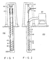
- Figs. 1 and 2 illustrate a first embodiment of the invention.
- rope-like tension members 2 are provided outside a corrugated heat pipe.
- the corrugated heat pipe is made of such metal as steel, copper, aluminum and skinless steel and has an inner diameter of 50 to 300 mm.
- Its peripheral wall 101 is wavy, i. e. corrugated, in the longitudinal direction.
- Corrugated heat pipe 1 as shown has flexibility, and its main portion is inserted substantially vertically in the ground 100 into a depth of 200 to 300 m.
- Rope-like tension members 2 are composed of steel wire stands and extend along the outer peripheral surface of corrugated heat pipe 1 in the longitudinal direction thereof.
- One or more (practically four or more) rope-like tension members 2 are used depending on the size and weight of corrugated heat pipe 1.
- the number of rope-like tension members provided on the outer peripheral surface of corrugated heat pipe 1 and also the number and diameter of stranded wires, are suitably selected depending on desired mechanical strength. Since a plurality of rope-like tension members are provided on the outer peripheral surface of corrugated heat pipe 1, their inspection and maintenance may be readily done even in the event of occurrence of damage to some of them.
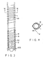
- Reference numeral 18 designates a wire, which is a solid or stranded metal wire. As shown in Fig. 3 it is wound helically and continuously on the outer peripheral surface of corrugated heat pipe 1 over a necessary length thereof at a substantially constant pitch, whereby rope-like tension members 2 are held in close contact with the periphery of pipe 1. Where periphery of corrugated heat pipe 1 is corrugated helically, wire 18 is drawn with tensile force P (as shown in Fig. 4) while adjusting its position such that it is accomodated in helical groove 19 of corrugation at the pitch thereof. The ends of wire 18 thus wound are treated by suitable available means so that the wire will not become loose. Wire 18 may be wound at a constant pitch, i. e., at the same pitch as the pitch of corrugation of the corrugated heat pipe, or the pitch may be reduced so that the wire is wound more closely where the own weight is greatly supported.
- wire 18 may be wound helically, or it may be wound helically in one direction and then in the opposite direction so that it turns overlap. Where corrugated heat pipe 1 has a bellows-like corrugation, wire 18 of course may be wound either helically or non-helically.
- the various components of the corrugated heat pipe may be mounted in factory or in the site of installation.
- a portion of the corrugated heat pipe extending from the ground surface is connected to cooler 20.
- Operating liquid 102 which is sealed under a reduced pressure condition in the corrugated heat pipe (Fig. 3), repeats a cycle of being evaporated by the terrestrial heat to enter cooler 20 and transfer its heat thereto, thus being condensed into liquid to be recirculated to the bottom of the corrugated heat pipe for evaporation again.
- Figs. 5 and 6 illustrate a modification of the corrugated heat pipe shown in Figs. 3 and 4.
- rope-like tension members are held in close contact with corrugated heat pipe 1 by a preformed helical wire. More specifically, like the embodiment of Figs. 1 to 4, performed helical wire 31 in a helical form at a substantially constant pitch and having a suitable length is wound on the outer peripheral surface of corrugated heat pipe 1 as means for holding rope-like tension members 2 extending along the outer periphery of pipe 1 in the longitudinal direction thereof in close contact with pipe 1.
- Preformed helical wire 31 is made of a metal having comparatively high spring characters, e.g., steel or non-ferrous metals or alloys.
- the helical winding of wire 31 has an inner diameter slightly smaller than the outer diameter of corrugated heat pipe 1 inclusive of rope-like tension members 2.
- preformed helical wire 31 when wire 31 is fitted manually, an adequate spring pressure is provided to eliminate slip between rope-like tension member 2 and corrugated heat pipe 1.
- a plurality of preformed helical wires 31 may be used such that they are assembled in advance into a strip-like form. Further, the inner side of the helical winding of wire may be sanded to provide enhanced frictional force. In this case, it is possible to prevent slip between preformed helical wire 31 and corrugated heat pipe 1 and effectively support the weight of the corrugated heat pipe.
- Such preformed helical wire 31 need not be provided over the entire length of pipe 1, but it may be provided on suitable portion of pipe 1 in the longitudinal direction thereof (for instance at a longitudinal interval of 5 m). Thus, preformed helical wire 31 may be readily mounted at the installation site. In this case, the wire may be provided at a constant interval as in the embodiment of Fig. 5, but it may be provided more closely where much weight is supported.
- Preformed helical wire 31 may be suitably provided irrespective of whether the periphery of corrugated heat pipe 1 has a helical or bellows-like corrugation.
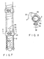
- Figs. 7 and 8 show a modification of a embodiment of Figs. 1 to 4.
- hinged strip-like members are used as means for holding the rope-like tension members in close contact with the corrugated heat pipe.
- corrugated heat pipe 1 is further provided with other, usually used accessory devices, e. g., a terrestrial heat conducting pipe, a liquid return pipe, branch pipes, etc. Further, corrugated heat pipe 1 is supported, if necessary, by an on-ground building structure, and also it may be partly provided with heat insulation, corrosion-proof and other protective treatments.
- accessory devices e. g., a terrestrial heat conducting pipe, a liquid return pipe, branch pipes, etc.
- corrugated heat pipe 1 is supported, if necessary, by an on-ground building structure, and also it may be partly provided with heat insulation, corrosion-proof and other protective treatments.
- the corrugated heat pipe may be installed in the sea, or it may be installed such that it is inclined with respect to the ground surface. For example, when there is an obstacle in the ground, it may be installed in an inclined state to avoid such an obstacle. Further, it may be installed horizontally. If the corrugated heat pipe is installed horizontally, when a force due to longitudinal thermal expansion is exerted, the rope-like tension member has the effect of preventing the corrugated heat pipe from elongating and thus deforming. Thus, it is possible to maintain satisfactory heat transfer characteristics.
- the elongate heat pipe As has been described in the foregoing, according to the invention it is possible to provide an elongate heat pipe, which can be readily transported.
- This elongate heat pipe can preclude low operability works on the installation site.
- the elongate heat pipe may be factory provided with various components. With the functions of these components, it is possible to prevent the pipe from elongating due to the weight thereof, particularly prevent the pipe from crushing due to high radial external pressure applied to its portion extending deep in the ground, and also prevent an upper portion of the pipe from drying owing to positive promotion of evaporation by the liquid condensate receptacle, wick and other parts. Further, on the installation site, it is only necessary to insert and hang the corrugated heat pipe in a pit in the simplest case.
Landscapes
- Engineering & Computer Science (AREA)
- General Engineering & Computer Science (AREA)
- Mechanical Engineering (AREA)
- Physics & Mathematics (AREA)
- Sustainable Development (AREA)
- Life Sciences & Earth Sciences (AREA)
- Thermal Sciences (AREA)
- Sustainable Energy (AREA)
- Chemical & Material Sciences (AREA)
- Combustion & Propulsion (AREA)
- Geometry (AREA)
- Rigid Pipes And Flexible Pipes (AREA)
- Thermal Insulation (AREA)
- Laying Of Electric Cables Or Lines Outside (AREA)
Applications Claiming Priority (6)
| Application Number | Priority Date | Filing Date | Title |
|---|---|---|---|
| JP53975/87 | 1987-03-11 | ||
| JP62053975A JPS63223493A (ja) | 1987-03-11 | 1987-03-11 | コルゲ−ト型ヒ−トパイプ |
| JP86989/87 | 1987-04-10 | ||
| JP62086989A JPS63254393A (ja) | 1987-04-10 | 1987-04-10 | コルゲ−ト型ヒ−トパイプ |
| JP117168/87 | 1987-05-15 | ||
| JP62117168A JPS63282492A (ja) | 1987-05-15 | 1987-05-15 | ヒ−トパイプ |
Related Parent Applications (1)
| Application Number | Title | Priority Date | Filing Date |
|---|---|---|---|
| EP88103921.8 Division | 1988-03-11 |
Publications (2)
| Publication Number | Publication Date |
|---|---|
| EP0400687A1 true EP0400687A1 (fr) | 1990-12-05 |
| EP0400687B1 EP0400687B1 (fr) | 1994-01-19 |
Family
ID=27295130
Family Applications (2)
| Application Number | Title | Priority Date | Filing Date |
|---|---|---|---|
| EP90113175A Expired - Lifetime EP0400687B1 (fr) | 1987-03-11 | 1988-03-11 | Caloduc ondulé |
| EP88103921A Expired - Lifetime EP0282092B1 (fr) | 1987-03-11 | 1988-03-11 | Caloduc ondulé |
Family Applications After (1)
| Application Number | Title | Priority Date | Filing Date |
|---|---|---|---|
| EP88103921A Expired - Lifetime EP0282092B1 (fr) | 1987-03-11 | 1988-03-11 | Caloduc ondulé |
Country Status (4)
| Country | Link |
|---|---|
| US (4) | US4836275A (fr) |
| EP (2) | EP0400687B1 (fr) |
| KR (1) | KR930000658B1 (fr) |
| DE (2) | DE3878703T2 (fr) |
Cited By (2)
| Publication number | Priority date | Publication date | Assignee | Title |
|---|---|---|---|---|
| WO2010147549A1 (fr) * | 2008-11-10 | 2010-12-23 | Pemtec Ab | Systeme permettant l'extraction d'energie a partir du sol |
| US8079420B2 (en) | 2005-05-26 | 2011-12-20 | Pemtec Ab | Sealing device |
Families Citing this family (50)
| Publication number | Priority date | Publication date | Assignee | Title |
|---|---|---|---|---|
| US4930572A (en) * | 1988-09-14 | 1990-06-05 | Doshier John R | Heat pipe and aqua-thaw animal waterer |
| DE3910094A1 (de) * | 1989-03-29 | 1990-10-18 | Gerd Hoermansdoerfer | Spezielles waermerohr |
| US5026209A (en) * | 1989-08-04 | 1991-06-25 | Eau-Viron Incorporated | Containment casing for a deep well gravity pressure reactor vessel |
| US5339890A (en) * | 1993-02-08 | 1994-08-23 | Climate Master, Inc. | Ground source heat pump system comprising modular subterranean heat exchange units with concentric conduits |
| JP2911441B1 (ja) * | 1998-04-03 | 1999-06-23 | 伊藤 さとみ | ヒートパイプ及びその製造方法とそれを用いた放熱構造 |
| US6293332B2 (en) * | 1999-03-31 | 2001-09-25 | Jia Hao Li | Structure of a super-thin heat plate |
| DE10202261A1 (de) * | 2002-01-21 | 2003-08-07 | Waterkotte Waermepumpen Gmbh | Wärmequellen- oder Wärmesenken-Anlage mit thermischer Erdankopplung |
| US6793009B1 (en) * | 2003-06-10 | 2004-09-21 | Thermal Corp. | CTE-matched heat pipe |
| US20050139995A1 (en) * | 2003-06-10 | 2005-06-30 | David Sarraf | CTE-matched heat pipe |
| US20050173098A1 (en) * | 2003-06-10 | 2005-08-11 | Connors Matthew J. | Three dimensional vapor chamber |
| US7401641B1 (en) * | 2004-05-24 | 2008-07-22 | Earth To Air Systems, Llc | Vertically oriented direct exchange/geothermal heating/cooling system sub-surface tubing installation means |
| US7363769B2 (en) * | 2005-03-09 | 2008-04-29 | Kelix Heat Transfer Systems, Llc | Electromagnetic signal transmission/reception tower and accompanying base station employing system of coaxial-flow heat exchanging structures installed in well bores to thermally control the environment housing electronic equipment within the base station |
| US7841383B2 (en) * | 2005-09-30 | 2010-11-30 | Earth To Air Systems, Llc | Encasement assembly for installation of sub-surface refrigerant tubing in a direct exchange heating/cooling system |
| US7621318B2 (en) * | 2006-07-10 | 2009-11-24 | Exxonmobile Research And Engineering Co. | Heat pipe structure |
| US8176972B2 (en) * | 2006-08-31 | 2012-05-15 | International Business Machines Corporation | Compliant vapor chamber chip packaging |
| US10962261B1 (en) | 2006-09-08 | 2021-03-30 | Charles E. Hill | Earth coupled heat exchanger for a geothermal heat pump |
| WO2008039202A1 (fr) * | 2006-09-29 | 2008-04-03 | Earth To Air Systems, Llc | ensemble formant une enveloppe permettant l'installation de tubage rÉfrigÉrant de sub-surface DANS UN SYSTÈME DE CHAUFFAGE / REFROIDISSEMENT À échange direct |
| AU2008206112B2 (en) * | 2007-01-18 | 2012-04-05 | Earth To Air Systems, Llc | Multi-faceted designs for a direct exchange geothermal heating/cooling system |
| US20080253082A1 (en) * | 2007-04-12 | 2008-10-16 | Lev Jeffrey A | Cooling system with flexible heat transport element |
| US8833098B2 (en) * | 2007-07-16 | 2014-09-16 | Earth To Air Systems, Llc | Direct exchange heating/cooling system |
| WO2009049317A2 (fr) * | 2007-10-11 | 2009-04-16 | Earth To Air Systems, Llc | Améliorations de conception de système dx avancée |
| US20090120606A1 (en) * | 2007-11-08 | 2009-05-14 | Earth To Air, Llc | Double DX Hydronic System |
| US8082751B2 (en) * | 2007-11-09 | 2011-12-27 | Earth To Air Systems, Llc | DX system with filtered suction line, low superheat, and oil provisions |
| US8468842B2 (en) * | 2008-04-21 | 2013-06-25 | Earth To Air Systems, Llc | DX system having heat to cool valve |
| US8402780B2 (en) * | 2008-05-02 | 2013-03-26 | Earth To Air Systems, Llc | Oil return for a direct exchange geothermal heat pump |
| US8776543B2 (en) * | 2008-05-14 | 2014-07-15 | Earth To Air Systems, Llc | DX system interior heat exchanger defrost design for heat to cool mode |
| US20100270002A1 (en) * | 2008-08-05 | 2010-10-28 | Parrella Michael J | System and method of maximizing performance of a solid-state closed loop well heat exchanger |
| NZ590335A (en) | 2008-06-13 | 2013-08-30 | Michael J Parrella | System and method of capturing geothermal heat from within a drilled well to generate electricity |
| US9423158B2 (en) * | 2008-08-05 | 2016-08-23 | Michael J. Parrella | System and method of maximizing heat transfer at the bottom of a well using heat conductive components and a predictive model |
| US20100270001A1 (en) * | 2008-08-05 | 2010-10-28 | Parrella Michael J | System and method of maximizing grout heat conductibility and increasing caustic resistance |
| US8534069B2 (en) * | 2008-08-05 | 2013-09-17 | Michael J. Parrella | Control system to manage and optimize a geothermal electric generation system from one or more wells that individually produce heat |
| US20110209848A1 (en) * | 2008-09-24 | 2011-09-01 | Earth To Air Systems, Llc | Heat Transfer Refrigerant Transport Tubing Coatings and Insulation for a Direct Exchange Geothermal Heating/Cooling System and Tubing Spool Core Size |
| US8490703B2 (en) * | 2009-02-12 | 2013-07-23 | Red Leaf Resources, Inc | Corrugated heating conduit and method of using in thermal expansion and subsidence mitigation |
| US9109813B2 (en) * | 2010-02-23 | 2015-08-18 | Robert Jensen | Twisted conduit for geothermal heating and cooling systems |
| US8640765B2 (en) | 2010-02-23 | 2014-02-04 | Robert Jensen | Twisted conduit for geothermal heating and cooling systems |
| US9909783B2 (en) * | 2010-02-23 | 2018-03-06 | Robert Jensen | Twisted conduit for geothermal heat exchange |
| US20110203765A1 (en) * | 2010-02-23 | 2011-08-25 | Robert Jensen | Multipipe conduit for geothermal heating and cooling systems |
| US8997509B1 (en) | 2010-03-10 | 2015-04-07 | B. Ryland Wiggs | Frequent short-cycle zero peak heat pump defroster |
| US9121393B2 (en) | 2010-12-10 | 2015-09-01 | Schwarck Structure, Llc | Passive heat extraction and electricity generation |
| US20130025820A1 (en) * | 2011-07-25 | 2013-01-31 | Tai-Her Yang | Close-loop temperature equalization device having single-flowpathheat releasing device |
| US9200850B2 (en) * | 2011-07-25 | 2015-12-01 | Tai-Her Yang | Closed-loop temperature equalization device having a heat releasing system structured by multiple flowpaths |
| US9291372B2 (en) * | 2011-07-25 | 2016-03-22 | Tai-Her Yang | Closed-loop temperature equalization device having a heat releasing device and multiple flowpaths |
| US20130042997A1 (en) * | 2011-08-15 | 2013-02-21 | Tai-Her Yang | Open-loopnatural thermal energy releasing system wtih partialreflux |
| MX2014001804A (es) | 2011-08-16 | 2014-03-31 | Red Leaf Resources Inc | Dispositivo para la transferencia de fluidos con compactacion vertical. |
| US20160102922A1 (en) * | 2014-10-10 | 2016-04-14 | Richard Curtis Bourne | Packaged Helical Heat Exchanger |
| US10988904B2 (en) * | 2016-08-18 | 2021-04-27 | Ian R. Cooke | Snow and ice melting device, system and corresponding methods |
| CN106225512A (zh) * | 2016-09-23 | 2016-12-14 | 四川大学 | 一种结合桩基换热埋管的预制结构柱 |
| CN109798793B (zh) * | 2018-12-25 | 2024-06-04 | 河北工程大学 | 一种用于煤矸石山深度移热的热管装置 |
| CN113566626A (zh) * | 2020-12-25 | 2021-10-29 | 昆山同川铜业科技有限公司 | 一种多尺度毛细吸液芯编织网 |
| US11913678B2 (en) * | 2021-09-03 | 2024-02-27 | Richard Curtis Bourne | Ground heat-exchange system with water-filled boreholes |
Citations (2)
| Publication number | Priority date | Publication date | Assignee | Title |
|---|---|---|---|---|
| US4090555A (en) * | 1974-04-22 | 1978-05-23 | Mcdonnell Douglas Corporation | Heat pipe assembly |
| US4402358A (en) * | 1982-10-15 | 1983-09-06 | The United States Of America As Represented By The Administrator Of The National Aeronautics And Space Administration | Heat pipe thermal switch |
Family Cites Families (9)
| Publication number | Priority date | Publication date | Assignee | Title |
|---|---|---|---|---|
| US2066794A (en) * | 1935-08-07 | 1937-01-05 | Ingersoll Rand Co | Drill stem |
| US3604503A (en) * | 1968-08-02 | 1971-09-14 | Energy Conversion Systems Inc | Heat pipes |
| US3935900A (en) * | 1971-08-25 | 1976-02-03 | Mcdonnell Douglas Corporation | Permafrost structural support with integral heat pipe means |
| DE2913472A1 (de) * | 1979-04-04 | 1980-10-16 | Daimler Benz Ag | Waermerohr grosser laenge |
| US4326586A (en) * | 1980-07-03 | 1982-04-27 | Standard Oil Company (Indiana) | Method for stressing thermal well casings |
| JPS5888593A (ja) * | 1981-11-20 | 1983-05-26 | Hisateru Akachi | ヒ−トパイプ放熱器 |
| JPS5935785A (ja) * | 1982-08-20 | 1984-02-27 | Fujikura Ltd | ヒ−トパイプ |
| JPS5977292A (ja) * | 1982-10-25 | 1984-05-02 | Nippon Buroaa Kk | 可撓性ヒ−トパイプ |
| SU1108323A1 (ru) * | 1983-02-07 | 1984-08-15 | Рязанский Радиотехнический Институт | Теплова труба |
-
1988
- 1988-03-07 US US07/164,560 patent/US4836275A/en not_active Expired - Fee Related
- 1988-03-09 KR KR1019880002441A patent/KR930000658B1/ko not_active Expired - Fee Related
- 1988-03-11 DE DE88103921T patent/DE3878703T2/de not_active Expired - Fee Related
- 1988-03-11 EP EP90113175A patent/EP0400687B1/fr not_active Expired - Lifetime
- 1988-03-11 DE DE3887349T patent/DE3887349T2/de not_active Expired - Fee Related
- 1988-03-11 EP EP88103921A patent/EP0282092B1/fr not_active Expired - Lifetime
-
1989
- 1989-01-26 US US07/302,404 patent/US4858679A/en not_active Expired - Fee Related
- 1989-01-26 US US07/302,624 patent/US4917175A/en not_active Expired - Fee Related
- 1989-01-26 US US07/302,764 patent/US4854372A/en not_active Expired - Fee Related
Patent Citations (2)
| Publication number | Priority date | Publication date | Assignee | Title |
|---|---|---|---|---|
| US4090555A (en) * | 1974-04-22 | 1978-05-23 | Mcdonnell Douglas Corporation | Heat pipe assembly |
| US4402358A (en) * | 1982-10-15 | 1983-09-06 | The United States Of America As Represented By The Administrator Of The National Aeronautics And Space Administration | Heat pipe thermal switch |
Cited By (2)
| Publication number | Priority date | Publication date | Assignee | Title |
|---|---|---|---|---|
| US8079420B2 (en) | 2005-05-26 | 2011-12-20 | Pemtec Ab | Sealing device |
| WO2010147549A1 (fr) * | 2008-11-10 | 2010-12-23 | Pemtec Ab | Systeme permettant l'extraction d'energie a partir du sol |
Also Published As
| Publication number | Publication date |
|---|---|
| DE3878703T2 (de) | 1993-09-30 |
| US4836275A (en) | 1989-06-06 |
| EP0282092A2 (fr) | 1988-09-14 |
| EP0400687B1 (fr) | 1994-01-19 |
| EP0282092A3 (en) | 1988-12-14 |
| KR930000658B1 (ko) | 1993-01-29 |
| US4917175A (en) | 1990-04-17 |
| EP0282092B1 (fr) | 1993-03-03 |
| DE3878703D1 (de) | 1993-04-08 |
| DE3887349T2 (de) | 1994-09-01 |
| US4858679A (en) | 1989-08-22 |
| KR880011513A (ko) | 1988-10-28 |
| US4854372A (en) | 1989-08-08 |
| DE3887349D1 (de) | 1994-03-03 |
Similar Documents
| Publication | Publication Date | Title |
|---|---|---|
| EP0400687A1 (fr) | Caloduc ondulé | |
| US6224025B1 (en) | Snap-on/twist-in pipe saddle and installation method | |
| US7381900B2 (en) | Power cable for direct electric heating system | |
| US4401156A (en) | Heat transfer apparatus for releasably securing heating or cooling means to pipe | |
| EP1686301B1 (fr) | Profilé de protection pour câble sous-marin | |
| US4564061A (en) | Cooling system for communications devices with high power losses | |
| EP0021597A2 (fr) | Dispositif de transfert de chaleur permettant de fixer de façon amovible des moyens chauffants ou réfrigérants sur un tube | |
| US6000187A (en) | Connection structure and connector means for a cable/pipe bed | |
| SE9502861L (sv) | Värmeisolerat rörledninssystem, förfarande för utläggning av rören samt anordning för förbindning av rören | |
| KR102098382B1 (ko) | 배전선로의 절연성 연결대 | |
| JPH0789690B2 (ja) | 極低温ケーブルの布設方法 | |
| CN210053143U (zh) | 一种电力线路结构 | |
| JPH0542203Y2 (fr) | ||
| CN222147083U (zh) | 一种弯角结构电缆保护管 | |
| CN217769359U (zh) | 一种高强度室外弱电管道 | |
| JPS6353769B2 (fr) | ||
| KR930000660B1 (ko) | 파상형(Corrugate) 열 파이프 | |
| JPH054594B2 (fr) | ||
| JPS5850486B2 (ja) | ケ−ブル布設方法 | |
| JPH054595B2 (fr) | ||
| AU714700B2 (en) | Protection of pipelines | |
| JPS63223493A (ja) | コルゲ−ト型ヒ−トパイプ | |
| JPH0652019B2 (ja) | 鉄塔融雪装置 | |
| JPS63202214A (ja) | 電線ケ−ブルの貫通装置 | |
| JPS63209418A (ja) | 電線ケ−ブルの貫通装置 |
Legal Events
| Date | Code | Title | Description |
|---|---|---|---|
| PUAI | Public reference made under article 153(3) epc to a published international application that has entered the european phase |
Free format text: ORIGINAL CODE: 0009012 |
|
| 17P | Request for examination filed |
Effective date: 19900710 |
|
| AC | Divisional application: reference to earlier application |
Ref document number: 282092 Country of ref document: EP |
|
| AK | Designated contracting states |
Kind code of ref document: A1 Designated state(s): DE FR GB |
|
| 17Q | First examination report despatched |
Effective date: 19920227 |
|
| GRAA | (expected) grant |
Free format text: ORIGINAL CODE: 0009210 |
|
| AC | Divisional application: reference to earlier application |
Ref document number: 282092 Country of ref document: EP |
|
| AK | Designated contracting states |
Kind code of ref document: B1 Designated state(s): DE FR GB |
|
| REF | Corresponds to: |
Ref document number: 3887349 Country of ref document: DE Date of ref document: 19940303 |
|
| ET | Fr: translation filed | ||
| PLBE | No opposition filed within time limit |
Free format text: ORIGINAL CODE: 0009261 |
|
| STAA | Information on the status of an ep patent application or granted ep patent |
Free format text: STATUS: NO OPPOSITION FILED WITHIN TIME LIMIT |
|
| 26N | No opposition filed | ||
| PGFP | Annual fee paid to national office [announced via postgrant information from national office to epo] |
Ref country code: GB Payment date: 19980303 Year of fee payment: 11 |
|
| PGFP | Annual fee paid to national office [announced via postgrant information from national office to epo] |
Ref country code: FR Payment date: 19980310 Year of fee payment: 11 |
|
| PGFP | Annual fee paid to national office [announced via postgrant information from national office to epo] |
Ref country code: DE Payment date: 19980429 Year of fee payment: 11 |
|
| PG25 | Lapsed in a contracting state [announced via postgrant information from national office to epo] |
Ref country code: GB Free format text: LAPSE BECAUSE OF NON-PAYMENT OF DUE FEES Effective date: 19990311 |
|
| GBPC | Gb: european patent ceased through non-payment of renewal fee |
Effective date: 19990311 |
|
| PG25 | Lapsed in a contracting state [announced via postgrant information from national office to epo] |
Ref country code: FR Free format text: LAPSE BECAUSE OF NON-PAYMENT OF DUE FEES Effective date: 19991130 |
|
| REG | Reference to a national code |
Ref country code: FR Ref legal event code: ST |
|
| PG25 | Lapsed in a contracting state [announced via postgrant information from national office to epo] |
Ref country code: DE Free format text: LAPSE BECAUSE OF NON-PAYMENT OF DUE FEES Effective date: 20000101 |