EP0400708B1 - Cuillère-doseuse pliable - Google Patents
Cuillère-doseuse pliable Download PDFInfo
- Publication number
- EP0400708B1 EP0400708B1 EP19900201257 EP90201257A EP0400708B1 EP 0400708 B1 EP0400708 B1 EP 0400708B1 EP 19900201257 EP19900201257 EP 19900201257 EP 90201257 A EP90201257 A EP 90201257A EP 0400708 B1 EP0400708 B1 EP 0400708B1
- Authority
- EP
- European Patent Office
- Prior art keywords
- packaging
- carrier ring
- scoop portion
- measuring spoon
- scoop
- Prior art date
- Legal status (The legal status is an assumption and is not a legal conclusion. Google has not performed a legal analysis and makes no representation as to the accuracy of the status listed.)
- Expired - Lifetime
Links
- 238000004806 packaging method and process Methods 0.000 claims description 46
- 230000002093 peripheral effect Effects 0.000 claims description 24
- 239000000463 material Substances 0.000 claims description 23
- 239000011888 foil Substances 0.000 claims description 13
- 229910052751 metal Inorganic materials 0.000 claims description 4
- 239000002184 metal Substances 0.000 claims description 4
- 230000008878 coupling Effects 0.000 claims description 2
- 238000010168 coupling process Methods 0.000 claims description 2
- 238000005859 coupling reaction Methods 0.000 claims description 2
- 238000001746 injection moulding Methods 0.000 description 5
- 238000004519 manufacturing process Methods 0.000 description 5
- 230000002349 favourable effect Effects 0.000 description 2
- 239000011521 glass Substances 0.000 description 2
- 238000007493 shaping process Methods 0.000 description 2
- 241001122767 Theaceae Species 0.000 description 1
- 239000000853 adhesive Substances 0.000 description 1
- 238000004026 adhesive bonding Methods 0.000 description 1
- 230000001070 adhesive effect Effects 0.000 description 1
- 239000004411 aluminium Substances 0.000 description 1
- 229910052782 aluminium Inorganic materials 0.000 description 1
- XAGFODPZIPBFFR-UHFFFAOYSA-N aluminium Chemical compound [Al] XAGFODPZIPBFFR-UHFFFAOYSA-N 0.000 description 1
- 238000009954 braiding Methods 0.000 description 1
- 235000020152 coffee milk drink Nutrition 0.000 description 1
- 238000010276 construction Methods 0.000 description 1
- 239000000945 filler Substances 0.000 description 1
- 230000006870 function Effects 0.000 description 1
- 238000010438 heat treatment Methods 0.000 description 1
- 238000000465 moulding Methods 0.000 description 1
- 239000005022 packaging material Substances 0.000 description 1
- 239000002245 particle Substances 0.000 description 1
- 238000003825 pressing Methods 0.000 description 1
- 238000007665 sagging Methods 0.000 description 1
- 235000014347 soups Nutrition 0.000 description 1
- 230000002459 sustained effect Effects 0.000 description 1
- XLYOFNOQVPJJNP-UHFFFAOYSA-N water Substances O XLYOFNOQVPJJNP-UHFFFAOYSA-N 0.000 description 1
Images



Classifications
-
- A—HUMAN NECESSITIES
- A47—FURNITURE; DOMESTIC ARTICLES OR APPLIANCES; COFFEE MILLS; SPICE MILLS; SUCTION CLEANERS IN GENERAL
- A47G—HOUSEHOLD OR TABLE EQUIPMENT
- A47G21/00—Table-ware
- A47G21/04—Spoons; Pastry servers
-
- B—PERFORMING OPERATIONS; TRANSPORTING
- B65—CONVEYING; PACKING; STORING; HANDLING THIN OR FILAMENTARY MATERIAL
- B65D—CONTAINERS FOR STORAGE OR TRANSPORT OF ARTICLES OR MATERIALS, e.g. BAGS, BARRELS, BOTTLES, BOXES, CANS, CARTONS, CRATES, DRUMS, JARS, TANKS, HOPPERS, FORWARDING CONTAINERS; ACCESSORIES, CLOSURES, OR FITTINGS THEREFOR; PACKAGING ELEMENTS; PACKAGES
- B65D51/00—Closures not otherwise provided for
- B65D51/24—Closures not otherwise provided for combined or co-operating with auxiliary devices for non-closing purposes
- B65D51/246—Closures not otherwise provided for combined or co-operating with auxiliary devices for non-closing purposes provided with eating utensils or spatulas
- B65D51/247—Closures not otherwise provided for combined or co-operating with auxiliary devices for non-closing purposes provided with eating utensils or spatulas located between an inner and an outer closure
-
- G—PHYSICS
- G01—MEASURING; TESTING
- G01F—MEASURING VOLUME, VOLUME FLOW, MASS FLOW OR LIQUID LEVEL; METERING BY VOLUME
- G01F19/00—Calibrated capacity measures for fluids or fluent solid material, e.g. measuring cups
- G01F19/002—Measuring spoons or scoops
Definitions
- the present invention relates to a packaging which consists of a holder with an opening which prior to use of the contents is closed with a removable tagger, and a cover which after removal of the tagger takes over the function of closing the holder opening and further protects the tagger against damage.
- Such a packaging is often used for packaging material in particle form, particularly foodstuffs, such as coffee milk, powdered soup and the like.
- the packaging can consist of a metal holder, a glass holder, a plastic holder and the like.
- a measuring spoon is often supplied with this packaging.
- the measuring spoon is often arranged in the holder. This means that after breaking open the packaging the measuring spoon is buried under the contents of the packaging and is only found after the consumer has rummaged through the contents.
- GB-A-2 052 246 discloses a spoon comprising a handle and a spoon portion, which curved spoon portion is formed by folding a handle forming sheet along folding lines.
- the preamble of claim 1 is based on GB-A-2 052 246.
- the present invention has for its object to incorporate the measuring spoon in the packaging in an entirely different manner, and this in the space lying between the cover and the tagger.
- the measuring spoon is thus directly available to the consumer before the tagger is removed.
- the measuring spoon cannot however be readily arranged into this disc-shaped space, because the scoop portion in particular of the measuring spoon has to have a relatively large capacity (about 10-100 ml) so that the scoop portion is of too large dimensions to be arranged in this disc-shaped space.
- the invention is based on the insight that, despite the small space that is present between the tagger and the cover, a measuring spoon can nevertheless be arranged therein, without providing the tagger or the cover with bulges, by making use of a folding scoop portion which, after folding is coupled to and carried by a carrier ring which is connected to a handle.
- the flat folding measuring spoon according to the invention is therefore characterized in that the spoon portion comprises a carrier ring intended for accomodating the scoop portion.
- a packaging according to the invention is characterized by a folded measuring spoon which resides in the space between the cover and the tagger.
- the handle with the carrier ring spans the opening and supports on an opening rim via the tagger.
- This opening rim can be an edge of a cover ring, or a neck edge of a glass holder. Any forces exerted by the flat-folded scoop portion are sustained via the handle and the carrier ring on the opening rim, so that the tagger cannot be penetrated there.
- a particularly favorable measuring spoon which does not have the problem of components thereof disappearing, results when the handle, the carrier ring and the scoop portion are preferably manufactured from one piece.
- a very convenient packaging results if the measuring spoon is fixed in the cover. It is thus possible for the supplier of the packaging to arrange the tagger and the cover, wherein the measuring spoon is already incorporated, onto the bottomless holder with existing apparatus. The filler finally carries out the filling and subsequently arranges the bottom.
- Such a cover with measuring spoon can be manufactured in only a small number of manufacturing operations, for example injection molding operations, if the cover and the handle with the carrier ring are manufactured from one piece. Only one manufacturing operation is necessary if, as preferred, the cover and the measuring spoon are manufactured from one piece.
- a most advantageous embodiment of the folding measuring spoon according to the invention results if in preference the scoop portion is a circle segment-shaped strip of material which can be folded to form a cone. If a recess is arranged in the strip of material at the point of the centre of the circle, the cone can easily be formed by folding, while the hole created in the measuring spoon in the apex angle of the cone allows substantially no material through because of the mutual material cohesion, while emptying material from the measuring scoop is facilitated.
- the folded form of the measuring scoop can be locked if along the curved peripheral edge of the strip of material at least one protruding edge portion is preferably arranged which, after forming of the strip of material into a cone, can be hooked behind the carrier ring. This is important if the measuring scoop in the folded form is manufactured for instance by injection molding, because material stress results in the flat-folded form, which is removed when the measuring spoon form is assumed. In this way the forming of the measuring spoon from the flat-folded form is easy and substantially self-explanatory.
- the scoop portion comprises a scoop portion bottom having peripheral wall parts connected thereto via folding edges.
- handle with carrier ring and scoop portion are inseparably connected if in preference one peripheral wall part is connected to the carrier ring.
- the measuring spoon form can also be locked in this case if at least one peripheral wall part is preferably provided with a protruding edge portion hookable behind the carrier ring.
- a very advantageous form which is recognizable to the consumer and is easily folded into the measuring spoon, results if the peripheral wall parts in the flat-folded form preferably protrude radially in a star shape.
- Another embodiment of the packaging according to the invention has a measuring spoon in which the scoop portion comprises a bottom part and optionally at least one intermediate clamp part, which are mutually clamped via a peripheral edge during forming of the scoop portion.
- the measuring spoon results from so-called clamping nesting of the bottom part and any intermediate clamp parts in each other and in the peripheral edge of the carrier ring.
- the bottom, the intermediate clamp part and the carrier ring are preferably connected mutually via flexible strips, whereby all the components of the measuring spoon are non-losably connected to each other.
- a measuring spoon is used in which the scoop portion comprises a foil attached to the carrier ring and means for forming the foil to the scoop portion.
- the scoop portion is formed by a foil for shaping which is brought into and kept in the form of the scoop portion.
- these forming means comprise brackets of memory metal fixed to the carrier ring.
- the forming means comprise a scoop portion bottom and at least one strip coupling the scoop portion bottom to the carrier ring.
- the foil is arranged between the carrier ring and the scoop portion bottom, and the scoop portion bottom can be arranged in the carrier ring, whereby a measuring scoop results with a scoop portion bottom that can sag downward.
- an equivalent of a tea strainer can be used as measuring scoop, because when there are many materials to be measured out the mutual cohesion is such that the material cannot leave the measuring scoop through small openings.
- This variant comprises a scoop portion with a braiding of strips of material which are connected to the carrier ring.
- the scoop portion comprises a bottom which is connected to the carrier ring via a peripheral edge, wherein a large number of slits are arranged lying transversely of the carrier ring, whereby flexible peripheral wall strips are formed.
- the invention not only relates to the measuring spoon and the packaging with a folding measuring scoop according to the invention, but also to a cover wherein this measuring spoon is fixed, for instance by glueing, or by moulding in a simultaneous manufacturing operation, such as for instance by injection molding.
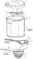
- Figure 1 shows a packaging 1 according to the invention which comprises a cylindrical, metal holder 2 with an end opening 3 which is closed off with an aluminium tagger 4 that is a conventional tagger.
- This tagger rests on a holder rim 5 bent round towards the inside.
- the tagger 4 and after removal the opening 3 can be closed with a plastic cover 6, which can be arranged closing over the holder 2, wherein an internal peripheral edge 7 of the cover 6 snaps over an external rim 8 of the holder.
- This measuring spoon 9 Arranged in the disc-shaped space between the cover 6 and the tagger 4 is a folded measuring spoon 9 according to the invention.
- This measuring spoon 9 comprises a stiff handle 10 with a carrier ring 11 and a scoop portion 12 folded out thereon.
- This scoop portion 12 is folded such that it lies between the cover and the handle 10 with carrier ring 11, which support on the holder rim 5. Damage to the tagger 4 is thus avoided, even when the folded scoop portion is under shaping bias.
- the construction and manufacture of the measuring spoon 9 is shown in more detail in figures 2-4.
- the scoop portion 12 comprises a circle segment-shaped strip of material 13 with a recess 14 at the point of an imaginary centre point. Forming into a conical scoop portion 12 is thus made easier.
- protruding edge portions 16 are arranged along the curved peripheral edge of the strip of material 13, which, after folding to the measuring scoop, hook onto the carrier ring 11.
- Folding takes place by pressing the strip of material 13 from the position in figure 2 through the carrier ring 11 into the position shown in figure 3.
- a measuring spoon 9 With a capacity of 5-20 ml.
- the measuring spoon In order to facilitate manufacture of the measuring spoon, it can be manufactured for instance by means of injection molding in the state which is shown in figure 4.
- the handle 10, the carrier ring 11 and the conically shaped strip of material 13 with its lengthwise slit 17, are manufactured in one piece and mutually connected via the strip 18.
- Figure 5 shows a variant wherein the measuring spoon 9 forms one entity with the cover 19, in this case a screw cover.
- the measuring spoon 9 lies in folded state wholly within the space which is enclosed by the cover rim 20.
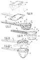
- Figures 6 and 7 show a measuring spoon 21 according to the invention.
- the polygonal carrier ring 22 is connected via a strip 23 to one of the peripheral wall parts 24, 25 which are connected to a scoop portion bottom 27 via straight folding edges 26, which are required for tension-free folding.
- the peripheral wall parts 25 are each provided with a protruding edge portion 28 which hooks onto the carrier ring 22 after the measuring spoon according to figure 7 has been formed.
- Figures 8 and 9 show another packaging 29 according to the invention with a folding measuring spoon 30.
- the scoop portion 31 comprises a square scoop portion bottom 32 and four peripheral wall parts 34, whereof the part 34 is connected via the strip 23 to the circular carrier ring 11.
- the scoop portion 31 hooks onto the carrier ring 11 with a protruding edge portion 35.
- Figures 10 and 11 show a measuring spoon 36 with a handle 37 and carrier ring 38.
- the carrier ring 38 is connected to the scoop portion bottom 39 via a foil 40 and flexible strips 41, so that this concentric scoop portion bottom can be folded into the carrier ring 38.
- the measuring spoon 42 shown in figures 12 and 13 comprises a sack-like foil 43 arranged on the carrier ring 38, and forming means which in this case consist of a scoop portion bottom 44 which is connected to the carrier ring 38 via a flexible strip of material 45. Two other forming strips 46 hold the scoop portion bottom 44 in the bottom of the foil 43 and thus form the scoop portion.
- Figure 12 shows the measuring spoon 42 which is fixed in a cover 48 via adhesive points 47.
- Figures 14 and 15 show a measuring spoon 49 with a handle 50 and a carrier ring 51 as well as a scoop portion 52 consisting of a bottom 53 and a peripheral wall 54, wherein a large number of slits 55 are arranged, whereby during folding flexible peripheral wall strips 56 result.
- the measuring spoon 57 of figure 16 comprises a handle 58 and a rectangular carrier ring 59, wherein a separately folding scoop portion 60 can be arranged that hooks with protruding edges 61 into slots 62 of the carrier ring 59.
- the measuring spoon 57 is a measuring spoon which can easily be formed through folding by a consumer without much insight.
- the measuring spoon 80 comprises a handle 81 with a carrier ring 83 which, with an intermediate ring 84 and bottom ring 85 nesting therein, form the scoop portion 82.
- the carrier ring 83 is connected to the intermediate ring 84 via the flexible strip 86.
- the intermediate ring 84 is connected to the bottom ring 85 via the flexible strip 87.
- the measuring spoon 63 from figure 18 comprises a handle 64 with a carrier ring 65, with a sack-like foil 66 which is held in a scoop portion form by a bottom 67 which is held at a distance from the carrier by way of the strips 68 and 69, whereof the strip 68 os connected to the carrier ring and the strip 69 is hookable thereon.
- the measuring spoon 70 shown in figures 19 and 20 comprises a handle 71 and a carrier ring 72 which is again provided with a sack-like foil 73 which is held in a scoop portion form with wires of memory material which after heating with for instance hot water assume a bracket shape and tighten the foil into the scoop portion form.
- figure 21 shows a measuring spoon 75 with a handle 76 and a carrier ring 77 whereto braided strips 78 and 79 are attached which are flexible and foldable inside the carrier ring 77.
Landscapes
- Engineering & Computer Science (AREA)
- Mechanical Engineering (AREA)
- Physics & Mathematics (AREA)
- Fluid Mechanics (AREA)
- General Physics & Mathematics (AREA)
- Details Of Rigid Or Semi-Rigid Containers (AREA)
- Closures For Containers (AREA)
Claims (24)
- Cuillère doseuse-pliable à plat (9, 21, 30, 36, 42, 49, 57, 63, 70, 75, 80) comprenant un manche (10, 37, 50, 58, 64, 71, 75, 76, 81) et une partie cuillère dans laquelle la partie cuillère est constituée par une partie cuillère pliable à plat (12, 31, 52, 60,82 ) caractérisée en ce que la partie cuillère comprend en outre un anneau support (11, 22, 38, 51, 59, 65, 72, 77, 83) destiné à recevoir la partie cuillère (12, 31, 52, 60, 82).
- Emballage (1, 29) comprenant un contenant (2) avec une ouverture (3) qui peut être fermée par un couvercle (6) et qui est fermée par une capsule amovible (4), caractérisé par une cuillère-doseuse pliée (9,21,30, 36, 42, 49, 57, 63, 70, 75, 80) selon la revendication 1, qui se place dans l'espace situé entre le couvercle (6, 48) et la capsule (4).
- Emballage (1) selon la revendication 2, dans lequel le manche (10) avec l'anneau support (11) est placé en travers de l'ouverture (3) et s'appuie par l'intermédiaire de la capsule (4) sur un bord d'ouverture (8).
- Emballage (1, 29) selon la revendication 2 ou 3, dans lequel le manche (10), l'anneau support (11) et la partie cuillère (12, 31) sont fabriqués en une seule pièce.
- Emballage (1) selon les revendications 2 à 4, dans lequel la cuillère-doseuse (9) est solidaire du couvercle (19).
- Emballage (1) selon la revendication 5, dans lequel le couvercle (19) et le manche (10) avec l'anneau support (11) sont fabriqués en une seule pièce.
- Emballage (1) selon la revendication 6, dans lequel le couvercle (19) et la cuillère-doseuse (9) sont fabriqués en une seule pièce.
- Emballage (1) selon les revendications 2 à 7, dans lequel la partie cuillère (12) est une bande en forme de cercle segmentée en matériau (13) pliable en un cône.
- Emballage (1) selon la revendication 7, dans lequel un évidement (14) est formé dans la bande de matériau (13) à l'endroit du centre du cercle.
- Emballage (1, 29) selon la revendication 8 ou 9, dans lequel la bande de matériau (13) est reliée à l'anneau support (11) par une languette souple (18, 23).
- Emballage (1, 29) selon les revendications 8 à 10, dans lequel le long du bord périphérique courbe de la bande de matériau (13) au moins une partie (16, 35) de bord en saillie est prévue pour s'accrocher derrière l'anneau support (11) lorsque la bande de matériau (13) a été mise en forme de cône.
- Emballage (1, 29) selon les revendications 2 à 7, dans lequel la partie cuillère (12, 31) comprend un fond (27 ; 32) de partie cuillère ayant des parties (24, 25 ; 34) de paroi périphérique reliées à ce fond par des bords pliants (26).
- Emballage (1) selon la revendication 12, dans lequel la partie ( 254; 34) de paroi périphérique est reliée à l'anneau support (22 ; 11).
- Emballage (1) selon la revendication 12 ou 13, dans lequel une partie (25) au moins de paroi périphérique est formée avec une partie (28) de bord en saillie pour s'accrocher derrière l'anneau support (22).
- Emballage (1) selon la revendication 13 ou 14, dans lequel les parties (24, 25) de paroi périphérique font saillie dans la direction radiale pour former une étoile dans la forme pliée à plat.
- Emballage (29) selon les revendications 2 à 7, dans lequel la partie cuillère (82) comprend une partie de fond (39, 44, 85) et, en option, au moins une partie (41, 84) d'accrochage intermédiaire, qui peuvent être accrochées mutuellement au moyen d'un bord périphérique pendant la formation de la partie cuillère (82).
- Emballage (29) selon la revendication 16, dans lequel le fond (85), la partie (84) d'accrochage intermédiaire et l'anneau support (83) sont mutuellement reliés par des languettes souples (86, 87).
- Emballage (1) selon les revendications 2 à 7, dans lequel la partie cuillère comprend une feuille (40, 43, 66, 73) fixée sur l'anneau support (38, 72) et des moyens pour donner à la feuille (40, 43, 66, 73) la forme d'une partie cuillère (44).
- Emballage (1) selon la revendication 18, dans lequel les moyens de mise en forme comprennent des crochets (74) en métal à mémoire fixés à l'anneau support (72).
- Emballage selon la revendication 18, dans lequel les moyens de mise en forme comprennent un fond (39, 44, 67) de partie cuillère et au moins une languette (41 ; 45; 46 ; 68, 69) accouplant le fond (39, 44) de la partie cuillère à l'anneau support (38)
- Emballage selon la revendication 20, dans lequel la feuille (43) est disposée entre l'anneau support (38) et le fond (44) de la partie cuillère et le fond (44) de la partie cuillère peut être remonté à l'intérieur de l'anneau support (38).
- Emballage (1) selon les revendications 2 à 7, dans lequel la partie cuillère est formée de bandes tressées (78, 79) en matériau qui sont reliées à l'anneau support (77).
- Emballage (1) selon les revendications 2 à 7, dans lequel la partie cuillère (52) comprend un fond (53) qui est relié à l'anneau support (51) par un bord périphérique, dans lequel un grand nombre de fentes (55) sont pratiquées dans la direction transversale de l'anneau support (51) de façon à former des bandes souples (56) de paroi périphérique.
- Couvercle (6, 48) prévu pour une cuillère-doseuse (9, 42) selon la revendication 1, destiné à être utilisé dans un emballage selon les revendications 2 à 23.
Applications Claiming Priority (2)
| Application Number | Priority Date | Filing Date | Title |
|---|---|---|---|
| NL8901356A NL8901356A (nl) | 1989-05-29 | 1989-05-29 | Verpakking met een opgevouwen maatlepel, de maatlepel en een deksel voorzien van een dergelijke maatlepel. |
| NL8901356 | 1989-05-29 |
Publications (2)
| Publication Number | Publication Date |
|---|---|
| EP0400708A1 EP0400708A1 (fr) | 1990-12-05 |
| EP0400708B1 true EP0400708B1 (fr) | 1993-12-15 |
Family
ID=19854735
Family Applications (1)
| Application Number | Title | Priority Date | Filing Date |
|---|---|---|---|
| EP19900201257 Expired - Lifetime EP0400708B1 (fr) | 1989-05-29 | 1990-05-17 | Cuillère-doseuse pliable |
Country Status (4)
| Country | Link |
|---|---|
| EP (1) | EP0400708B1 (fr) |
| DE (1) | DE69005197T2 (fr) |
| IE (1) | IE63915B1 (fr) |
| NL (1) | NL8901356A (fr) |
Families Citing this family (13)
| Publication number | Priority date | Publication date | Assignee | Title |
|---|---|---|---|---|
| FR2673606A1 (fr) * | 1991-03-08 | 1992-09-11 | Langevin Jacques | Dispositif pour consommer ou utiliser immediatement un produit tel que fourni par le producteur, sans necessite de recourir a des intermediaires instrumentaux exterieurs. |
| DE69122236T2 (de) * | 1991-06-11 | 1997-02-06 | Thomassen & Drijver | Behälter mit gefaltetem Messlöffel sowie Messlöfel und Deckel mit einem solchen Messlöffel |
| ES1025701Y (es) * | 1993-09-09 | 1994-07-16 | Campos Javier Michelena | Cuchara monouso |
| EP0687637A1 (fr) * | 1994-06-17 | 1995-12-20 | The Procter & Gamble Company | Ensemble de conditionnement |
| FR2709653B1 (fr) * | 1994-07-08 | 1996-08-30 | Comercial Mertapa | Cuillère à usage unique. |
| AUPN098995A0 (en) * | 1995-02-09 | 1995-03-09 | Kohorn International Pty. Ltd. | A container |
| GB2331060B (en) * | 1997-11-07 | 2002-02-27 | Huang Shou Li | Food container cover with retained eating utensil |
| DE29913767U1 (de) * | 1999-08-06 | 1999-12-30 | 4P Verpackungen Ronsberg GmbH, 87671 Ronsberg | Verpackung für wenigstens zwei unterschiedliche Produkte |
| CN100469666C (zh) * | 2002-11-29 | 2009-03-18 | 梁定超 | 内置方便盛物装置的罐盒 |
| UA72910U (ru) * | 2012-06-06 | 2012-08-27 | Приватное Предприятие "Пластко" | Крышка для укупорки емкости |
| ES2541813B1 (es) * | 2015-03-05 | 2016-04-13 | Flaps Comercial, S.L. | Accesorio para envases que incorpora un utensilio desechable |
| CN106144133A (zh) * | 2016-08-30 | 2016-11-23 | 上海大学 | 组合式酸奶包装容器 |
| CN110065705A (zh) * | 2019-04-11 | 2019-07-30 | 傲毅高新材料(无锡)有限公司 | 一种无毒无菌环保型的食用蛋糕包装盒 |
Family Cites Families (3)
| Publication number | Priority date | Publication date | Assignee | Title |
|---|---|---|---|---|
| GB2052246A (en) * | 1979-06-12 | 1981-01-28 | Clark W | Spoons, spatulas, pourers etc. |
| BR8502475A (pt) * | 1984-06-13 | 1986-01-28 | Eduardo Maria Olavarria | Suporte aplicavel a vasilhames descartaveis para sustentar utensilios para o consumo do conteudo |
| NL8601653A (nl) * | 1986-06-24 | 1988-01-18 | Thomassen & Drijver | Houder met een lepel. |
-
1989
- 1989-05-29 NL NL8901356A patent/NL8901356A/nl not_active Application Discontinuation
-
1990
- 1990-05-17 EP EP19900201257 patent/EP0400708B1/fr not_active Expired - Lifetime
- 1990-05-17 DE DE1990605197 patent/DE69005197T2/de not_active Expired - Fee Related
- 1990-05-23 IE IE186890A patent/IE63915B1/en not_active IP Right Cessation
Also Published As
| Publication number | Publication date |
|---|---|
| NL8901356A (nl) | 1990-12-17 |
| IE63915B1 (en) | 1995-06-14 |
| DE69005197T2 (de) | 1994-03-31 |
| IE901868L (en) | 1990-11-29 |
| EP0400708A1 (fr) | 1990-12-05 |
| DE69005197D1 (de) | 1994-01-27 |
Similar Documents
| Publication | Publication Date | Title |
|---|---|---|
| EP0400708B1 (fr) | Cuillère-doseuse pliable | |
| US5235782A (en) | Cover for potted plants and method for covering potted plants | |
| US4801014A (en) | Bouquet sleeve | |
| US4715271A (en) | Disposable beverage brewer | |
| US4735340A (en) | Trash bag bracket | |
| US3334574A (en) | Cup mounted coffee cones | |
| US5267644A (en) | Tuckable carrier means for handling portable container | |
| JP5583427B2 (ja) | 特に固形状またはペースト状の製品用の容器、その製造方法、およびこの容器とそれを受け入れる入れ物とからなる包装 | |
| JP2004513694A (ja) | ソースをつけて食するフード用のバッグ | |
| US2193356A (en) | Protector for mixing bowls | |
| WO1994005549A1 (fr) | Sachet d'infusion suspendu | |
| US20020005367A1 (en) | Coffee filter holder | |
| JPH07215354A (ja) | 食品パッケージ開口装置 | |
| US5055311A (en) | Disposable coffee-brewing apparatus | |
| EP0517963B1 (fr) | Conteneur avec une cuillère-doseuse pliée, cuillère-doseuse et un couvercle avec une telle cuillère-doseuse | |
| JPS6218163B2 (fr) | ||
| EP0761148A1 (fr) | Système de filtrage de café | |
| JP2008503401A (ja) | 飲料容器断熱材及びそれを製造する方法 | |
| RU2708954C1 (ru) | Одноразовый ярлык-конверт для упаковки, хранения, заваривания и употребления чая, кофе, какао и других напитков | |
| JP2546586Y2 (ja) | 飲料抽出バッグ | |
| JPH09323740A (ja) | バッグインボックス用内袋、及び、該バッグインボックス用内袋から充填されている液体を注ぎ出す方法 | |
| JPH05147670A (ja) | テトラパツク製袋システム | |
| JPH0513724Y2 (fr) | ||
| IE912002A1 (en) | Powdered Milk Package | |
| JP3032953U (ja) | おかゆ炊飯容器 |
Legal Events
| Date | Code | Title | Description |
|---|---|---|---|
| PUAI | Public reference made under article 153(3) epc to a published international application that has entered the european phase |
Free format text: ORIGINAL CODE: 0009012 |
|
| AK | Designated contracting states |
Kind code of ref document: A1 Designated state(s): BE DE FR GB LU NL |
|
| 17P | Request for examination filed |
Effective date: 19910603 |
|
| 17Q | First examination report despatched |
Effective date: 19920828 |
|
| GRAA | (expected) grant |
Free format text: ORIGINAL CODE: 0009210 |
|
| AK | Designated contracting states |
Kind code of ref document: B1 Designated state(s): BE DE FR GB LU NL |
|
| REF | Corresponds to: |
Ref document number: 69005197 Country of ref document: DE Date of ref document: 19940127 |
|
| ET | Fr: translation filed | ||
| EPTA | Lu: last paid annual fee | ||
| PLBE | No opposition filed within time limit |
Free format text: ORIGINAL CODE: 0009261 |
|
| STAA | Information on the status of an ep patent application or granted ep patent |
Free format text: STATUS: NO OPPOSITION FILED WITHIN TIME LIMIT |
|
| 26N | No opposition filed | ||
| PGFP | Annual fee paid to national office [announced via postgrant information from national office to epo] |
Ref country code: GB Payment date: 19960528 Year of fee payment: 7 |
|
| PGFP | Annual fee paid to national office [announced via postgrant information from national office to epo] |
Ref country code: FR Payment date: 19960530 Year of fee payment: 7 |
|
| PGFP | Annual fee paid to national office [announced via postgrant information from national office to epo] |
Ref country code: NL Payment date: 19960531 Year of fee payment: 7 Ref country code: DE Payment date: 19960531 Year of fee payment: 7 |
|
| PGFP | Annual fee paid to national office [announced via postgrant information from national office to epo] |
Ref country code: BE Payment date: 19960627 Year of fee payment: 7 |
|
| PGFP | Annual fee paid to national office [announced via postgrant information from national office to epo] |
Ref country code: LU Payment date: 19960801 Year of fee payment: 7 |
|
| PG25 | Lapsed in a contracting state [announced via postgrant information from national office to epo] |
Ref country code: LU Free format text: LAPSE BECAUSE OF NON-PAYMENT OF DUE FEES Effective date: 19970517 Ref country code: GB Effective date: 19970517 |
|
| PG25 | Lapsed in a contracting state [announced via postgrant information from national office to epo] |
Ref country code: BE Effective date: 19970531 |
|
| BERE | Be: lapsed |
Owner name: THOMASSEN & DRIJVER-VERBLIFA N.V. Effective date: 19970531 |
|
| PG25 | Lapsed in a contracting state [announced via postgrant information from national office to epo] |
Ref country code: NL Effective date: 19971201 |
|
| GBPC | Gb: european patent ceased through non-payment of renewal fee |
Effective date: 19970517 |
|
| PG25 | Lapsed in a contracting state [announced via postgrant information from national office to epo] |
Ref country code: FR Free format text: LAPSE BECAUSE OF NON-PAYMENT OF DUE FEES Effective date: 19980130 |
|
| NLV4 | Nl: lapsed or anulled due to non-payment of the annual fee |
Effective date: 19971201 |
|
| PG25 | Lapsed in a contracting state [announced via postgrant information from national office to epo] |
Ref country code: DE Free format text: LAPSE BECAUSE OF NON-PAYMENT OF DUE FEES Effective date: 19980203 |
|
| REG | Reference to a national code |
Ref country code: FR Ref legal event code: ST |