EP0400752A1 - Procédé et dispositif pour diminuer le nombre de lignes d'un signal d'image ainsi que dispositif pour augmenter le nombre de lignes d'un signal d'image - Google Patents
Procédé et dispositif pour diminuer le nombre de lignes d'un signal d'image ainsi que dispositif pour augmenter le nombre de lignes d'un signal d'image Download PDFInfo
- Publication number
- EP0400752A1 EP0400752A1 EP90201366A EP90201366A EP0400752A1 EP 0400752 A1 EP0400752 A1 EP 0400752A1 EP 90201366 A EP90201366 A EP 90201366A EP 90201366 A EP90201366 A EP 90201366A EP 0400752 A1 EP0400752 A1 EP 0400752A1
- Authority
- EP
- European Patent Office
- Prior art keywords
- lines
- samples
- odd
- input
- output
- Prior art date
- Legal status (The legal status is an assumption and is not a legal conclusion. Google has not performed a legal analysis and makes no representation as to the accuracy of the status listed.)
- Withdrawn
Links
- 238000000034 method Methods 0.000 title claims abstract description 14
- 238000012935 Averaging Methods 0.000 claims abstract description 35
- 230000005484 gravity Effects 0.000 claims abstract description 32
- 238000001914 filtration Methods 0.000 claims description 26
- 238000005070 sampling Methods 0.000 claims description 7
- 230000015654 memory Effects 0.000 description 19
- 239000000523 sample Substances 0.000 description 14
- 230000007704 transition Effects 0.000 description 6
- 230000006835 compression Effects 0.000 description 4
- 238000007906 compression Methods 0.000 description 4
- 230000002708 enhancing effect Effects 0.000 description 4
- 238000001514 detection method Methods 0.000 description 3
- 102100040862 Dual specificity protein kinase CLK1 Human genes 0.000 description 2
- 102100040844 Dual specificity protein kinase CLK2 Human genes 0.000 description 2
- 101000749294 Homo sapiens Dual specificity protein kinase CLK1 Proteins 0.000 description 2
- 101000749291 Homo sapiens Dual specificity protein kinase CLK2 Proteins 0.000 description 2
- 230000003321 amplification Effects 0.000 description 1
- 230000005540 biological transmission Effects 0.000 description 1
- 238000006243 chemical reaction Methods 0.000 description 1
- 230000003111 delayed effect Effects 0.000 description 1
- 230000000694 effects Effects 0.000 description 1
- 230000007935 neutral effect Effects 0.000 description 1
- 238000003199 nucleic acid amplification method Methods 0.000 description 1
- 238000007781 pre-processing Methods 0.000 description 1
- 230000002123 temporal effect Effects 0.000 description 1
Images


Classifications
-
- H—ELECTRICITY
- H04—ELECTRIC COMMUNICATION TECHNIQUE
- H04N—PICTORIAL COMMUNICATION, e.g. TELEVISION
- H04N7/00—Television systems
- H04N7/01—Conversion of standards, e.g. involving analogue television standards or digital television standards processed at pixel level
- H04N7/0135—Conversion of standards, e.g. involving analogue television standards or digital television standards processed at pixel level involving interpolation processes
-
- H—ELECTRICITY
- H04—ELECTRIC COMMUNICATION TECHNIQUE
- H04N—PICTORIAL COMMUNICATION, e.g. TELEVISION
- H04N19/00—Methods or arrangements for coding, decoding, compressing or decompressing digital video signals
- H04N19/50—Methods or arrangements for coding, decoding, compressing or decompressing digital video signals using predictive coding
- H04N19/587—Methods or arrangements for coding, decoding, compressing or decompressing digital video signals using predictive coding involving temporal sub-sampling or interpolation, e.g. decimation or subsequent interpolation of pictures in a video sequence
-
- H—ELECTRICITY
- H04—ELECTRIC COMMUNICATION TECHNIQUE
- H04N—PICTORIAL COMMUNICATION, e.g. TELEVISION
- H04N7/00—Television systems
- H04N7/01—Conversion of standards, e.g. involving analogue television standards or digital television standards processed at pixel level
- H04N7/0125—Conversion of standards, e.g. involving analogue television standards or digital television standards processed at pixel level one of the standards being a high definition standard
-
- H—ELECTRICITY
- H04—ELECTRIC COMMUNICATION TECHNIQUE
- H04N—PICTORIAL COMMUNICATION, e.g. TELEVISION
- H04N7/00—Television systems
- H04N7/015—High-definition television systems
- H04N7/0152—High-definition television systems using spatial or temporal subsampling
Definitions
- the invention relates to a method of obtaining from an input picture signal, assembled from input lines and having a first number of lines, an output picture signal which is assembled field-sequentially from output lines, and has a lower number of lines than the first number of lines, first samples or pairs of neighboring samples on the output lines of even and odd fields being obtained by means of weighted averaging of samples from at least first and second even and odd input lines, respectively, of the input picture signal.
- the invention also relates to an arrangement for obtaining from an input picture signal, assembled from input lines, having a first number of lines, an output picture signal which is fieldsequentially assembled from output lines having a lower number of lines than the first number of lines, the arrangement comprising means for obtaining first samples of pairs of neighboring samples on the output lines of even and odd fields by means of weighted averaging of samples from at least first and second even and odd input lines, respectively, of the input picture signal.
- the invention further relates to an arrangement for obtaining from an input picture signal, assembled field sequentially with input lines having a first number of lines, an output signal assembled from output lines having a higher number of lines than the first number of lines.
- the transmitted television signal can also be displayed on a high definition receiver, after having been decoded, wherein a reproduction having a high definition can be obtained in the absence of motion.
- the picture signals of the lines of the odd fields on the one hand and the even field of the transmitted television signal on the other hand are not located exactly halfway between each other, so that when this television signal is displayed on the normal definition receiver, pairing of lines seems to occur.
- a first object of the invention is to provide, inter alia a method of and an arrangement for reducing the number of lines of a picture signal, wherein this disadvantage does not occur.
- the invention has for its further object to provide an adapted arrangement for increasing the number of lines of a picture signal.
- a method of reducing the number of lines of a picture signal of the type mentioned in the opening paragraph is characterized in that second samples of the pairs of neighboring samples on the output lines of odd and even fields are obtained by means of weighted averaging of samples from at least second and third odd and even input lines, respectively, centres of gravity of the weighted averaging for obtaining the first samples on the output lines of odd fields being located at 1/4 of the first odd input lines and at 3/4 of the second odd input lines, centres of gravity of the weighted averaging for obtaining the second samples on the output lines of the odd fields being located at 1/4 of the second odd input lines and at 3/4 of the third odd input lines, centres of gravity of the weighted averaging for obtaining the first samples of the output lines of even fields being located at 3/4 of the first even input lines and at 1/4 of the second even input lines, and centres of gravity of the weighted averaging for obtaining the second samples on the output lines of even fields being located at 3/4 of the second even input lines and at 1/4 of the third even input lines
- an arrangement for reducing the number of lines of a picture signal of the type defined in the opening paragraph is characterized, in that said means are further arranged for obtaining second samples of the pairs of neighboring samples on the output lines of odd and even fields by means of weighted averaging of samples from at least the second and third odd and even input lines, respectively, centres of gravity of the weighted averaging for obtaining the first samples on the output lines of odd fields being located at 1/4 of the first odd input lines and at 3/4 of the second odd input lines, centres of gravity of the weighted averaging for obtaining the second samples on the output lines of odd fields being located at 1/4 of the second odd input lines and at 3/4 of the third odd input lines, centres of gravity of the weighted averaging for obtaining the first samples on the output lines of even fields being located at 3/4 of the first even input lines and at 1/4 of the second input lines, and centres of gravity of the weighted averaging for obtaining the second samples on the output lines of even fields being located at 3/4 of the second even input lines and at 1/4 of the second input
- an arrangement for increasing the number of lines of the picture signal of the type mentioned in the opening paragraph is characterized in that, it includes a vertical filter circuit for obtaining output lines by means of weighted averaging of consecutive input lines, centres of gravity of the weighted averaging being located in odd and even fields at 3/4 of input lines positioned above and below the output lines, respectively, and at 1/4 of input lines positioned below and above the output lines, respectively.
- Fig. 1A an arrangement is shown for reducing the number of lines in accordance with the invention, applied in a high-definition television transmitter. It is alternatively possible to apply the circuit for reducing the number of lines in a storage device storing a high definition television signal having a large number of lines, either interlaced or non-interlaced, as a compatible television signal having a smaller number of lines, i.e. displayable on a normal definition receiver.
- a high definition television picture signal having, for example, 1250 lines per picture, divided with interlace into 2 fields, is applied to an input 1 of the transmitter, whereby 50 fields per second are transmitted. This is indicated by 1250/2:1/50 in the Figure.
- the input 1 of the transmitter is connected to an input 3 of an analog-to-digital converter 5.
- An output 7 of the analog-to-digital converter 5 is connected to an input 9 of a spatial low-pass filter 11 having a large passband, suitable for still pictures, to an input 13 of a spatial low-pass filter 15 having a small passband, suitable for moving pictures, and to an input 17 of a motion detector 19.
- An output 21 of the spatial low-pass filter 11 is connected to a first change-over switch 25, a second input 27 of which is connected to an output 29 of the spatial low-pass filter 15.
- a control input 31 of the switch 25 is connected to an output 33 of the motion detector 19.
- a mixer circuit driven by the motion detector 19 may optionally be used instead of the switch 25.
- An output 35 of the switch 25 is connected to an input 37 of a vertical filter circuit 39.
- the action of the vertical filter circuit 39 will be explained in greater detail hereinafter with reference to the Figs. 2A, 2B and 2C.
- the input 37 of the vertical filter circuit 39 is connected to an input 41 of a line memory 43 and to a first input 45 of a multiplier 47, a coefficient k3 being applied to a second input 49 thereof.
- An output 51 of the line memory 43 is connected to an input 53 of a line memory 55 and to a first input 57 of a multiplier 59, a coefficient k2 being applied to a second input 61 thereof.
- An output 63 of the line memory 55 is connected to a first input 65 of a multiplier 67, a coefficient k1 being applied to a second input 69 thereof.
- Outputs 71, 73 and 75 of the multipliers 47, 49 and 67, respectively, are connected to respective inputs 77, 79 and 81 of an adder 83.
- Fig. 1B shows values of factors formed by the coefficients k1, k2 and k3, for consecutive groups of three picture elements P on groups of three consecutive lines, for four subsequent fields F, equal to 1+4N, 2+4N, 3+4N and 4+4N, wherein N is an integer.
- the factors are (3, 1, 0) / (0, 3, 1) for odd fields and (1, 3, 0)/(0, 1, 3) for even fields.
- Zero-columns indicate that of each line of the high definition picture signal samples are alternately transmitted and not transmitted, the locations of the zero-columns indicating that for each field to be transmitted samples are being used which are obtained by means of sampling with a phase shifted through 180 o from field to field.
- An output of the vertical filter circuit 39 of Fig. 1A is constituted by an output 85 of the adder 83.
- the output 85 of the adder 83 is connected to a sampling-frequency halving circuit which operates with a phase which is shifted through 180 o from field to field, and which sampling-frequency halving circuit is simply shown in the Figure as a switch 86 which does not allow samples obtained by multiplication by the zero-columns to pass through and allows other samples to pass.
- the switch 86 may alternatively be placed at the input 37 of the vertical filter circuit 39 instead of at the output, so that the vertical filter circuit 39 only needs to operate at half the speed.
- the zero-columns in Fig. 1B must then of course be omitted.
- An output 87 of the switch 86 is connected to an input 88 of a line memory 89 and to an input 91 of a line memory 93.
- Each of these lines memories 89 and 93 is provided with a first clock signal input 95 and 97, respectively, for applying thereto a first clock signal CLK1.
- the line memories 89 and 93 further have read/write signal inputs 99 and 101, respectively, for applying thereto a first read/write signal R/ W 1 and a second read/write signal R/ W 2, respectively, the second read/write signal R/ W 2 being in anti-phase with the first read/write signal R/ W 1.
- the line memories 89 and 93 also have second signal clock inputs 103 and 105, respectively, for applying thereto a second clock signal CLK2.
- the first read/write signal R/ W 1 and the second read/write signal R/ W 2 have opposite phases, one line memory line 89 or 93 is alternately being written, while the other line memory 93 or 89, respectively, is being read.
- the line period of the lines of the television signal is doubled, because the frequency of the clock signal CLK1 with which the line memories 89 and 93 are being written is twice as high as the frequency of the clock signal CLK2, with which the line memories are being read. This is necessary as the line period of the lines of the high definition 1250/2:1/50 picture signal is twice shorter than the line period of the lines of the compatible 625/2:1/50 picture signal which is conveyed to a channel not shown.
- a change-over switch 110 Via a change-over switch 110, outputs 107 and 109 of the respective line memories 89 and 93 are connected to an input 111 of a digital-to-analog (D/A) converter 113, an output 115 of which is connected to an output 117 of the transmitter.
- the switch 110 may be omitted if the outputs 107 and 109 of the line memories 89 and 93, respectively are structured such, for example with enabling circuits, that they can simply be interconnected.
- the arrangement for reducing the number of lines according to the invention is formed by the circuit elements arranged between the change-over switch 25 and the D/A converter 113.
- first, second, third and fourth consecutive fields to be transmitted samples of which are indicated by a 1, a 2, a 3, a 4, respectively, are obtained from consecutive odd and even high definition fields, samples of which are indicated by an * and a 0 respectively.
- the samples of each first field to be transmitted, indicated by a 1, are obtained each time by establishing a weighted average from a superjacent sample indicated by an *, which is given a weight 3, and from a subjacent sample indicated by an *, which is given a weight 1. How this weighted average is determined is described in greater detail in Fig. 2B.
- the samples of each second field to be transmitted, indicated by a 2 are obtained each time by establishing a weighted average from a superjacent sample, indicated by a 0, which is given a weight 1 and from a subjacent sample indicated by a 0, which is given a weight 3.
- the samples of each third field to be transmitted denoted by a 3 are obtained by establishing each time a weighted average from a superjacent sample, indicated by an *, which is given a weight 3, and from a subjacent sample, indicated by an *, which is given a weight 1. How this weighted average is determined is also described in greater detail in Fig. 2B.
- the samples of each fourth field to be transmitted, indicated by a 4 are finally obtained by establishing each time a weighted average from a superjacent sample, indicated by a 0, which is given a weight 1, and a subjacent sample, indicated by a 0, which is given a weight 3.
- the number of consecutive high-definition fields, used to obtain the four fields to be transmitted may be either 2 or 4. If two fields are used only the first of every two consecutive interlaced high definition pictures is used to obtain the four fields to be transmitted, and if four fields are used, each high definition field is used to obtain only one field to be transmitted. It is also possible to apply the arrangement for reducing the numbers of lines to non-interlaced input signals, through which a more accurate operation of the motion detector becomes possible.
- Fig. 20 The establishment of the weighted average of the first and the third odd fields to be transmitted, is explained in greater detail in Fig. 20.
- the coefficients or weighting factors of the input samples are indicated by x1 and x3.
- First, second, third odd high definition lines respectively, are indicated by L1o, L2o and L3o. 1/4 and 3/4 indicate how the centres of gravity of the weighted averages are located with respect to the input lines.
- First, second, third even high definition lines are indicated by L1e, L2e, L3e at the right hand side of Fig. 2A.
- Fig. 2C shows how the samples of the first field to be transmitted, denoted by a 1, are interleaved to obtain pairs of neighboring samples on one line to be transmitted.
- the position of the centres of gravity of the line to be transmitted, thus created, is indicated by a horizontal line, bearing the number 1, at the right hand side of Fig. 2C.
- the position of the centres of gravity of all four fields to be transmitted is indicated at the right hand side of Fig. 2A.
- the special manner of interleaving the weighted averages of the samples according to the invention, obtained in the manner as indicated, provides the advantage that the centres of gravity of the lines of the odd and even fields of the television signal to be transmitted are located in the vertical direction precisely between each other, so that a correct interlace is obtained during display of this signal on a normal definition receiver.
- the vertical filter circuit 39 of Fig. 1A effects this interleaving and the establishment of the weighted average in one step.
- a 625/2:1/50 television picture signal which is, for example, obtained by the transmitter of Fig. 1A, from a high definition 1250/2:1/50 television picture signal, is applied to an input 201 of a high definition receiver provided with a circuit for increasing the number of lines according to the invention.
- the 625/2:1/50 picture signal can therefore have been transmitted via a 625/2:1/50 transmission channel, but also originate from a storage device, which has stored either a transmitted 625/2:1/50 picture signal or a high definition picture signal having 1250 lines, as a 625/2:1/50 picture signal by means of the circuit for reducing the number of lines according to the invention.
- the input 201 of the high definition receiver is connected to an input 203 of an analog-to-digital converter 205, an output 207 of which is connected to an input 209 of a picture memory 211, and to an input 213 of a change-over switch 215.
- An output 217 for odd samples 0 of the switch 215 is connected to a first input 219 of an interpolation filter 225 for odd samples 0′, to a first input 223 of an interpolation filter 225 for even samples E′, and to an input 227 for odd samples 0 of a change-over switch 229.
- An output 231 for even samples E of the switch 215 is connected to a second input 233 of the interpolation filter 221 for odd samples 0′, to a second input 235 of the interpolation filter 225 for even samples E′ and to an input 237 for even samples E of the switch 239.
- An output 241 of the picture store 211 is connected to an input 243 of a change-over switch 245.
- An output 247 for odd samples 0′ of the switch 245 is connected to a first input 249 of a switch 251 for odd samples 0′, of which a second input 253 is connected to an output 255 of the interpolation filter 221 for odd samples 0′.
- An output 257 for even samples E′ of the switch 245 is connected to a first input 259 of a switch 261 for even samples E′, a second input 263 of the switch 261 being connected to an output 265 of the interpolation filter 225 for even samples E′.
- a motion detection signal MD is applied to a control input 267 of the switch 251 for odd samples 0′ and to a control input 269 of the switch 261 for even samples E′.
- the motion detection signal MD may have been transmitted with the television signal or have been obtained in the high definition receiver by means of a motion detector (not shown).
- An output 271 of the switch 251 for odd samples 0′ is connected to an input 273 for odd samples 0′ of the switch 239.
- An output 275 of the switch 261 for even samples E′ is connected to an input 277 for even samples E′ of the switch 239.
- a signal of the frequency f s at which the television signal received is sampled, is supplied to control inputs 279, 281, 283 and 285 of the switches 215, 245, 229 and 239, respectively.
- the switch 229 supplies the first line and the switch 239 supplies the second line. It will be clear that even samples E′ should be inserted again between the odd samples 0 of the first line and that odd samples 0′ should be inserted between the even samples E of the second line.
- these samples delayed by one picture period could instead of be supplied by the picture memory 211 and the switch 245, also be supplied by two memories, each having a capacity of one field of the picture signal, when respective inputs of these field memories would be connected to the outputs 217 and 231, respectively, of the switch 215.
- a display having a high spatial resolution may be achieved in the high definition receiver by the action of the switches 251 and 261, when motion is absent and a display, having a high temporal resolution, may be achieved thereby when motion is present.
- the switches 251 and 261 may alternatively be replaced by mixing circuits controlled by the motion detector signal MD, if so desired.
- An output 287 of the switch 229 is connected to an input 289 of a compression circuit 291.
- An output 293 of the switch 239 is connected to an input 294 of a compression circuit 295.
- Such compression circuits are known per se and may be provided with line stores which may be read at a clock frequency which is twice as fast as the frequency with which they are written.
- Outputs 297 and 298 of the compression circuits 291 and 295, respectively, are connected to an input 299 of a vertical filter circuit 300.
- the input 299 of the vertical filter circuit 300 is connected to an input 301 of a line store 303, an output 305 of which is connected to a first input 307 of a first multiplier 309.
- the input 299 of the vertical filter circuit 300 is also connected to a first input 319 of a second multiplier 321.
- a coefficient m1 is applied to a second input 311 of the first multiplier 309, and a coefficient m2 is applied to a second input 323 of the second multiplier 321.
- Fig. 3B Values of these coefficients m1 and m2 are shown in Fig. 3B for consecutive fields F equal to 1+2N and 2+2N, in which N is an integer.
- the coefficients m1 and m2 together form factors (1, 3) and (3, 1) with which pairs of consecutive lines in odd and even received fields, respectively, are multiplied.
- outputs 313 and 325 of the multipliers 309 and 321, respectively, are connected to respective inputs 315 and 327 of an adder 317.
- An output 329 of the adder 317, which at the same time constitutes an output of the vertical filter circuit is connected to an input 331 of an interpolation circuit 333, of which an output 335 is connected to an input 337 of a display arrangement 339.
- the interpolation circuit 333 obtains missing samples from and between samples, arranged to a quincunx sampling pattern, which are supplied by the vertical filter circuit 300 by means of interpolation and subsequently provides a digital-to-analog conversion. When there is no motion, an interpolation filter having a wider passband is used during this interpolation than when motion is present.
- the circuit for increasing the number of lines according to the invention is formed by the circuit elements 291, 295 and 300.
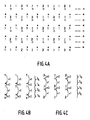
- Figs. 4A, 4B and 4C show how first and second fields, samples of which are indicated by an * and a 0, respectively, to be displayed on a high definition receiver, are obtained from first and second received fields, samples of which are indicated by a bold 1 and a bold 2, respectively.
- the inverse of the operation as shown in Fig. 2C is first carried out: in each received field, the samples located on one line are pushed apart, so that two lines with staggered samples are obtained.
- the situation indicated by the bold 1's in Figs. 4A and 4B then occurs for the first received field and the situation indicated by the bold 2's in Figs. 4A and 4B occurs for the second received field.
- the number of samples is subsequently doubled in each received field, so that thin 1's and 2's are obtained.
- Doubling the number of samples may be achieved mainly in two manners: doubling the number of samples will be achieved by means of spatial interpolation in the case of moving parts in the picture of the television signal, to avoid blurring, and doubling the number of samples will be achieved by means of filling-in the samples of the previous picture in the case of stationary parts in the picture of the television signal, to obtain a field suitable for a display with a high spatial resolution; with each first received field the samples of the previously received third field are used for that purpose and with each second received field the samples of the previously received fourth field are used therefor.
- the samples indicated by the 1's and 2's are at the same height, so that a correct interlace during display on the display arrangement of the high definition receiver is not yet obtained.
- the procedure described in the following is performed to place the lines of, on the one hand, the odd and on the other hand the even fields, precisely between eachother also during display on the display arrangement of the high definition receiver.
- the samples of the first field to be displayed indicated by an * are obtained each time by establishing a weighted average from a superjacent sample, indicated by a 1, which is given a weight 1, and a subjacent sample indicated by a 1, which is given a weight 3.
- the centres of gravity of the weighted average of the odd fields are located at 3/4 of the input lines located above the output lines and at 1/4 of the input lines located below the output lines, as is shown at the right hand side of the Figure.
- the samples of the second field to be displayed are obtained by establishing each time a weighted average from a superjacent sample, indicated by a 2, which is given the weight 3, and a subjacent sample indicated by a 2, which is given the weight 1.
- the centres of gravity of the weighted average of even fields are at 3/4 of the input lines lying below the output lines and at 1/4 of the input lines located above the output lines, as is shown at the right hand side of the Figure.
- Fig. 4A the lines of the odd and even fields are precisely placed between eachother, so that a correct interlace is achieved during display on the display arrangement 339 of the high definition receiver.
- first and second fields received are processed in the high definition receiver to form first and second fields to be displayed, having double the number of lines.
- Processing the third and fourth field received into a third and fourth field to be displayed is achieved in a similar manner.
- Each thin 1 or 2 as shown in Figs. 4A, 4B and 4C may be replaced by a bold 3 or 4, respectively, and each bold 1 or 2, as shown in Figs. 4A, 4B and 4C, may be replaced by a thin 3 or 4, respectively.
- the thin 3's and 4's may obtained in a similar manner by means of spatial interpolation and/or inserting samples of the first and second received fields, respectively, received in the preceding picture period.
- Third and fourth fields to be displayed samples of which are in exactly the same place as the samples of the first and second fields to be displayed, respectively, indicated by an and a 0, respectively, are obtained by weighted averaging, whereby the same weight factors must be used for the third fields to be displayed as for the first fields to be displayed and the same weight factors must be used for the fourth fields to be displayed as for the second fields to be displayed.
- the methods as described in the foregoing are the simplest methods of obtaining the desired position of the centres of gravity of the weighted averages. It will be obvious that other, more complex, weighted averaging operations are possible, it then also being possible to obtain a flatter frequency characteristic.
- the picture signals to be displayed on the high definition receiver which is preprocessed in the transmitter by the vertical (3, 1, 0) / (0, 3, 1) filtering (denoted also (3, 1) filtering in the sequel) or the vertical (1, 3, 0) / (0, 1, 3) filtering (denoted also (1, 3) filtering in the sequel), performed by the vertical filter circuit 39 of Fig.
- This dip may be avoided by convoluting the filtering operation in the transmitter by means of, for example, a (-1, 3 1/3, -1) correction filtration, which causes an amplification of signals having frequencies around half a sampling frequency, with which the picture signal is sampled, so that a vertical (-3, 9, 1/3, -1) filtration is ultimately applied in the transmitter, instead of the (3, 1) filtration.
- the convolution product of all filtering operations performed in the transmitter and in the receiver is then a vertical (-1, 0, 9 1/9, 0, -1) filtration, which has a much flatter frequency characteristic for its result.
- peaks occurring in the latter frequency characteristic at 1/4 and 3/4 of the sampling frequency may be further reduced by filtration with, for example a vertical (1, 0, 9 1/9, 0, 1) correction filtration.
- this correction filtration is also applied at the transmitter end a preprocessing with a vertical (-3, 9, -27, 81, 1/27, -1/9, 1/3, -1) filtration is ultimately performed.
- the convolution product of all filtering operations applied in the transmitter and in the receiver is in that case a vertical (-1, 0, 0, 0, 81, 1/81, 0, 0, 0, -1) filtration which results in a very flat frequency characteristic.
- the centre of gravity of the weighted averaging obtained by means of this last-mentioned filtration is still always in the same position as in the said first simple (3, 1) filtration, as the correction filtrations used are neutral as regards the centre of gravity.
- the correction filtering operation may also be carried out in the high definition receiver instead of in the transmitter.
- circuits which can be positioned in both the transmitter and the high definition receiver, in the transmitter, to enable a high definition receiver which is as simple and consequently as cheap as possible.
- an enhancing correction filter as the first-mentioned correction filter in the high definition receiver is disadvantageous, because the signal in the dip of the frequency characteristic has a relatively poor signal-to-noise ratio, but on the other hand placing this enhancing filter in the transmitter has the disadvantage that an interference pattern in the transmitted picture caused by interleaving samples originated from both sides of the transition becomes visible on a normal definition receiver to its full extent during a vertical transition in a picture of the picture signal.
- the latter consideration argues for placing the enhancing filter partly in the transmitter to obtain a sufficiently high signal-to-noise ratio on the one hand and to reduce the interference pattern to a certain degree on the other hand and the remaining part in the high definition receiver.
Landscapes
- Engineering & Computer Science (AREA)
- Multimedia (AREA)
- Signal Processing (AREA)
- Television Systems (AREA)
Applications Claiming Priority (2)
| Application Number | Priority Date | Filing Date | Title |
|---|---|---|---|
| NL8901399A NL8901399A (nl) | 1989-06-02 | 1989-06-02 | Werkwijze en inrichting voor het verminderen van het lijnental van een beeldsignaal, alsmede inrichting voor het vermeerderen van het lijnental van een beeldsignaal. |
| NL8901399 | 1989-06-02 |
Publications (1)
| Publication Number | Publication Date |
|---|---|
| EP0400752A1 true EP0400752A1 (fr) | 1990-12-05 |
Family
ID=19854765
Family Applications (1)
| Application Number | Title | Priority Date | Filing Date |
|---|---|---|---|
| EP90201366A Withdrawn EP0400752A1 (fr) | 1989-06-02 | 1990-05-29 | Procédé et dispositif pour diminuer le nombre de lignes d'un signal d'image ainsi que dispositif pour augmenter le nombre de lignes d'un signal d'image |
Country Status (3)
| Country | Link |
|---|---|
| EP (1) | EP0400752A1 (fr) |
| JP (1) | JPH0324883A (fr) |
| NL (1) | NL8901399A (fr) |
Cited By (1)
| Publication number | Priority date | Publication date | Assignee | Title |
|---|---|---|---|---|
| EP0817482A3 (fr) * | 1996-07-02 | 2000-04-26 | Matsushita Electric Industrial Co., Ltd. | Circuit de conversion de lignes de balayage et circuit pour la génération de coefficients d'interpolation |
Citations (6)
| Publication number | Priority date | Publication date | Assignee | Title |
|---|---|---|---|---|
| EP0114693A2 (fr) * | 1983-01-25 | 1984-08-01 | Robert Bosch Gmbh | Système de transmission d'un signal vidéo en couleur à haute définition |
| GB2139448A (en) * | 1983-03-02 | 1984-11-07 | British Broadcasting Corp | High Definition Video Signal Transmission |
| DE3341298A1 (de) * | 1983-11-15 | 1985-05-23 | Robert Bosch Gmbh, 7000 Stuttgart | System zur fernsehmaessigen uebertragung |
| EP0252563A2 (fr) * | 1986-07-08 | 1988-01-13 | Koninklijke Philips Electronics N.V. | Système de transmission et de réception d'un signal de télévision, ainsi que section de transmission et de réception pour un tel système |
| GB2194409A (en) * | 1986-01-14 | 1988-03-02 | British Broadcasting Corp | Compatible high definition video transmission systems |
| EP0288772A2 (fr) * | 1987-03-31 | 1988-11-02 | Pioneer Electronic Corporation | Procédé d'interpolation pour un système de transmission à sous-échantillonnage |
-
1989
- 1989-06-02 NL NL8901399A patent/NL8901399A/nl not_active Application Discontinuation
-
1990
- 1990-05-29 EP EP90201366A patent/EP0400752A1/fr not_active Withdrawn
- 1990-06-01 JP JP2141691A patent/JPH0324883A/ja active Pending
Patent Citations (6)
| Publication number | Priority date | Publication date | Assignee | Title |
|---|---|---|---|---|
| EP0114693A2 (fr) * | 1983-01-25 | 1984-08-01 | Robert Bosch Gmbh | Système de transmission d'un signal vidéo en couleur à haute définition |
| GB2139448A (en) * | 1983-03-02 | 1984-11-07 | British Broadcasting Corp | High Definition Video Signal Transmission |
| DE3341298A1 (de) * | 1983-11-15 | 1985-05-23 | Robert Bosch Gmbh, 7000 Stuttgart | System zur fernsehmaessigen uebertragung |
| GB2194409A (en) * | 1986-01-14 | 1988-03-02 | British Broadcasting Corp | Compatible high definition video transmission systems |
| EP0252563A2 (fr) * | 1986-07-08 | 1988-01-13 | Koninklijke Philips Electronics N.V. | Système de transmission et de réception d'un signal de télévision, ainsi que section de transmission et de réception pour un tel système |
| EP0288772A2 (fr) * | 1987-03-31 | 1988-11-02 | Pioneer Electronic Corporation | Procédé d'interpolation pour un système de transmission à sous-échantillonnage |
Non-Patent Citations (1)
| Title |
|---|
| SMPTE JOURNAL, vol. 92, no. 5, May 1983, pages 552-561, Scarsdale, New York, US; C.P. SANDBANK et al.: "High-definition television and compatibility with existing standards" * |
Cited By (2)
| Publication number | Priority date | Publication date | Assignee | Title |
|---|---|---|---|---|
| EP0817482A3 (fr) * | 1996-07-02 | 2000-04-26 | Matsushita Electric Industrial Co., Ltd. | Circuit de conversion de lignes de balayage et circuit pour la génération de coefficients d'interpolation |
| US6380979B1 (en) | 1996-07-02 | 2002-04-30 | Matsushita Electric Industrial Co., Ltd. | Scanning line converting circuit and interpolation coefficient generating circuit |
Also Published As
| Publication number | Publication date |
|---|---|
| JPH0324883A (ja) | 1991-02-01 |
| NL8901399A (nl) | 1990-06-01 |
Similar Documents
| Publication | Publication Date | Title |
|---|---|---|
| US4965667A (en) | Method and apparatus for processing signals conveyed in sub-sampled form by way of a transmission channel or record carrier | |
| KR890000981B1 (ko) | 텔레비젼 표시 시스템 | |
| US6281873B1 (en) | Video line rate vertical scaler | |
| US4603350A (en) | Interlaced digital video input filter/decimator and/or expander/interpolator filter | |
| EP0217628B1 (fr) | Filtre d'interpolation avec compensation de mouvement | |
| US4733300A (en) | Contour signal correction circuit for television receiver | |
| CA2225731A1 (fr) | Conversion de balayage multiformat | |
| EP0577165A1 (fr) | Appareil pour interpoler des signaux d'images par interpolation à compensation de mouvement | |
| US5089893A (en) | Picture element number converter | |
| JP2852743B2 (ja) | テレビジョン信号処理回路 | |
| CA1230669A (fr) | Systeme d'affichage a balayage progressif pour la television | |
| EP0277141A1 (fr) | Systemes de transmission video. | |
| BE1012172A5 (nl) | Werkwijze en inrichting voor videoverwerking. | |
| EP0948215B1 (fr) | Dispositif et méthode pour filtrer des signaux vidéo contenant de l'information de chrominance | |
| JPH0693596B2 (ja) | フィルタ及びそれを用いるデータ伝送システム | |
| KR100638255B1 (ko) | 샘플 속도 변환기와 데이터의 샘플 속도를 변환하는 방법 | |
| EP0400752A1 (fr) | Procédé et dispositif pour diminuer le nombre de lignes d'un signal d'image ainsi que dispositif pour augmenter le nombre de lignes d'un signal d'image | |
| WO1994015435A1 (fr) | Procedes et appareil destines a la multiplication de pixels d'images de television en temps reel | |
| EP0372774A3 (fr) | Méthode de conversion de la fréquence d'affichage d'un signal vidéo | |
| WO1999016239A2 (fr) | Elimination du moirage | |
| JPH04287487A (ja) | 順次走査変換装置 | |
| EP0496451B1 (fr) | Processeur de signal non-linéaire | |
| JPH04502988A (ja) | 高品位b―macテレビジョン信号送信システム | |
| GB2194409A (en) | Compatible high definition video transmission systems | |
| EP0382151A2 (fr) | Convertisseur abaisseur de fréquence d'échantillonnage et convertisseur élévateur de fréquence d'échantillonnage |
Legal Events
| Date | Code | Title | Description |
|---|---|---|---|
| PUAI | Public reference made under article 153(3) epc to a published international application that has entered the european phase |
Free format text: ORIGINAL CODE: 0009012 |
|
| AK | Designated contracting states |
Kind code of ref document: A1 Designated state(s): DE FR GB IT |
|
| 17P | Request for examination filed |
Effective date: 19910530 |
|
| STAA | Information on the status of an ep patent application or granted ep patent |
Free format text: STATUS: THE APPLICATION IS DEEMED TO BE WITHDRAWN |
|
| 18D | Application deemed to be withdrawn |
Effective date: 19921201 |