EP0400760A1 - Brancard - Google Patents
Brancard Download PDFInfo
- Publication number
- EP0400760A1 EP0400760A1 EP90201396A EP90201396A EP0400760A1 EP 0400760 A1 EP0400760 A1 EP 0400760A1 EP 90201396 A EP90201396 A EP 90201396A EP 90201396 A EP90201396 A EP 90201396A EP 0400760 A1 EP0400760 A1 EP 0400760A1
- Authority
- EP
- European Patent Office
- Prior art keywords
- handle
- bar
- stretcher
- bars
- cross
- Prior art date
- Legal status (The legal status is an assumption and is not a legal conclusion. Google has not performed a legal analysis and makes no representation as to the accuracy of the status listed.)
- Ceased
Links
- 230000007246 mechanism Effects 0.000 claims abstract description 9
- 230000000295 complement effect Effects 0.000 claims abstract description 4
- 238000005452 bending Methods 0.000 claims abstract description 3
- 230000033001 locomotion Effects 0.000 claims description 7
- 238000001125 extrusion Methods 0.000 claims 1
- 230000009471 action Effects 0.000 description 4
- 230000006378 damage Effects 0.000 description 2
- 230000035939 shock Effects 0.000 description 2
- XAGFODPZIPBFFR-UHFFFAOYSA-N aluminium Chemical compound [Al] XAGFODPZIPBFFR-UHFFFAOYSA-N 0.000 description 1
- 229910052782 aluminium Inorganic materials 0.000 description 1
- 239000004411 aluminium Substances 0.000 description 1
- 230000008901 benefit Effects 0.000 description 1
- 238000010276 construction Methods 0.000 description 1
- 239000000945 filler Substances 0.000 description 1
- 239000000463 material Substances 0.000 description 1
- 230000002093 peripheral effect Effects 0.000 description 1
- 230000007480 spreading Effects 0.000 description 1
Images


Classifications
-
- A—HUMAN NECESSITIES
- A61—MEDICAL OR VETERINARY SCIENCE; HYGIENE
- A61G—TRANSPORT, PERSONAL CONVEYANCES, OR ACCOMMODATION SPECIALLY ADAPTED FOR PATIENTS OR DISABLED PERSONS; OPERATING TABLES OR CHAIRS; CHAIRS FOR DENTISTRY; FUNERAL DEVICES
- A61G1/00—Stretchers
- A61G1/013—Stretchers foldable or collapsible
Definitions
- the invention relates to a stretcher consisting substantially of two parallel longitudinal bars, a cross connecting system holding these bars at a distance, a cover extending between these bars, a handle arranged in and outwardly slidable in each bar end of hollow form, wherein in each handle is arranged a locking mechanism.
- a stretcher must satisfy a number of conflicting requirements, among which may be included easy maneuverability, particularly where folding stretchers are concerned, together with a great stiffness and strength, wherein the weight of the stretcher must be as light as possible.
- the dimensions thereof must also be limited, to which end the stretcher is preferably provided with inwardly slidable handles in order to be able to reduce the length of the stretcher in storage or during use.
- the invention has for its object to provide a stretcher of the type described in the preamble which can satisfy these requirements and provides to this end a stretcher which is distinguished in that each bar is embodied as a hollow profile wherein a standing wall portion of the profile displays in cross section a substantially standing rectangular shape in order to enlarge the vertical bending stiffness of the bar.
- this standing rectangular wall portion is located on the outside of the stretcher in order to protect the stretcher against shocks.
- the rectangular cross sectional portion of the stretcher lends itself according to the invention in excellent manner to the arranging of at least one open channel wherein the bulb border of the carrying cover can be arranged.
- the carrying cover extends over the bar to the other parallel bar whereby the top side of the bars is cover ed.
- the cover can be arranged in a subdued colour, while the bar can nevertheless be embodied of random material and colour, for instance aluminium, which contributes to the lower weight.
- each bar preferably has a round form, for example circular or elliptical, wherewith sharp edges and possible injuries can thereby be avoided.
- the handle is preferably complementary with respect to outer periphery to the inner periphery of the bar, by arranging a flat surface on the handle the non-rotatability of this handle relative to the bar can be ensured.
- Such a non-rotatable guiding of the handle in the bar is of advantage if the handle is provided with a locking mechanism wherewith the handle can be locked in both the extended and pushed-in positions.
- the handle In order to increase user comfort it is recommended according to the invention to place the handle under spring loading, which spring is incorporated in the bar as a pressure spring which supports against a stop surface arranged therein.
- a manually operated embodiment is ensured by arranging an operating member in the handle itself for operating the locking device which, together with the spring loading, provides the very easy operation for the user by either just pressing in the operating member to bring out the handle or pressing in the handle counter to the pressure action of the spring.
- stop surface is arranged in the bar on a counter-member for the fixing means for a support for the stretcher as well as for the cross connecting system.
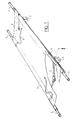
- the stretcher according to the invention consists of two parallel longitudinal bars 1, 2 which are held at a mutual distance by a cross connecting system 3. It is noted that the cross connecting system 3 here takes a pivoting form in order to be able to collapse the stretcher by carrying the longitudinal bars 1 and 2 towards each other. This is further elucidated below.
- the stretcher consists further of a cover 4 extending between the longitudinal bars 1 and 2, wherein at either end of each longitudinal bar 1 is arranged a handle 5. According to the invention this handle can be carried into the bar 1 so that the total length of the stretcher can be reduced.
- straps 6 are arranged in order to be able to fasten a body onto the stretcher.
- the bars are provided with supports 7 to hold the stretcher at some height above the bearing surface.
- each bar 1, 2 is embodied such that a standing wall portion 10 thereof is substantially rectangular in form, wherein the larger rectangular side stands vertical ly.
- the remaining part of the cross section takes a round form, for instance elliptical, wherein it is noted that the outer periphery of the handle 5 adapts close-fittingly into the inner space of the bar 1.
- the handle is therein provided with a flat surface 11 which can slide along the inward facing rectangular surface of the portion 10. Ensured therewith is the non-rotatability of the handle 5 relative to the bar 1.
- the rectangular wall portion 10 of the bar 1 displays two lengthwise channels 12 and 13 arranged one above the other, wherein the channel 12 is suitable for receiving the bulb border of the cover 4, see also fig. 7.
- the bulb border 14 of the cover is provided with a rod 15 such that this fits into the channel 12 which narrows towards the outside and therefore holds in the rod 15 with the bulb border 14 placed around it.
- the cover 4 can thus be stretched tightly.
- the second channel 13 serves to receive a bracket 16 to which are attached the fastening straps 6. These can slide to a random position along the length of the bar 1 and therefore be arranged at the optimal point with respect to the patient.
- the bracket 16 is such that the inner face thereof will not touch the bulb border 14 of the cover, which prevents damage thereto.
- the standing outer face 17 of the rectangular wall portion 10 for instance is slightly protruding relative to the flange of at least the channel part 12 so that this outer face 17 serves as protection against shocks and chafing of the bulb border 14 of the cover 4, see also fig. 7.
- the channels 12, 13 can be provided at either end with stoppers 18 whereby sliding out of the brackets 16 and the bulb border 14 of the cover is prevented.
- the handle 5 is arranged slidably relative to the bar 1, see fig. 3.
- the handle is embodied for this purpose with a locking mechanism 20 consisting of a pin 21 which can fall into an opening 22 on the underside of the bar and opening 23.
- the pin 21 is arranged slidably in vertical direction in the body of the handle 5 and stands under downward directed spring pressure of a spring 24.
- the spring supports against the inner wall portion of a blind hole in the handle 5. The movement of the pin 21 is such that it can be pulled entirely out of the hole 22, 23.
- an operating member 25 which extends in axial sense in the handle 5.
- the handle 5 is given a hollow form and can receive the operating member 25 which is rectangular in cross section and provided at one end with a sloping surface 26 that co-acts with a likewise sloping surface 27 of the pin 21.
- This sloping face 27 is formed by a recess in the pin the height whereof is at least as great as the height of the member 25.
- the member is provided with a push-button 28, the outer periphery of which fits precisely into a chamber 29 of the handle 5. Arranged in this chamber is a pressure spring 30.
- the member 25 is provided on the underside with a slot-like hole 31 for receiving a stop pin 32 arranged fixedly in the handle 5.
- Locking of the handle takes place as follows.
- the member 25 By pressing in the push-button 28, see fig. 5, the member 25 will move to the right in fig. 5 counter to the pressure action of the spring 30, whereby the sloping face 26 comes into contact with the face 27 of the pin 21. This will move upward against the action of the spring 24 and the bottom end of the pin is released from the hole 22.
- the inward movement of the member 25 is bounded by the pin 32.
- the handle 5 can be pushed into the bar 1, 2 until the pin 22 comes to lie above the hole 23 and, through release of the push-button 28 and carrying back of the member 25 as a consequence of the spring action 30, the pin 21 is released into the hole 23 whereby the handle 5 is locked in the bar 1.
- Unlocking of the hand-grip 5 can take place by again pressing in the button 28, wherein the hand-grip 5 can be pulled outward manually. Re-locking takes place by again guiding the pin 21 into the hole 22. Because of the non-rota tability of the handle 5 this movement takes place without disturbance.
- a bounding element 40 which hooks with an eye-shaped end 41 around a cross pin 42 which is fixed in the body of the handle 5.
- the other end of the bounding element 40 is provided with a slot-like opening in the end portion which co-acts with a cross pin 43 attached fixedly in the bar 1, 2.
- the length of the slot-like opening which is formed by an end of the rod-shaped bounding element 40 being bent round in hairpin shape is at least equal to the stroke length of the handle 5.
- the above mentioned counter-screw member 38 serves as counter-member for fixing of the support 7.
- the support 7 is substantially trapezium-shaped and is a sawn-off product of an extruded profile.
- a slot-like opening 45 Arranged on the end of the support 7 situated by the bar 1, 2 is a slot-like opening 45 which serves to receive the end of the cross connecting arms 3.
- the pin 43 is provided with a screw thread which co-acts with a threaded hole in the screw body 38. This pin 43 extends through the support 7 and ends in a screw head or bolt 46.
- the pin 43 also serves as spindle for the pivoting of arm 3 relative to the bars 2, which is further elucidated below.
- the counter-screw member 38 has a peripheral shape complementary to the inside wall of the bar 1, 2, see also fig. 7, and is therefore non-rotatably slidable in the bar as a result of the flat inner surface of the rectangular portion 10.
- the screw member 38 is provided with a chamber 47 into which fits a pin 48 that is outwardly loaded by a pressure spring 49.
- the pin 48 falls into a series of aligned holes in the bottom wall of the bar 1, 2, a filler element 50 arranged between the bar and the support and the support 7. Ensured with this construction together with the pin 43 is that the support 7 can be attached non-rotatably to the bar 1, 2.
- Fitting takes place in particularly simple manner due to the resilient pin 48 which, by sliding the body 38 in the bar 1, falls automatically into the aligned holes and positions the different parts on each other. After arranging the bounding element 40 and the pin 42 the whole spring-tensioned handle with locking mechanism can be pushed simultaneously into the bars 1 and fixed in place with pin 43.
- the cross connecting system is constructed from two mutually pivoting arms 3.
- the ends of each arm 3 facing one another are coupled to a connecting piece 50 which is arranged such that it functions as stop over the extended idle point of the arms 3.
- the pivot point of the arms lies at the pin 51 and is dimensioned relative to the stop part 50 such that the arms 3 are pressed through the position straight opposite one another, whereby together with the tension in the cover 4 the desired locking is effected, which is indicated by the arrow P1 in fig. 7.
- the operation of the stretcher can therefore be performed without additional tools, since the user only needs to fold out the arms 3 of the cross connecting system, whereby the bars 1, 2 move away from one another.
Landscapes
- Health & Medical Sciences (AREA)
- Life Sciences & Earth Sciences (AREA)
- Animal Behavior & Ethology (AREA)
- General Health & Medical Sciences (AREA)
- Public Health (AREA)
- Veterinary Medicine (AREA)
- Handcart (AREA)
- Purses, Travelling Bags, Baskets, Or Suitcases (AREA)
Applications Claiming Priority (2)
| Application Number | Priority Date | Filing Date | Title |
|---|---|---|---|
| NL8901396A NL8901396A (nl) | 1989-06-01 | 1989-06-01 | Draagbaar. |
| NL8901396 | 1989-06-01 |
Publications (1)
| Publication Number | Publication Date |
|---|---|
| EP0400760A1 true EP0400760A1 (fr) | 1990-12-05 |
Family
ID=19854763
Family Applications (1)
| Application Number | Title | Priority Date | Filing Date |
|---|---|---|---|
| EP90201396A Ceased EP0400760A1 (fr) | 1989-06-01 | 1990-05-31 | Brancard |
Country Status (2)
| Country | Link |
|---|---|
| EP (1) | EP0400760A1 (fr) |
| NL (1) | NL8901396A (fr) |
Cited By (7)
| Publication number | Priority date | Publication date | Assignee | Title |
|---|---|---|---|---|
| WO1995020933A1 (fr) * | 1994-02-04 | 1995-08-10 | Reilly Royalties Limited | Civiere pliante ou extensible |
| FR2722401A1 (fr) * | 1994-07-13 | 1996-01-19 | Daouk Antar | Civiere pliante parachutable |
| EP0868163A4 (fr) * | 1995-11-07 | 2001-04-18 | Ferno Washington | Commande de poignee extensible pour chassis de roulement de civiere |
| US8122673B2 (en) * | 2007-10-27 | 2012-02-28 | Ellis J Nigel | Portable safety skylight replacement assembly |
| WO2017212001A1 (fr) * | 2016-06-08 | 2017-12-14 | Plass Medtech Ag | Brancard multifonctionnel |
| CN108542611A (zh) * | 2018-05-11 | 2018-09-18 | 南京理工大学 | 一种担架与急救床结合的多功能救援设备 |
| CN117136041A (zh) * | 2021-01-19 | 2023-11-28 | 安塔尔·达乌克 | 改进的可折叠担架 |
Citations (8)
| Publication number | Priority date | Publication date | Assignee | Title |
|---|---|---|---|---|
| NL289722A (fr) * | 1900-01-01 | |||
| US2305980A (en) * | 1941-07-24 | 1942-12-22 | Zimmer Thomson Corp | Leg for litters |
| CH239806A (fr) * | 1942-10-15 | 1945-11-15 | Mani Louis | Dispositif comprenant au moins un ensemble extensible présentant deux éléments tubulaires coulissants. |
| GB820713A (en) * | 1956-09-24 | 1959-09-23 | Stollenwerk Hans | Improvements in or relating to stretchers |
| FR1494826A (fr) * | 1966-06-30 | 1967-09-15 | Rousseau Et Cie | Poignée rentrante pour brancards et civières |
| NL6907750A (fr) * | 1968-06-04 | 1969-12-08 | ||
| DE3245842A1 (de) * | 1982-12-10 | 1984-06-14 | Utila Gerätebau GmbH & Co KG, 5000 Köln | Krankentransportgeraet, insbesondere krankentrage |
| DE3524279A1 (de) * | 1985-07-06 | 1987-01-15 | Stollenwerk Fabrik Fuer Sanita | Krankentrage |
-
1989
- 1989-06-01 NL NL8901396A patent/NL8901396A/nl not_active Application Discontinuation
-
1990
- 1990-05-31 EP EP90201396A patent/EP0400760A1/fr not_active Ceased
Patent Citations (8)
| Publication number | Priority date | Publication date | Assignee | Title |
|---|---|---|---|---|
| NL289722A (fr) * | 1900-01-01 | |||
| US2305980A (en) * | 1941-07-24 | 1942-12-22 | Zimmer Thomson Corp | Leg for litters |
| CH239806A (fr) * | 1942-10-15 | 1945-11-15 | Mani Louis | Dispositif comprenant au moins un ensemble extensible présentant deux éléments tubulaires coulissants. |
| GB820713A (en) * | 1956-09-24 | 1959-09-23 | Stollenwerk Hans | Improvements in or relating to stretchers |
| FR1494826A (fr) * | 1966-06-30 | 1967-09-15 | Rousseau Et Cie | Poignée rentrante pour brancards et civières |
| NL6907750A (fr) * | 1968-06-04 | 1969-12-08 | ||
| DE3245842A1 (de) * | 1982-12-10 | 1984-06-14 | Utila Gerätebau GmbH & Co KG, 5000 Köln | Krankentransportgeraet, insbesondere krankentrage |
| DE3524279A1 (de) * | 1985-07-06 | 1987-01-15 | Stollenwerk Fabrik Fuer Sanita | Krankentrage |
Cited By (9)
| Publication number | Priority date | Publication date | Assignee | Title |
|---|---|---|---|---|
| WO1995020933A1 (fr) * | 1994-02-04 | 1995-08-10 | Reilly Royalties Limited | Civiere pliante ou extensible |
| FR2722401A1 (fr) * | 1994-07-13 | 1996-01-19 | Daouk Antar | Civiere pliante parachutable |
| EP0868163A4 (fr) * | 1995-11-07 | 2001-04-18 | Ferno Washington | Commande de poignee extensible pour chassis de roulement de civiere |
| US8122673B2 (en) * | 2007-10-27 | 2012-02-28 | Ellis J Nigel | Portable safety skylight replacement assembly |
| WO2017212001A1 (fr) * | 2016-06-08 | 2017-12-14 | Plass Medtech Ag | Brancard multifonctionnel |
| US11517486B2 (en) | 2016-06-08 | 2022-12-06 | Plass Rescue Technologies Ag | Multi-functional stretcher |
| CN108542611A (zh) * | 2018-05-11 | 2018-09-18 | 南京理工大学 | 一种担架与急救床结合的多功能救援设备 |
| CN108542611B (zh) * | 2018-05-11 | 2024-01-30 | 南京理工大学 | 一种担架与急救床结合的多功能救援设备 |
| CN117136041A (zh) * | 2021-01-19 | 2023-11-28 | 安塔尔·达乌克 | 改进的可折叠担架 |
Also Published As
| Publication number | Publication date |
|---|---|
| NL8901396A (nl) | 1991-01-02 |
Similar Documents
| Publication | Publication Date | Title |
|---|---|---|
| US5769293A (en) | Automobile trunk organizer | |
| US4988026A (en) | Discretely adjustable support rail for luggage carriers | |
| US4285486A (en) | Cord holder | |
| US20010010431A1 (en) | Attachment for child seat | |
| US5524957A (en) | Chair accessory | |
| EP0400760A1 (fr) | Brancard | |
| EP0404745A1 (fr) | Barre téléscopique de chargement | |
| US5813368A (en) | Hand-held dog restraint | |
| JP7401653B2 (ja) | 折畳み式高さ調節可能テーブル | |
| US20020062524A1 (en) | Mattress and sheet attachment assembly | |
| EP1306266B1 (fr) | Barre de chargement | |
| US5730264A (en) | Luggage structure for transporting a plurality of cases | |
| GB2225716A (en) | Collapsible non-slipping bed guard | |
| EP1069031B1 (fr) | Agencement de couchette dans une cabine de camion | |
| US6957840B1 (en) | Tailgate extension system | |
| US6094784A (en) | Apparatus and system for securing cargo | |
| US5938260A (en) | Hand carrier for shrunk wrap coils of filamentary material | |
| EP4140356B1 (fr) | Support de sèche-cheveux | |
| US4880079A (en) | Ladder cap | |
| US3560038A (en) | Lever actuated fastener assembly | |
| US5595128A (en) | Table assembly | |
| US5398385A (en) | Cargo transport accessory | |
| WO1995020933A1 (fr) | Civiere pliante ou extensible | |
| EP1226049A1 (fr) | Perfectionnement portant sur des ancrages de sangles | |
| US5996177A (en) | Handle assembly for a collapsible luggage trolley |
Legal Events
| Date | Code | Title | Description |
|---|---|---|---|
| PUAI | Public reference made under article 153(3) epc to a published international application that has entered the european phase |
Free format text: ORIGINAL CODE: 0009012 |
|
| AK | Designated contracting states |
Kind code of ref document: A1 Designated state(s): BE DE FR GB IT NL |
|
| 17P | Request for examination filed |
Effective date: 19910426 |
|
| 17Q | First examination report despatched |
Effective date: 19920814 |
|
| STAA | Information on the status of an ep patent application or granted ep patent |
Free format text: STATUS: THE APPLICATION HAS BEEN REFUSED |
|
| 18R | Application refused |
Effective date: 19930728 |