EP0400767A2 - Schneidzahnanordnung - Google Patents
Schneidzahnanordnung Download PDFInfo
- Publication number
- EP0400767A2 EP0400767A2 EP90300051A EP90300051A EP0400767A2 EP 0400767 A2 EP0400767 A2 EP 0400767A2 EP 90300051 A EP90300051 A EP 90300051A EP 90300051 A EP90300051 A EP 90300051A EP 0400767 A2 EP0400767 A2 EP 0400767A2
- Authority
- EP
- European Patent Office
- Prior art keywords
- cutting point
- cutting
- holding clamp
- axially
- snout
- Prior art date
- Legal status (The legal status is an assumption and is not a legal conclusion. Google has not performed a legal analysis and makes no representation as to the accuracy of the status listed.)
- Withdrawn
Links
Images



Classifications
-
- E—FIXED CONSTRUCTIONS
- E02—HYDRAULIC ENGINEERING; FOUNDATIONS; SOIL SHIFTING
- E02F—DREDGING; SOIL-SHIFTING
- E02F9/00—Component parts of dredgers or soil-shifting machines, not restricted to one of the kinds covered by groups E02F3/00 - E02F7/00
- E02F9/28—Small metalwork for digging elements, e.g. teeth scraper bits
-
- E—FIXED CONSTRUCTIONS
- E02—HYDRAULIC ENGINEERING; FOUNDATIONS; SOIL SHIFTING
- E02F—DREDGING; SOIL-SHIFTING
- E02F9/00—Component parts of dredgers or soil-shifting machines, not restricted to one of the kinds covered by groups E02F3/00 - E02F7/00
- E02F9/28—Small metalwork for digging elements, e.g. teeth scraper bits
- E02F9/2808—Teeth
- E02F9/2816—Mountings therefor
- E02F9/2825—Mountings therefor using adapters
Definitions
- This invention relates to a cutting tooth assembly for use in ground cutting machines, such as earth moving machines, agricultural machines, or mining machines, and such machines as used in the construction industry. Typical of such machines are scarifiers, rippers, back-diggers, power shovels and rotary cutting machines.
- the cutting points themselves must of necessity be formed from an extremely hard material that is resistant to wear, and also one which is highly resistant to fatigue fracture in order to provide for an extended life of the points when in use.
- One form of shank as disclosed in Smith et al. US 3,750,761 includes a holder into which the cutting point is inserted and then secured in position by means of bolts.
- Such an arrangement suffers from the disadvantages that the bolts work loose under the severe impacts and vibrations encountered by the tool when in use. Additionally, the heads of the bolts become worn down making them difficult or impossible to remove by a wrench.
- shank disclosed in Gustafson, U.S. 2,222,071
- the cutting point has a socket of corresponding form, and had side flanges that extend into the grooves of the holder, the side flanges being correspondingly inclined for them to be received within the grooves. In this manner, axial forces which are exerted on the cutting point when in use act to drive the cutting point further into clamping engagement by wedging it further into its associated holder.
- the holding portion is formed in substantially the same shape as in the prior construction, but, entirely separately from the cutting point.
- the holding portion is thus in the form of a clamp which is employed for holding the cutting point by wedged onto the supporting shank.
- the cutting point is then formed separately with a shank portion of its own formed integrally with the cutting tip, the shank portion being received within the holding clamp and clamped directly onto the shank by the holding clamp.
- This construction material ly reduces the amount of material that must be discarded on breakage or wearing down of the cutting point, to the cutting point of the tooth and its associated integral shank portion.
- the holding clamp is not discarded, but instead is available for holding a replacement cutting point, the holding clamp itself being far less subject to wear by abrasion than is the cutting point itself, and thus lasting for several uses.
- Smith et al. U.S. 3750761 teaches a cutting point that can be formed other than by drop forging or casting. Smith teaches the formation of the cutting point of the tooth from a continuous length of bar stock, which can be produced by rolling or drawing, or extrusion. However, Smith's teachings are of attachment of his cutting point to the main shank using the old technology of employing securing bolts, and which is encumbered with all of the disadvantages of the known technology.
- the problem addressed herein is to provide a new type of cutting tooth assembly which preferably avoids most or all of tbe above-mentioned drawbacks while retaining the various good features already known.
- the cutting tooth assembly includes a main shank, and a channel-type holding clamp secured to the main shank by a frictional wedging grip.
- the holding clamp is formed to accept and secure a cutting point of a cutting tooth formed from continuous steel bar of constant transverse cross-section.
- the holding clamp and the main shank are formed so as to maintain the frictional wedging grip of the holding clamp in the presence of axial forces exerted on the cutting point.
- Axial forces present while the cutting tooth is in service act in the same direction as those required for fastening the tooth assembly. Those forces actually may drive the cutting point along with the holding clamp further into clamping wedging engagement with the holding shank, effectively preventing any loosening of the cutting tooth assembly.
- stops are attached to the bar stock, the stops being positioned for them to engage the end of the holding clamp and force the holding clamp further into frictional wedging grip with the main shank during use of the cutting tooth.
- stops can be provided in the holder. These stops provide an abutment for the cutting point preventing the cutting point from moving further backwards when subjected to axial forces, those forces acting to drive the cutting point along with the holding clamp further into clamping wedging engagement with he holding shank, thus effectively preventing any loosening of the cutting tooth assembly.
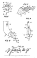
- a cutting tooth assembly embodying the invention comprises a shank 20 of conventional form formed of very hard steel, which is to be attached to a machine by dowels or by any other convenient manner,eg. as conventional in the art.
- the shank 20 has a snout 21 which provides an upwardly inclined planar upper surface 22 destined to receive the cutting point, and has a bottom surface 23 which also is inclined upwardly towards the free end of the shank, such that the bottom of the edge 23 lies within the radius of movement of a cutting point 30.
- the snout 21 is provided on its opposite sides with axially straight grooves 24, which diverge from the planar face 22 from the open end of the grooves, at a small angle of, for example, 4° or less.
- Planar surface 22 and grooves 24 are smooth surfaces providing for relatively low friction coefficient.
- the cutting point 30 has a forward cutting edge 31, and is in the form of a standard flat bar of steel. preferably the steel has a hardness of 50 Rockwell C. and a resistance to bending of 220 kPSI so that it can stand up to the hard use to which it is to be subjected, and for it to resist wear and fatigue under the extremely high stresses imposed on the cutting point during use.
- the holding clamp 32 is of U-shaped configuration, and preferably is made of forged steel having an approximate hardness of 47-48 Rockwell C., thus providing the holding clamp 32 with greater ductility than that of the cutting point 30.
- the holding clamp 32 has a front end 33 and a rear end 34, and tapers from its rear end 34 to its forward end 33, such that keys 35 at the open side of the U-shaped configuration diverge from the forward end 33 to the rearward end 34 of the holding clamp at the same angle as the divergence of the grooves 24 in the snout 21.
- the holding clamp 32 includes axial surfaces 36 and 37 adapted to embrace the sides of the snout 21 to prevent the holding clamp from angling relative to the snout 21, and also includes planar surfaces 38, 39 and 40 adapted to receive and embrace the cutting point 30, fitting its upper and side surfaces.
- Surface 39 of the holding clamp is smoother than surface 40 in order to provide for a lower friction coefficient for the surface 39 than for the surface 40.
- the cutting point 30 is inserted into the holding clamp 32, and the holding clamp 32 is then positioned over the snout 21 of the shank 20, with its side flanges 35 positioned within the side grooves 24 of the snout.
- the cutting point 30 and the holding clamp 32 are then moved onto the snout 21, the flanges 35 of the holding clamp at this time progressively moving along the inclined grooves 24, to move the holding clamp 32 downwardly into clamping engagement with the cutting point 30 and in turn, to move the cutting point 30 into clamping engagement with the upper planar surface 22 of the snout.
- a locking tool 50 can be positioned over the end of the cutting point 30, and the holding clamp 32 can be given a sharp tap on its forward end 33 using a mallet 51 in order to secure the holding clamp 32 and the cutting point 30 securely on the snout 21.
- any impacts by stones and the like on the front end of the holding clamp 32 also act to move the holding clamp into closer frictional engagement with the cutting point 30 and the snout 21.
- the cutting point 30 is of constant transverse cross-section throughout its length.
- the receiving channel in the holding clamp 32 also is of constant transverse cross-section throughout its length.
- the cutting point 30 Once the cutting point 30 has worn down to an extent requiring its extension, it can be extended merely by loosening the holding clamp 32, sliding the cutting point 30 forwardly and then re-tightening the holding clamp 32.
- the rear end of the holding clamp 32 is provided with abutments 41 which extend into the channel provided for the reception of the cutting point 30.
- abutments 41 which extend into the channel provided for the reception of the cutting point 30.
- axial forces exerted on the cutting end 31 of the cutting point 30 will be transmitted directly to the stops 41 of the holding clamp 32, and will act to force the components of the entire assembly into closer frictional engagement with each other.
- side stops 42 can be attached to the lateral edges of the cutting point 30 for them to abut the holding clamp 32 at its forward end. At the time the cutting point 30 is extended for further use, then, further stops 42 can be welded to its side edges. The stops 42 when reaching the position of cutting edge 31 ultimately are consumed by abrasion of the cutting edge 31. Thus, they do not interfere with the welding of the end of an unused cutting point 30 to the unused end of a used cutting point.
- FIGs 11-13 an alternative construction of the embodiment as shown in Figures 1-5 is illustrated.
- the same reference numerals have been used as those used in Figures 1-5 to denote members in common with Figures 1-5.
- the cutting tooth assembly includes a shank 20 having a snout 21 with an upwardly extending lower edge 23.
- the shank 20 is split into two sections 20A and 20B in a plane that includes the plane of the upper planar surface 22 of the snout 21.
- the respective shank portions 20A and 20B are interconnected with each other by side plates 53-53 which are welded to the respective shank portions 20A and 20B, and which maintain the respective shank portions 20A and 20B held immovably in spaced relation at their adjacent end faces for them to define a slot 20C extending through the shank, through which a cutting point 30 of any axial length can extend in parallel face to face relation with the upper surface 22 of the snout 21.
- FIG. 14-16 in which again the same reference numerals are employed as those employed in the description of Figures 1-5, a modified form of cutting tooth assembly is shown which is specifically adapted to an earth levelling or planing machine.
- the shanks 20 are axially straight, such that they comprise, essentially, the snout portion only of the shank 20 of Figures 1-12.
- the shanks 20 each are welded or otherwise secured to a base plate 54 with the snouts 21 of the respective shanks 20 extending forwardly of a leading edge of the base plate 54.
- the shanks 20 support cutting points 30 which are secured to the snouts 21 by holding clamps 32, exactly in the manner previously described.
- Figures 14-16 is an inversion of the configuration of Figures 1-13, in that the cutting points are secured to a lower face of the associated snouts, the respective axially straight grooves 24 diverging upwardly from the lower surfaces of the snouts from the free ends of the snouts.
- a holding clamp 32 is positioned over the front of the snout, a cutting point 30 is inserted into the holding clamp, and then, the holding clamp is driven onto the snout 21 to immovably clamp the cutting point 30 onto the snout.
- the spaces between the respective cutting points 31 can accommodate planing teeth 56, which can be attached directly to the base plate 54 by bolts 58.
- planing teeth 56 are subject to less wear than the cutting points 30, in view of which they require to be replaced less frequently that is the case with the cutting points 30.
Landscapes
- Engineering & Computer Science (AREA)
- Mining & Mineral Resources (AREA)
- Civil Engineering (AREA)
- General Engineering & Computer Science (AREA)
- Structural Engineering (AREA)
- Milling Processes (AREA)
- Percussive Tools And Related Accessories (AREA)
- Road Repair (AREA)
Applications Claiming Priority (2)
| Application Number | Priority Date | Filing Date | Title |
|---|---|---|---|
| US07/359,515 US4899830A (en) | 1987-05-21 | 1989-06-01 | Cutting tooth assembly for heavy duty earth working machines |
| US359515 | 1994-12-20 |
Publications (2)
| Publication Number | Publication Date |
|---|---|
| EP0400767A2 true EP0400767A2 (de) | 1990-12-05 |
| EP0400767A3 EP0400767A3 (de) | 1991-09-11 |
Family
ID=23414152
Family Applications (1)
| Application Number | Title | Priority Date | Filing Date |
|---|---|---|---|
| EP19900300051 Withdrawn EP0400767A3 (de) | 1989-06-01 | 1990-01-03 | Schneidzahnanordnung |
Country Status (4)
| Country | Link |
|---|---|
| US (1) | US4899830A (de) |
| EP (1) | EP0400767A3 (de) |
| KR (1) | KR970011615B1 (de) |
| CA (1) | CA2005449A1 (de) |
Cited By (1)
| Publication number | Priority date | Publication date | Assignee | Title |
|---|---|---|---|---|
| KR100862793B1 (ko) * | 2002-04-26 | 2008-10-13 | 주식회사 포스코 | 크레인 폴립의 에지 공급장치 |
Families Citing this family (10)
| Publication number | Priority date | Publication date | Assignee | Title |
|---|---|---|---|---|
| FR2669658B1 (fr) * | 1990-11-26 | 1993-02-12 | Plaisance Jean Marie | Rateau de debroussaillage, notamment pour engins de travaux publics. |
| US5148616A (en) * | 1990-12-21 | 1992-09-22 | A.M. Logistics Corporation | Adaptor for earth working cutting teeth and holding clamp |
| US5653048A (en) * | 1995-11-06 | 1997-08-05 | Esco Corporation | Wear assembly for a digging edge of an excavator |
| DE10350540A1 (de) * | 2003-10-29 | 2005-06-09 | Liebherr-Hydraulikbagger Gmbh | Grab- bzw.Greifwerkzeug |
| US20050229442A1 (en) * | 2004-03-30 | 2005-10-20 | Esco Corporation | Wear edge assembly |
| US7596895B2 (en) * | 2004-03-30 | 2009-10-06 | Esco Corporation | Wear assembly |
| US8205362B2 (en) * | 2009-05-12 | 2012-06-26 | Yeomans Allan J | Digging point assembly |
| US9404240B2 (en) | 2013-11-07 | 2016-08-02 | Caterpillar Inc. | Bucket lip protection assemblies and lip adapters for same |
| CN106416463B (zh) * | 2016-10-17 | 2018-12-18 | 东北农业大学 | 一种滚压轮配气式气压深松机 |
| US20220267986A1 (en) * | 2021-02-24 | 2022-08-25 | Theodore H. CORRIHER | Ripper shank, shank holder, and ground engaging implement for using the same |
Family Cites Families (11)
| Publication number | Priority date | Publication date | Assignee | Title |
|---|---|---|---|---|
| US183907A (en) * | 1876-10-31 | Improvement in plow-points | ||
| US3084A (en) * | 1843-05-12 | Eters | ||
| US819390A (en) * | 1904-06-16 | 1906-05-01 | Thomas J Warren | Plow. |
| US2082283A (en) * | 1936-03-10 | 1937-06-01 | Joseph R Godfrey | Scarifier tooth |
| US2148925A (en) * | 1936-11-25 | 1939-02-28 | Bochy Richard | Method of repointing a worn excavator tooth |
| US2222071A (en) * | 1938-12-13 | 1940-11-19 | Caterpillar Tractor Co | Detachable scarifier tooth |
| FR933481A (fr) * | 1946-08-31 | 1948-04-22 | Perfectionnements aux pièces et outils agricoles destinés à attaquer directement le sol | |
| US2940192A (en) * | 1957-09-12 | 1960-06-14 | Cleveland Trencher Co | Tooth for excavators |
| US3550691A (en) * | 1967-11-29 | 1970-12-29 | Caterpillar Tractor Co | Adjustable ripper tip |
| US3750761A (en) * | 1971-09-27 | 1973-08-07 | Caterpillar Tractor Co | Ripper with top-mounted extendible tip |
| US4576239A (en) * | 1984-08-27 | 1986-03-18 | Launder Richard L | Scarifier tooth assembly |
-
1989
- 1989-06-01 US US07/359,515 patent/US4899830A/en not_active Expired - Fee Related
- 1989-12-13 CA CA002005449A patent/CA2005449A1/en not_active Abandoned
- 1989-12-22 KR KR1019890019275A patent/KR970011615B1/ko not_active Expired - Lifetime
-
1990
- 1990-01-03 EP EP19900300051 patent/EP0400767A3/de not_active Withdrawn
Cited By (1)
| Publication number | Priority date | Publication date | Assignee | Title |
|---|---|---|---|---|
| KR100862793B1 (ko) * | 2002-04-26 | 2008-10-13 | 주식회사 포스코 | 크레인 폴립의 에지 공급장치 |
Also Published As
| Publication number | Publication date |
|---|---|
| KR970011615B1 (ko) | 1997-07-12 |
| EP0400767A3 (de) | 1991-09-11 |
| KR910001187A (ko) | 1991-01-30 |
| US4899830A (en) | 1990-02-13 |
| CA2005449A1 (en) | 1990-12-01 |
Similar Documents
| Publication | Publication Date | Title |
|---|---|---|
| US6382277B1 (en) | Stump grinding wheel and cutting assemblies therefor | |
| AU2008202834C1 (en) | Wear assembly for the digging edge of an excavator | |
| US4899830A (en) | Cutting tooth assembly for heavy duty earth working machines | |
| US8522843B2 (en) | Indexable stump cutter tooth | |
| US5370448A (en) | Wedging arrangement for attaching a bit holder to the base member of a mining road working, or earth moving machine | |
| US4625810A (en) | Tillage tool | |
| EP1259105B1 (de) | Arbeitsgerät mit auswechselbarer spitze | |
| EP0414751A1 (de) | Mit karbidverschleissplatte versehener baggerzahnanordnung. | |
| AU2002253760A1 (en) | Stump grinding wheel and cutting assemblies therefor | |
| US5027535A (en) | Boltless holding clamp for earth working cutting teeth | |
| US7520570B2 (en) | Tool extraction system for rotary cutter device | |
| AU2001231991A1 (en) | Working tool with replaceable working bit | |
| US4576239A (en) | Scarifier tooth assembly | |
| US5148616A (en) | Adaptor for earth working cutting teeth and holding clamp | |
| AU672964B2 (en) | Attachment assembly for excavation teeth | |
| CA2478443C (en) | Releasable auger tooth with shock-absorbing retaining means | |
| JPH05311703A (ja) | 保持用クランプ及び切削刃組立体 | |
| CA2182295A1 (en) | Chain saw file angle guide | |
| AU2002301249B2 (en) | Excavator teeth | |
| AU2013205220A1 (en) | Wear assembly for the digging edge of an excavator | |
| WO1995021715A1 (en) | Chain saw file angle guide |
Legal Events
| Date | Code | Title | Description |
|---|---|---|---|
| PUAI | Public reference made under article 153(3) epc to a published international application that has entered the european phase |
Free format text: ORIGINAL CODE: 0009012 |
|
| AK | Designated contracting states |
Kind code of ref document: A2 Designated state(s): AT BE CH DE DK ES FR GB GR IT LI LU NL SE |
|
| PUAL | Search report despatched |
Free format text: ORIGINAL CODE: 0009013 |
|
| RHK1 | Main classification (correction) |
Ipc: E02F 5/32 |
|
| AK | Designated contracting states |
Kind code of ref document: A3 Designated state(s): AT BE CH DE DK ES FR GB GR IT LI LU NL SE |
|
| 17P | Request for examination filed |
Effective date: 19920110 |
|
| 17Q | First examination report despatched |
Effective date: 19930818 |
|
| STAA | Information on the status of an ep patent application or granted ep patent |
Free format text: STATUS: THE APPLICATION IS DEEMED TO BE WITHDRAWN |
|
| 18D | Application deemed to be withdrawn |
Effective date: 19950815 |