EP0400899A2 - Gerät zur Wiedergabe von aufgezeichneten Daten - Google Patents
Gerät zur Wiedergabe von aufgezeichneten Daten Download PDFInfo
- Publication number
- EP0400899A2 EP0400899A2 EP90305672A EP90305672A EP0400899A2 EP 0400899 A2 EP0400899 A2 EP 0400899A2 EP 90305672 A EP90305672 A EP 90305672A EP 90305672 A EP90305672 A EP 90305672A EP 0400899 A2 EP0400899 A2 EP 0400899A2
- Authority
- EP
- European Patent Office
- Prior art keywords
- signal
- track
- recorded
- traced
- read
- Prior art date
- Legal status (The legal status is an assumption and is not a legal conclusion. Google has not performed a legal analysis and makes no representation as to the accuracy of the status listed.)
- Granted
Links
Images


Classifications
-
- G—PHYSICS
- G11—INFORMATION STORAGE
- G11B—INFORMATION STORAGE BASED ON RELATIVE MOVEMENT BETWEEN RECORD CARRIER AND TRANSDUCER
- G11B20/00—Signal processing not specific to the method of recording or reproducing; Circuits therefor
- G11B20/22—Signal processing not specific to the method of recording or reproducing; Circuits therefor for reducing distortions
-
- G—PHYSICS
- G11—INFORMATION STORAGE
- G11B—INFORMATION STORAGE BASED ON RELATIVE MOVEMENT BETWEEN RECORD CARRIER AND TRANSDUCER
- G11B7/00—Recording or reproducing by optical means, e.g. recording using a thermal beam of optical radiation by modifying optical properties or the physical structure, reproducing using an optical beam at lower power by sensing optical properties; Record carriers therefor
- G11B7/004—Recording, reproducing or erasing methods; Read, write or erase circuits therefor
- G11B7/005—Reproducing
Definitions
- the present invention relates to an apparatus for reading recorded information from a recording medium (for example, an optical disk) having a track for recording information.
- a recording medium for example, an optical disk
- Optical disks such as laser vision disks have so-called track structures.
- signals are recorded by forming a train of signal pits spirally from inner circumference to outer circumference of the optical disk.
- optical disks having the track structures encounter the problem of crosstalk in which the signal read from a track which is being traced contains the signals recorded on adjacent tracks. It is pointed out that the crosstalk is caused by the fact that a reading laser beam illuminates not only the track to be traced but also the adjacent tracks due to the relation between the spot diameter of the laser beam and the interval between adjacent tracks. As a result, the signals recorded on the tracks adjacent to the traced track are also read together with the signal recorded on the desired track.
- the first method includes the steps of detecting the inclination of an optical pickup and correcting the position of the optical pickup so that it always correctly opposes the recording surface of an optical disk.
- the second method includes the steps of simultaneously read three adjacent tracks and performing subtraction using them.
- the first method utilizes an arrangement in which a light emitted from a light emitting element and reflected by the optical disk, is received by two light receiving elements disposed adjacent to the light emitting element on opposite sides thereof.
- the signal levels output from the respective light receiving elements are compared with each other by a differential amplifier to detect the inclination of the optical disk, thereby correcting the positions of the light emitting element and the light receiving elements with respect to the surface of the optical disk in accordance with the degree of inclination thereof.
- the first method has a number of problems. For example, a pickup having an excessively large size is needed because such an arrangement for detecting the inclination of the disk is provided independently of a device for reading information on the disk. Further, a part of the emitted light may not accurately fall on the optical disk in the outer circumferential portion thereof, with the result that no correct value is output.
- the second method is disclosed in, for example, Japanese Patent Laid-Open No. 57/5824.
- the second method includes the steps of simultaneously reading three adjacent tracks and performing subtraction using the readout value.
- the second method still has a number of problems. A complicated pickup is needed, and since the signals read from adjacent tracks contain the same amount of crosstalk, it is only possible to improve recording density to such an extent that the crosstalk can be ignored.
- a recorded-information reading apparatus comprising a pickup device for reading a signal which is recorded a recording medium in the form of a track and a signal processing device for processing the read signal.
- the signal processing device comprises memory means for storing a signal read from a track which is being traced and signals read from a plurality of tracks adjacent to the aforesaid track, and arithmetic means arranged to receive the data stored in the memory means, obtain as a coupling coefficient from the inverses of the values of the signals read from the adjacent tracks, perform arithmetic operations on a linear combination of the coupling coefficient and the signal read from the track which is being traced, and output an estimated-value signal corresponding to the signal recorded on the track which is being traced.
- the memory means stores the signal read from a track which is being traced and the signals read from a plurality of tracks adjacent to the track to be traced.
- the individual stored readout signals are supplied to the arithmetic means which perform estimation operations as to the signal recorded on the track to be traced. These estimation operations are performed by carrying out arithmetic operations for obtaining a linear combination of the track readout signal and a coupling coefficient which is derived from the adjacent-track readout signals.
- the track readout signal contains crosstalk components derived from the signal components recorded on the adjacent tracks. This indicates that the track readout signal is given by the product of the track recorded signal and the crosstalk components. Accordingly, a true recorded signal, which is contained in the track readout signal, can be estimated by perfoming arithmetic operations for obtaining a linear combination of the track readout signal and the coupling coefficient which is derived from the inverses of the crosstalk components.
- the present invention it is possible to select on the information recorded on the track to be traced of a recording medium having a track structure. Accordingly, as compared with the conventional arrangement, it is possible to obtain a high-quality signal with reduced crosstalk, whereby recording density can be improved.
- the present invention makes it possible to produce a high-performance pickup having a simple arrangement which does not need such a complicated arrangement. If the complicated arrangement may be employed, it will be possible to provide a pickup having performance superior to that of the conventional equivalent arrangement.
- Fig. 1 is a schematic diagram showing the layout of an apparatus for reading recorded information according to the embodiment of the present invention.
- the apparatus for reading recorded information generally comprises a pickup device 100 for optically reading signals recorded on an optical disk 5, such as a laser vision disk, and a signal processing device 200 for effecting signal processing of the read signal.
- the optical disk 5 such as a laser vision disk has a so-called track structure in which signals are recorded by forming a train of signal pits spirally from the inner circumference to the outer circumference of the optical disk 5.
- laser light emitted by a light emitting device 1 such as a laser diode or the like, passes through a grating (diffraction grating) 2 and is directed to an objective lens 4 by a half-mirror 3.
- the objective lens 4 focuses the incident laser light to form a beam spot 7 (Fig. 2) on the optical disk 5.
- the beam spot 7 is modulated in accordance with the signal recorded on the track being traced (target track) and the signals recorded on adjacent tracks on the optical disk 5.
- the modulated laser light is transmitted through the objective lens 4 and the half-mirror 3 and is then incident upon a photosensor 6.
- the fact that the beam spot 7 is modulated by the signals recorded on the adjacent tracks means that the laser light which illuminates the track being traced reads not only the track being traced but the adjacent tracks, thereby causing crosstalk.
- the signals thus read are subjected to photoconversion in the photosensor 6 and supplied to a signal processing device 200.
- the signal processing device 200 comprises a rotational position sensor 11 for detecting the angle of the optical disk 5 in the direction of rotation, a memory circuit 8 for storing the read signals supplied from the photosensor 11, and an arithmetic circuit 9 for performing estimation operations on the signal recorded on the track being traced on the basis on the stored readout data.
- the memory circuit 8 may be constructed utilizing a memory device, such as a RAM (random access memory), of the type which allows writing and reading of data.
- the memory circuit 8 has a plurality of memory areas corresponding to a plurality of readout signals.
- the memory circuit 8 has memory areas Mn-2, Mn-1, Mn, Mn+1 and Mn+2 for storing corresponding data Pn-2, Pn-1, Pn, Pn+1 and Pn+2.
- the data Pn-2 and Pn-1 are read from tracks Tn-2 and Tn-1 adjacent to a track to be traced Tn on the inner-circumferential side.
- the data Pn is read from the desired track Tn, and the data Pn+1 and Pn+2 are read from the tracks Tn+2 and Tn+1 adjacent to the track to be traced Tn on the outer-circumferential side.
- the present embodiment handles five kinds of stored data for the purpose of illustration, the number of kinds of data is not limited to such a specific number. Although it is generally preferable to use a plurality of kinds of data, in practice, three to five kinds of data may preferably be used by taking into account the memory capacity and calculation accuracy of the memory circuit 8. Resolution in the circumferential direction is selected to a degree higher than or equal to a frequency which allows signals to be recorded and reproduced around the outer circumference of the disk. In Fig. 2, each signal pit is denoted by reference numeral 10.
- the arithmetic circuit 9 may be constructed utilizing a microprocessor or the like, and performs arithmetic operations represented by the following equation in accordance with the program stored in the arithmetic circuit 9:
- S ′ vector of the signal recorded on the track to be traced (estimated value)
- S vector of the signal recorded on the track to be (true value)
- C vector of a crosstalk component from each adjacent track
- a signal Sn is recorded on the track to be traced Tn on the optical disk 5 and the signal Sn constitutes an component of the vector S .
- the vector S is hereinafter reffered to as a "recorded-signal vector S ⁇ .
- the readout signal Pn is obtained by tracing the track Tn, and the signal readout signal Pn constitutes an component of the vector P .
- the vector P is hereinafter referred to as a "readout-signal vector P ⁇ .
- the crosstalk ratio relative to the adjacent tracks Tn+1 and Tn+2 is denoted by R and the crosstalk ratio relative to the adjacent tracks Tn-1 and Tn-2 is denoted by L .
- the vectors P and S whose components are the signal levels of respective tracks positioned on the same radius, are associated with each other through the matrix C .
- the term "vector" means a matrix of k rows and one column, which has the k signals as components, but does not indicate any position in space.
- C ⁇ 1 represents the inverse matrix of C .
- Equation (2) is substituted for the readout signal vector P in each of Equations (4), (5) and (6), the following equations are obtained.
- S n ′ (( L 3- L 4 R ) S n-3 + ( 1 - 4LR + 3L 2 R 2) S n +( R 3- RL 4) S n-3 )) /( 1 - 4LR + 3L 2 R 2) (7)
- S n ′ ( L 3 S n-3 + L 2 RS n-1 + ( 1 - 2LR ) S n+ LR 2 S n+1 + R 3 S n+3 /( 1 - 4LR )
- S n ′ - L 2 S n-2 + ( 1 - 2LR ) S n - R 2 S n+2 (9)
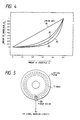
- Fig. 4 is a graphic representation in which the amounts of crosstalk ⁇ 1, ⁇ 2 and ⁇ 3 are each plotted with respect to the amount of crosstalk ⁇ .
- Fig. 4 As can be seen from Fig. 4, as the amount of crosstalk ⁇ is increased, recording density can be improved with respect to the same pickup. Event if the recording density is the same, it is possible to use a pickup which is inferior in light pickup (condense) performance, whereby production of pickups is facilitated.
- the amount ⁇ of crosstalk is substantially determined by the standards and design of the optical disk 5. If the values of the crosstalk ratios L and R differ from each other, it is possible to estimate the crosstalk ratios L and R from the output from the rotational position sensor 11 for detecting the angle of the optical disk 5 by utilizing the property that they accurately correspond to the angle of inclination of the optical disk 5. Otherwise, means for directly measuring the amount of crosstalk may be provided so that calculations are performed on the basis of the measurement result.
- the present invention can be similarly applied to a recording medium of any other type that has a track structure, such as an optical card, a magnetic recording medium or the like.
- a track structure such as an optical card, a magnetic recording medium or the like.
- the memory circuit 8 may utilize various kinds of memory devices such as semiconductor memory devices, optical memories or the like.
Landscapes
- Engineering & Computer Science (AREA)
- Signal Processing (AREA)
- Optical Recording Or Reproduction (AREA)
- Signal Processing For Digital Recording And Reproducing (AREA)
- Digital Magnetic Recording (AREA)
Applications Claiming Priority (2)
| Application Number | Priority Date | Filing Date | Title |
|---|---|---|---|
| JP1135565A JPH0785336B2 (ja) | 1989-05-29 | 1989-05-29 | 記録情報の読取り装置 |
| JP135565/89 | 1989-05-29 |
Publications (3)
| Publication Number | Publication Date |
|---|---|
| EP0400899A2 true EP0400899A2 (de) | 1990-12-05 |
| EP0400899A3 EP0400899A3 (de) | 1991-10-02 |
| EP0400899B1 EP0400899B1 (de) | 1995-06-21 |
Family
ID=15154787
Family Applications (1)
| Application Number | Title | Priority Date | Filing Date |
|---|---|---|---|
| EP90305672A Expired - Lifetime EP0400899B1 (de) | 1989-05-29 | 1990-05-24 | Gerät zur Wiedergabe von aufgezeichneten Daten |
Country Status (4)
| Country | Link |
|---|---|
| US (1) | US5084858A (de) |
| EP (1) | EP0400899B1 (de) |
| JP (1) | JPH0785336B2 (de) |
| DE (1) | DE69020243T2 (de) |
Cited By (8)
| Publication number | Priority date | Publication date | Assignee | Title |
|---|---|---|---|---|
| EP0402180A3 (de) * | 1989-06-12 | 1991-11-21 | Pioneer Electronic Corporation | Informationsaufzeichnungsgerät |
| EP0491301A1 (de) * | 1990-12-17 | 1992-06-24 | Sony Corporation | Gerät und Verfahren für die Wiedergabe von Signalen |
| EP0580876A4 (de) * | 1992-02-19 | 1994-10-19 | Sony Corp | Optisches aufzeichnungsmedium, aufzeichnungsmethode dafür, wiedergabemethode dafür und methode zur erzeugung eines spurfolgefehlersignal. |
| US5606545A (en) * | 1992-02-19 | 1997-02-25 | Sony Corporation | Reproducing apparatus having a detector for simultaneously scanning adjacent tracks of an optical recording medium |
| WO1997018559A1 (en) * | 1995-11-15 | 1997-05-22 | Zen Research N.V. | Method and apparatus for high speed optical storage device |
| WO1997018558A1 (en) * | 1995-11-15 | 1997-05-22 | Zen Research N.V. | Electronic track detection methods for apparatus for simultaneously reading multiple adjacent tracks of an optical disk |
| US6411573B1 (en) | 1998-02-20 | 2002-06-25 | Zen Research (Ireland), Ltd. | Multi-beam optical pickup |
| WO2002054394A3 (en) * | 2000-12-28 | 2002-11-21 | Darren Kraemer | Superresolution in periodic data storage media |
Families Citing this family (9)
| Publication number | Priority date | Publication date | Assignee | Title |
|---|---|---|---|---|
| JP2815998B2 (ja) * | 1990-03-14 | 1998-10-27 | 株式会社リコー | 光学的情報の再生方法 |
| JP3145751B2 (ja) * | 1991-12-03 | 2001-03-12 | パイオニア株式会社 | 光ピックアップ装置 |
| JPH07320269A (ja) * | 1994-05-23 | 1995-12-08 | Pioneer Electron Corp | クロストーク除去装置 |
| JPH07334931A (ja) * | 1994-06-10 | 1995-12-22 | Pioneer Electron Corp | クロストーク除去装置 |
| FR2727589B1 (fr) * | 1994-11-25 | 1997-01-03 | Thomson Csf | Dispositif et systeme de lecture |
| US5818806A (en) * | 1996-01-29 | 1998-10-06 | Calimetrics, Inc. | Method and apparatus for providing equalization for the reading of marks on optical data storage media |
| CA2249403C (en) * | 1996-03-22 | 2001-01-09 | Calimetrics, Inc. | Apparatus and methods for forming and use with variable pit depth optical recording media |
| CN101095189B (zh) * | 2004-06-03 | 2011-12-21 | 皇家飞利浦电子股份有限公司 | 包括rom标记的记录载体和用于检索rom标记的回放设备 |
| US8654471B2 (en) | 2011-09-30 | 2014-02-18 | Lsi Corporation | Disk-based storage device having write signal compensation for magnetization polarity of adjacent bits |
Family Cites Families (5)
| Publication number | Priority date | Publication date | Assignee | Title |
|---|---|---|---|---|
| BE890517A (fr) * | 1981-09-28 | 1982-01-18 | Staar Sa | Dispositif de memorisation d'images electroniques |
| US4520401A (en) * | 1982-04-16 | 1985-05-28 | Victor Company Of Japan, Ltd. | Digital video signal recording system and reproducing apparatus |
| JPS598104A (ja) * | 1982-07-05 | 1984-01-17 | Hitachi Ltd | 情報再生装置のクロスト−ク軽減方法 |
| JPS59139152A (ja) * | 1983-01-28 | 1984-08-09 | Canon Inc | 光情報再生方法および装置 |
| DE3372249D1 (en) * | 1983-03-30 | 1987-07-30 | Ibm Deutschland | Crosstalk compensation circuit for electro-optical scanning devices |
-
1989
- 1989-05-29 JP JP1135565A patent/JPH0785336B2/ja not_active Expired - Lifetime
-
1990
- 1990-05-22 US US07/526,746 patent/US5084858A/en not_active Expired - Lifetime
- 1990-05-24 DE DE69020243T patent/DE69020243T2/de not_active Expired - Fee Related
- 1990-05-24 EP EP90305672A patent/EP0400899B1/de not_active Expired - Lifetime
Cited By (18)
| Publication number | Priority date | Publication date | Assignee | Title |
|---|---|---|---|---|
| EP0402180A3 (de) * | 1989-06-12 | 1991-11-21 | Pioneer Electronic Corporation | Informationsaufzeichnungsgerät |
| EP0491301A1 (de) * | 1990-12-17 | 1992-06-24 | Sony Corporation | Gerät und Verfahren für die Wiedergabe von Signalen |
| US5295130A (en) * | 1990-12-17 | 1994-03-15 | Sony Corporation | Apparatus and method for signal reproduction |
| US5606545A (en) * | 1992-02-19 | 1997-02-25 | Sony Corporation | Reproducing apparatus having a detector for simultaneously scanning adjacent tracks of an optical recording medium |
| EP0829856A1 (de) * | 1992-02-19 | 1998-03-18 | Sony Corporation | Optisches Aufzeichnungsmedium, Aufzeichnungs- und Wiedergabemethode und Methode zur Erzeugung eines Spurfolgefehlersignals |
| US5557602A (en) * | 1992-02-19 | 1996-09-17 | Sony Corporation | Optical recording medium, recording and reproducing method and tracking error generating method |
| US5559786A (en) * | 1992-02-19 | 1996-09-24 | Sony Corporation | Information recording on a track by logical operation of the information on a neighboring track |
| US5602810A (en) * | 1992-02-19 | 1997-02-11 | Sony Corporation | Tracking error generating method using sampling of servo pits and switching of differential signals |
| EP0580876A4 (de) * | 1992-02-19 | 1994-10-19 | Sony Corp | Optisches aufzeichnungsmedium, aufzeichnungsmethode dafür, wiedergabemethode dafür und methode zur erzeugung eines spurfolgefehlersignal. |
| EP0829855A1 (de) * | 1992-02-19 | 1998-03-18 | Sony Corporation | Optisches Aufzeichnungsmedium, Aufzeichnungs- und Wiedergabemethode, und Methode zur Erzeugung eines Spurfolgefehlersignals |
| US5513161A (en) * | 1992-02-19 | 1996-04-30 | Sony Corporation | Optical recording medium, recording and reproducing method and tracking error generating method |
| US5633854A (en) * | 1992-02-19 | 1997-05-27 | Sony Corporation | Methods and apparatus for reproducing data recorded on an optical recording medium |
| US5684783A (en) * | 1992-02-19 | 1997-11-04 | Sony Corporation | Reproducing apparatus having a detector for simultaneously scanning adjacent tracks of an optical recording medium |
| WO1997018558A1 (en) * | 1995-11-15 | 1997-05-22 | Zen Research N.V. | Electronic track detection methods for apparatus for simultaneously reading multiple adjacent tracks of an optical disk |
| WO1997018559A1 (en) * | 1995-11-15 | 1997-05-22 | Zen Research N.V. | Method and apparatus for high speed optical storage device |
| US6411573B1 (en) | 1998-02-20 | 2002-06-25 | Zen Research (Ireland), Ltd. | Multi-beam optical pickup |
| WO2002054394A3 (en) * | 2000-12-28 | 2002-11-21 | Darren Kraemer | Superresolution in periodic data storage media |
| US6947363B2 (en) | 2000-12-28 | 2005-09-20 | R. J. Dwayne Miller | Superresolution in periodic data storage media |
Also Published As
| Publication number | Publication date |
|---|---|
| DE69020243D1 (de) | 1995-07-27 |
| EP0400899A3 (de) | 1991-10-02 |
| JPH031368A (ja) | 1991-01-08 |
| JPH0785336B2 (ja) | 1995-09-13 |
| EP0400899B1 (de) | 1995-06-21 |
| US5084858A (en) | 1992-01-28 |
| DE69020243T2 (de) | 1996-02-22 |
Similar Documents
| Publication | Publication Date | Title |
|---|---|---|
| EP0400899A2 (de) | Gerät zur Wiedergabe von aufgezeichneten Daten | |
| EP0881638B1 (de) | Gerät zur Unterscheidung optischer Platten | |
| JP2768741B2 (ja) | 情報記録装置 | |
| EP0279696B1 (de) | Zugriffsverfahren zu einer Spur eines Aufzeichnungsmediums im stillstehenden Zustand und Gerät dafür | |
| JPS61273779A (ja) | 情報再生装置 | |
| US5652746A (en) | Electronic track detection methods for apparatus for simultaneously reading multiple adjacent tracks of an optical disk | |
| JP3350072B2 (ja) | ピックアップ装置 | |
| EP0784322A2 (de) | Digitalsignal-Wiedergabegerät und Wiedergabeverfahren dafür | |
| US7969849B2 (en) | Method of reading a fourier hologram recorded on a holographic storage medium and a holographic storage system | |
| JP2916502B2 (ja) | 記録キャリヤ光学読取装置 | |
| US5128946A (en) | Information recording-reproducing method and apparatus | |
| US5446717A (en) | Optical disc and recording and reproducing method for an optical disc with a high density | |
| HUP9902497A2 (hu) | Optikai felvételi eljárás és készülék az eljárás foganatosítására | |
| JP2601174B2 (ja) | クロスト−クキャンセラのチャンネル間位相自動調整装置 | |
| EP0523334A2 (de) | Optisches Informationsaufzeichnungsmedium und Gerät zur Wiedergabe von Information aus dem Medium | |
| EP1081691B1 (de) | Gerät zum Messen der Exzentrizität einer Scheibe | |
| JP2003045058A (ja) | 光ディスク傾き検出装置 | |
| JPH11273084A5 (ja) | 光ディスク装置及び情報再生方法 | |
| EP0409574B1 (de) | Optisches Informationsaufzeichnungs- und -wiedergabegerät | |
| EP0913816A3 (de) | Vorrichtung zum lesen und beschreiben von optischem Aufzeichnungsträger | |
| US5812515A (en) | Apparatus and method for playing back optical recording having high linear density | |
| JP2611731B2 (ja) | トラック幅検査装置 | |
| US5491683A (en) | Optical information recording/reproducing method | |
| JPH08185632A (ja) | 光デイスク及び光デイスク装置 | |
| JP2964827B2 (ja) | トラッキング誤差検出装置 |
Legal Events
| Date | Code | Title | Description |
|---|---|---|---|
| PUAI | Public reference made under article 153(3) epc to a published international application that has entered the european phase |
Free format text: ORIGINAL CODE: 0009012 |
|
| AK | Designated contracting states |
Kind code of ref document: A2 Designated state(s): DE FR GB |
|
| PUAL | Search report despatched |
Free format text: ORIGINAL CODE: 0009013 |
|
| AK | Designated contracting states |
Kind code of ref document: A3 Designated state(s): DE FR GB |
|
| RHK1 | Main classification (correction) |
Ipc: G11B 20/22 |
|
| 17P | Request for examination filed |
Effective date: 19920327 |
|
| 17Q | First examination report despatched |
Effective date: 19931011 |
|
| GRAA | (expected) grant |
Free format text: ORIGINAL CODE: 0009210 |
|
| AK | Designated contracting states |
Kind code of ref document: B1 Designated state(s): DE FR GB |
|
| REF | Corresponds to: |
Ref document number: 69020243 Country of ref document: DE Date of ref document: 19950727 |
|
| ET | Fr: translation filed | ||
| PLBE | No opposition filed within time limit |
Free format text: ORIGINAL CODE: 0009261 |
|
| STAA | Information on the status of an ep patent application or granted ep patent |
Free format text: STATUS: NO OPPOSITION FILED WITHIN TIME LIMIT |
|
| 26N | No opposition filed | ||
| REG | Reference to a national code |
Ref country code: GB Ref legal event code: 746 Effective date: 19970418 |
|
| REG | Reference to a national code |
Ref country code: FR Ref legal event code: D6 |
|
| PGFP | Annual fee paid to national office [announced via postgrant information from national office to epo] |
Ref country code: DE Payment date: 20010514 Year of fee payment: 12 |
|
| PGFP | Annual fee paid to national office [announced via postgrant information from national office to epo] |
Ref country code: FR Payment date: 20010518 Year of fee payment: 12 |
|
| PGFP | Annual fee paid to national office [announced via postgrant information from national office to epo] |
Ref country code: GB Payment date: 20010523 Year of fee payment: 12 |
|
| REG | Reference to a national code |
Ref country code: GB Ref legal event code: IF02 |
|
| PG25 | Lapsed in a contracting state [announced via postgrant information from national office to epo] |
Ref country code: GB Free format text: LAPSE BECAUSE OF NON-PAYMENT OF DUE FEES Effective date: 20020524 |
|
| PG25 | Lapsed in a contracting state [announced via postgrant information from national office to epo] |
Ref country code: DE Free format text: LAPSE BECAUSE OF NON-PAYMENT OF DUE FEES Effective date: 20021203 |
|
| GBPC | Gb: european patent ceased through non-payment of renewal fee |
Effective date: 20020524 |
|
| PG25 | Lapsed in a contracting state [announced via postgrant information from national office to epo] |
Ref country code: FR Free format text: LAPSE BECAUSE OF NON-PAYMENT OF DUE FEES Effective date: 20030131 |
|
| REG | Reference to a national code |
Ref country code: FR Ref legal event code: ST |