EP0400921A2 - Tête de forage avec éléments de coupage pivotable concentrique et procédé de forage - Google Patents
Tête de forage avec éléments de coupage pivotable concentrique et procédé de forage Download PDFInfo
- Publication number
- EP0400921A2 EP0400921A2 EP90305734A EP90305734A EP0400921A2 EP 0400921 A2 EP0400921 A2 EP 0400921A2 EP 90305734 A EP90305734 A EP 90305734A EP 90305734 A EP90305734 A EP 90305734A EP 0400921 A2 EP0400921 A2 EP 0400921A2
- Authority
- EP
- European Patent Office
- Prior art keywords
- cutting element
- drilling
- drill bit
- mud
- cutting
- Prior art date
- Legal status (The legal status is an assumption and is not a legal conclusion. Google has not performed a legal analysis and makes no representation as to the accuracy of the status listed.)
- Withdrawn
Links
Images


Classifications
-
- E—FIXED CONSTRUCTIONS
- E21—EARTH OR ROCK DRILLING; MINING
- E21B—EARTH OR ROCK DRILLING; OBTAINING OIL, GAS, WATER, SOLUBLE OR MELTABLE MATERIALS OR A SLURRY OF MINERALS FROM WELLS
- E21B4/00—Drives for drilling, used in the borehole
- E21B4/16—Plural down-hole drives, e.g. for combined percussion and rotary drilling; Drives for multi-bit drilling units
Definitions
- This invention relates to a drill bit for use in a system for drilling deep wells, typically for the production of oil and gas, or for geothermal energy. It has as its main objective the attainment of faster rates of penetration (ROP) while drilling than can be achieved by known existing drilling methods without prejudice to drill bit life, in terms of the footage which can be drilled before drill bit performance deteriorates due to wear of the cutters. It is particularly suited to the drilling of the long straight sections of both vertical and deviated wells.
- a feature of this invention is that it makes maximum possible use of existing topside and downhole drilling equipment used for rotary drilling and for drilling by downhole mud motors or turbines.
- rotary drilling power is supplied to the drill bit by fixedly attaching the bit to an assembly connected to the bottom of the drill string and rotating the entire drill string by the input of power at the wellhead by means of a rotating table or power swivel.
- this method of drilling requires the rotation of a drill string whose length is frequently in excess of 10,000 feet, in the case of many oil and gas wells, the rotary drilling method is characterised by comparatively low rotational speed of the drill bit, generally 150 RPM or less. Comparatively high torque may be applied, the maximum torque being limited by considerations of fatigue or shear failure of the drill string. The limitation of speed results in a corresponding limit of power which can be applied to the drill string at the surface.
- the second method of drilling incorporates a mud motor or turbine attached to the bottom of the drill string to rotate the drill bit, and provision of a high pressure supply of drilling mud to the drill string.
- This high pressure mud is used to power the motor or turbine at base of the drill string so that it is not necessary to rotate the drill string to rotate the drill bit.
- drill string rotational friction losses are either eliminated or greatly reduced (should the drill string be rotated very slowly to improve directional control) thereby making mud motor or turbine drilling particularly suited to deviated wells and deeper sections of wells.
- a characteristic of mud motors and turbines is that the torque which they can deliver to the drill bit is generally much less than can be applied by rotary drilling. This torque limitation is offset by the higher rotational speed applied to the bit by motors and turbines. In the case of the latter, it is possible to apply a higher horsepower to the drill bit (albeit at a much lower torque) than with rotary drilling.
- An object of the present invention is to provide a means whereby advantageous features of both rotary drilling and either mud motors or turbodrills can be combined into one drilling system with higher power thus being made available to the drill bit, and a drill bit design which is capable or utilising this higher power for the achievement of higher penetration rates without prejudice to drill bit life.
- a drill bit assembly for use in a system for drilling a borehole of an oil or gas well, characterised in that said drill bit assembly comprises at least two concentric rotatable cutting elements of which one cutting element is adapted to be rotated at a rotational speed which is different from that of the other cutting element.
- the drill bit comprises two radially inner and outer cutting elements, the inner cutting element being adapted to be driven at a higher rotational speed than the outer cutting element.
- the inner and outer cutting elements are rotatable in the same direction.
- a drilling system for drilling a borehole of an oil or gas well comprising a rotatable drill string having a mud-driven power unit mounted adjacent the lower end thereof characterised in that there is provided a drill bit having a first radially outer cutting element mounted for rotation on rotation of the drill string, and a second radially inner cutting element rotatable by said mud-driven power unit.
- a method of drilling a borehole of an oil or gas well comprising rotating a drill string to effect rotation of a first cutting element located adjacent the lower end of said drill string, and simultaneously actuating a downhole motor or turbine to rotate a second cutting element located adjacent the lower end of said drill string.
- drilling mud is supplied at high pressure by a mud pump 1 via a power swivel or rotary table 2 at the well head to a drill string 3.
- a drill string 3 Attached to the bottom of the drill string 3 are drill collars 4 and a power unit in the form of a downhole drill motor or turbine 5 which is guided in the bore 6 of the well by stabilisers 7.
- the weight of the entire drill string and bottom hole assembly is supported by drill rig 8.
- a drill bit made up of two separate concentric components forming cutting elements.
- a radially inner annular cutting element 9 of the drill bit is attached to the lower end of drive shaft 10 of the downhole motor or turbine 5, while a radially outer annular cutting element 11 of the bit is attached to the lower end of an outer casing 12 of the motor or turbine 5.
- a small radial clearance 13 is maintained between the two cutting elements 9, 11 of the bit.
- Drilling mud can be fed via a hollow bore 10 a of the drive shaft 10 to nozzles 14 in the inner cutting element 9, and via labyrinths 15 between the drive shaft 10 and casing 12 to radial clearance 13. Mud can also be fed via duct means in the wall of the motor casing 12 to additional nozzles in the outer annular cutting element 11.
- cutter profiles 18 and 19 of the inner and outer drill bit cutting element 9 and 11 respectively may be arranged to overlap radially, with an axial clearance 20 between them, to prevent entry of rock cuttings into clearance 13.
- the cutting elements 9 and 11 are also substantially in transverse alignment.
- the drill string When the drilling system is in operation, the drill string is rotated, typically at speeds between 100 RPM and 150 RPM by the topside drive means 2. This causes the outer cutting element 11 of the drill bit to rotate at the same speed.
- the high pressure mud fed from the surface via drill string 3 to the motor or turbine 5, causes the output drive shaft 10 of the downhole motor or turbine 5 to rotate. It is generally preferable to rotate the output shaft 10 in the same direction as that of the drill string 5, so that the inner cutting element 9 of the drill bit is rotated in the same direction as the outer cutting element 11, but at a higher rotational speed.
- the rotational speed of the inner drill bit cutting element will generally be in the range 250 to 750 RPM, depending on the type of downhole motor used (i.e. positive displacement mud motor or turbine).
- Rotation of the two inner and outer cutting elements of the drill bit causes shearing or crushing of the rock formation and the formation cuttings are swept by the drilling mud into and up an annulus 21 between the drill string 3 and the bore 6 of the well, to the surface.
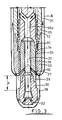
- FIG. 3 In a second embodiment of the invention as shown in Fig. 3, there is shown the lower end of a drilling system similar to that illustrated in Figs. 1 and 2. In this alternative embodiment like components are indicated by the same reference numerals as in Figs. 1 and 2.
- the drive shaft 10 of a downhole motor or turbine has fitted thereto at its free end, through an intermediate screw-threaded connector 29, the inner cutting element 30 of a drill bit.
- Drilling mud can be fed through the hollow bore 10 a of the drive shaft 10 and bore 31 in connector 29 to nozzles 37 in connector 29 and 32 in the inner cutting element 30 and via labyrinth 15 between the drive shaft 10 and the drill casing 12 and bearing clearance 35 between connector 39 and bearing 36 to a second radially outer drill bit cutting element 33.
- the radially outer cutting element 33 is carried on the lower end of the drill casing 12 of the motor or turbine.
- Bearing 36 is mounted within the bore of the outer cutting element 33.
- the outer cutting element 33 is of greater external diameter than the inner cutting element 30 and is spaced axially from the inner cutting element 30 by distance A.
- drilling mud is fed via the hollow bore 10 a and bore 31 to the inner cutting element 30 and via a passageway 34 and nozzles 37 to the outer cutting element 33.
- the inner cutting element 30 is caused to rotate at a greater rotational speed than the outer cutting element 33 and preferably in the same direction.
- the arrangement shown in Fig. 3 in which the outer cutting element 33 is axially distanced from the inner cutting element 30 has the principal advantage that for a given outer diameter of cutters 18, the diameter of the bore of the cutting element 33 in Fig. 3 can be arranged to be less than is possible with the cutting element 11 in Fig. 2, thus affording comparatively greater radial wall thickness and mechnical strength to cutting element 33.
Landscapes
- Engineering & Computer Science (AREA)
- Life Sciences & Earth Sciences (AREA)
- Geology (AREA)
- Mining & Mineral Resources (AREA)
- Mechanical Engineering (AREA)
- Physics & Mathematics (AREA)
- Environmental & Geological Engineering (AREA)
- Fluid Mechanics (AREA)
- General Life Sciences & Earth Sciences (AREA)
- Geochemistry & Mineralogy (AREA)
- Earth Drilling (AREA)
Applications Claiming Priority (2)
| Application Number | Priority Date | Filing Date | Title |
|---|---|---|---|
| GB8912396 | 1989-05-30 | ||
| GB898912396A GB8912396D0 (en) | 1989-05-30 | 1989-05-30 | Drill bit for use in a system for drilling oil and gas wells |
Publications (2)
| Publication Number | Publication Date |
|---|---|
| EP0400921A2 true EP0400921A2 (fr) | 1990-12-05 |
| EP0400921A3 EP0400921A3 (fr) | 1991-09-11 |
Family
ID=10657580
Family Applications (1)
| Application Number | Title | Priority Date | Filing Date |
|---|---|---|---|
| EP19900305734 Withdrawn EP0400921A3 (fr) | 1989-05-30 | 1990-05-25 | Tête de forage avec éléments de coupage pivotable concentrique et procédé de forage |
Country Status (4)
| Country | Link |
|---|---|
| EP (1) | EP0400921A3 (fr) |
| BR (1) | BR9002563A (fr) |
| GB (1) | GB8912396D0 (fr) |
| NO (1) | NO902381L (fr) |
Cited By (2)
| Publication number | Priority date | Publication date | Assignee | Title |
|---|---|---|---|---|
| EP0770759A3 (fr) * | 1995-10-26 | 1997-07-02 | Camco Drilling Group Ltd | Ensemble de forage pour forer des puits dans des formations souterraines |
| US9932772B2 (en) | 2011-09-20 | 2018-04-03 | Halliburton Energy Services, Inc. | Systems and methods for limiting torque transmission |
Family Cites Families (4)
| Publication number | Priority date | Publication date | Assignee | Title |
|---|---|---|---|---|
| US4267893A (en) * | 1979-08-27 | 1981-05-19 | Union Oil Company Of California | Dual-rotating eccentric drilling apparatus and method |
| DE3408246C2 (de) * | 1984-03-07 | 1986-07-31 | Witte Bohrtechnik GmbH, 3060 Stadthagen | Vortriebseinrichtung zum Herstellen unterirdischer Hohlräume nach dem Rohrvorpreßverfahren |
| GB8608857D0 (en) * | 1986-04-11 | 1986-05-14 | Drilex Aberdeen Ltd | Drilling |
| US4862974A (en) * | 1988-12-07 | 1989-09-05 | Amoco Corporation | Downhole drilling assembly, apparatus and method utilizing drilling motor and stabilizer |
-
1989
- 1989-05-30 GB GB898912396A patent/GB8912396D0/en active Pending
-
1990
- 1990-05-25 EP EP19900305734 patent/EP0400921A3/fr not_active Withdrawn
- 1990-05-29 NO NO90902381A patent/NO902381L/no unknown
- 1990-05-30 BR BR909002563A patent/BR9002563A/pt unknown
Cited By (2)
| Publication number | Priority date | Publication date | Assignee | Title |
|---|---|---|---|---|
| EP0770759A3 (fr) * | 1995-10-26 | 1997-07-02 | Camco Drilling Group Ltd | Ensemble de forage pour forer des puits dans des formations souterraines |
| US9932772B2 (en) | 2011-09-20 | 2018-04-03 | Halliburton Energy Services, Inc. | Systems and methods for limiting torque transmission |
Also Published As
| Publication number | Publication date |
|---|---|
| GB8912396D0 (en) | 1989-07-12 |
| EP0400921A3 (fr) | 1991-09-11 |
| NO902381D0 (no) | 1990-05-29 |
| BR9002563A (pt) | 1991-08-13 |
| NO902381L (no) | 1990-12-03 |
Similar Documents
| Publication | Publication Date | Title |
|---|---|---|
| US6470977B1 (en) | Steerable underreaming bottom hole assembly and method | |
| CA2604002C (fr) | Forage avec tubage | |
| US6269892B1 (en) | Steerable drilling system and method | |
| US9187955B2 (en) | Locking clutch for downhole motor | |
| US7334649B2 (en) | Drilling with casing | |
| US7735581B2 (en) | Locking clutch for downhole motor | |
| US7562725B1 (en) | Downhole pilot bit and reamer with maximized mud motor dimensions | |
| US20100126773A1 (en) | Drilling apparatus and system for drilling wells | |
| AU2002245623A1 (en) | Steerable underreaming bottom hole assembly and method | |
| EP0770759A2 (fr) | Ensemble de forage pour forer des puits dans des formations souterraines | |
| US11655678B2 (en) | Mud motor bearing assembly for use with a drilling system | |
| EP0400921A2 (fr) | Tête de forage avec éléments de coupage pivotable concentrique et procédé de forage | |
| US5988272A (en) | Apparatus and method for milling a well casing | |
| SU794139A1 (ru) | Способ бурени скважин | |
| AU2013228003B2 (en) | Locking clutch for downhole motor | |
| Herbert | Turbodrilling in the Hot-Hole Environment | |
| CN116624100A (zh) | 随钻单弯扩孔装置 | |
| Herbert | Turbodrilling in the geothermal environment | |
| Inglis | Turbodrills |
Legal Events
| Date | Code | Title | Description |
|---|---|---|---|
| PUAI | Public reference made under article 153(3) epc to a published international application that has entered the european phase |
Free format text: ORIGINAL CODE: 0009012 |
|
| AK | Designated contracting states |
Kind code of ref document: A2 Designated state(s): AT BE CH DE DK ES FR GB GR IT LI LU NL SE |
|
| PUAL | Search report despatched |
Free format text: ORIGINAL CODE: 0009013 |
|
| AK | Designated contracting states |
Kind code of ref document: A3 Designated state(s): AT BE CH DE DK ES FR GB GR IT LI LU NL SE |
|
| 17P | Request for examination filed |
Effective date: 19920221 |
|
| 17Q | First examination report despatched |
Effective date: 19930129 |
|
| STAA | Information on the status of an ep patent application or granted ep patent |
Free format text: STATUS: THE APPLICATION IS DEEMED TO BE WITHDRAWN |
|
| 18D | Application deemed to be withdrawn |
Effective date: 19930609 |