EP0400933A2 - Bandkassette - Google Patents
Bandkassette Download PDFInfo
- Publication number
- EP0400933A2 EP0400933A2 EP90305766A EP90305766A EP0400933A2 EP 0400933 A2 EP0400933 A2 EP 0400933A2 EP 90305766 A EP90305766 A EP 90305766A EP 90305766 A EP90305766 A EP 90305766A EP 0400933 A2 EP0400933 A2 EP 0400933A2
- Authority
- EP
- European Patent Office
- Prior art keywords
- tape
- cassette
- cassette case
- lid
- front surface
- Prior art date
- Legal status (The legal status is an assumption and is not a legal conclusion. Google has not performed a legal analysis and makes no representation as to the accuracy of the status listed.)
- Granted
Links
Images


Classifications
-
- G—PHYSICS
- G11—INFORMATION STORAGE
- G11B—INFORMATION STORAGE BASED ON RELATIVE MOVEMENT BETWEEN RECORD CARRIER AND TRANSDUCER
- G11B23/00—Record carriers not specific to the method of recording or reproducing; Accessories, e.g. containers, specially adapted for co-operation with the recording or reproducing apparatus ; Intermediate mediums; Apparatus or processes specially adapted for their manufacture
- G11B23/02—Containers; Storing means both adapted to cooperate with the recording or reproducing means
- G11B23/04—Magazines; Cassettes for webs or filaments
- G11B23/08—Magazines; Cassettes for webs or filaments for housing webs or filaments having two distinct ends
- G11B23/087—Magazines; Cassettes for webs or filaments for housing webs or filaments having two distinct ends using two different reels or cores
- G11B23/08707—Details
- G11B23/08785—Envelopes
-
- G—PHYSICS
- G11—INFORMATION STORAGE
- G11B—INFORMATION STORAGE BASED ON RELATIVE MOVEMENT BETWEEN RECORD CARRIER AND TRANSDUCER
- G11B23/00—Record carriers not specific to the method of recording or reproducing; Accessories, e.g. containers, specially adapted for co-operation with the recording or reproducing apparatus ; Intermediate mediums; Apparatus or processes specially adapted for their manufacture
- G11B23/02—Containers; Storing means both adapted to cooperate with the recording or reproducing means
- G11B23/04—Magazines; Cassettes for webs or filaments
- G11B23/08—Magazines; Cassettes for webs or filaments for housing webs or filaments having two distinct ends
- G11B23/087—Magazines; Cassettes for webs or filaments for housing webs or filaments having two distinct ends using two different reels or cores
- G11B23/08707—Details
- G11B23/08735—Covers
Definitions
- the present invention relates to a tape cassette, and particularly to a tape cassette which is desirable for a magnetic recording/reproducing device such as a video tape recorder or the like.
- a conventional tape cassette to be inserted into a magnetic tape device such as a video tape recorder (which will be referred to as VTR hereinafter) or the like has a construction that front and inner lids provided on a front surface of a case cover a magnetic tape extended on the front surface of the case (for example, refer to Japanese Laid-Open Patent Publication No. 63-175279).
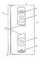
- Fig. 28 is a perspective view of the tape cassette of the prior art
- Figs. 29 and 30 are sectional views of an important portion of the tape cassette of the prior art.
- an opening 61 is provided on a front surface of the tape cassette 64 substantially in a whole width of the cassette 64.
- a magnetic tape 59 is stretched over the opening 61 and is usually covered with front and inner lids 58 and 57.
- the front lid 58 is free to rotate about a supporting point pin 65.
- a coil spring 66 is fitted to the supporting point pin 65 and always urges the front lid 58 toward a closing rotation direction.
- a pair of brackets 67 are provided at an upper and inner side of the front lid 58.
- a pair of supporting pins 60 provided at both left and right ends of the inner lid 57 are inserted into the brackets 67, and the inside lid 57 can freely rotate about the supporting pins 60.
- a pair of guiding pins 55 provided at both ends of the inner lid 57 are inserted into a guiding groove 56, and are free to slide thereon.
- a locking member 50 is rotatably provided at the cassette case 68.
- a plate spring 70 is fitted to a rear side of the locking member 50 and urges the locking member 50 toward a forward rotation direction.
- a protrusion 52 provided on a side plate 54 of the front lid 58 is engaged with a click 53 of the locking member 50, thus the rotation of the front lid 58 is prevented.
- the tape cassette 64 usually prevents the front lid 58 from carelessly opening by means of the locking member 50.
- the locking 50 rotates in the D direction against the force of the plate spring 70 by means of a lock releasing member 71 provided at the VTR, thus the protrusion 52 becomes disengaged from the click 53 to enable the front lid 58 to rotate as shown in Fig. 30.
- the front lid 58 is moved in the E direction as shown in Fig. 30, the front lid 58 is opened upward.
- the supporting pins 60 on the inner lid 57 are moved upward about the supporting point pin 65 and the guiding pins 55 are guided along the guiding groove 56.
- the lids 58 and 57 are opened.
- the above is the opening operations for inserting the tape cassette 64 into the VTR, and is reversed when the tape cassette 64 is being taken out.
- a length from the tape surface extended over the front surface of the cassette to the front lid rotation supporting point is larger than that from the cassette bottom surface, so that a wider cassette opening is necessary and the cassette becomes bigger considering the woundable tape length.
- An object of the present invention is to provide a tape cassette which can prevent tape damages due to an inner lid with a narrower cassette opening and has an excellent dust protection by utilizing a simple construction.
- Another object of the present invention is to provide a tape cassette which can have smaller stroke for opening lids of the cassette and can realize a thinner VTR deck by providing a protrusion engaged with a cutout of the cassette case and a upwardly and downwardly movable moving member for opening the lids.
- Still another object of the present invention is to provide a tape cassette which can surely locate the tape cassette in an appropriate position in a cassette holder with a simple construction even when tape cassettes of different sizes are inserted into the same cassette holder.
- a tape cassette of the present invention comprises a pair of tape reels which wound a tape thereon and have each end of the tape attached hereto respectively, a cassette case which has the tape reels therein and has the tape extended at a front surface thereof, an opening provided at an inside of the tape extended at the front surface, a front lid which is pivotally supported on side surfaces of the cassette case and covers a front surface of the tape extended at the front surface of the cassette case in accordance with rotation, and an inner lid which is pivotally supported on the front lid and covers a back surface of the tape in accordance with rotation, wherein a rotation supporting point (rotation axis) of the front lid is located at a portion where the distance from a bottom surface of the cassette case is equal to or larger than that from the tape back surface extended at the front surface of the cassette case.
- the cassette case of the present invention can prevent damages on thc tape due to the inner lid even with a small opening by utilizing a simple construction, can make smaller a dead space which is occupied by the front lid when the front lid is opened, and can excellently avoid dust on the tape.
- the present invention can provide a tape cassette which is characterized by that damages on the tape can be prevented even with the small cassette opening by utilizing a simple construction, dust on the tape can be effectively avoided, a stroke for opening the lids of the cassette case can be made shorter, a VTR deck is made thinner by providing a protrusion which is to be engaged with a cutout of the cassette case or by providing a moving member, which moves upwardly and downwardly, for opening the lids, and a tape cassette can be located in an appropriate position in one cassette holder even when tape cassettes of different sizes are inserted into the same cassette holder.
- a tape cassette of one embodiment of the present invention is described in details hereinafter referring to Figs. 1 to 7.
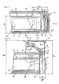
- Fig. 1 is a plan view of one embodiment of the present invention without a top cassette case, a front lid, and an inner lid
- Fig. 2 is a plan view of a tape cassette
- Figs. 3 and 4 are sectional views taken along a line X-X
- Fig. 5 is a perspective view of a main portion of an engaging portion of the front and inner lids
- Figs. 6, 7 are sectional views taken along a line Y-Y.
- a tape cassette 1 has a bottom cassette case 2 and a top cassette case 3 engaged with each other to form a flat cassette case.
- This cassette case houses two cassette reals 4a, 4b aligned in a same plane, and a magnetic tape 5.
- the cassette reels 4a, 4b have a starting or finishing end of the magnetic tape 5 fixed thereto respectively, and have the magnetic tape 5 wound thereon.
- a front lid 6 covers top and front surfaces of the magnetic tape 5 and has a substantially U-shape as shown in Figs. 3 and 4 which show sectional views taken along the line X-X when the lid 6 is open or closed.
- a pair of front lid rotation supporting shafts 6a, 6b provided at side plates at left and right ends of the front lid 6 are pivotally supported on the cassette cases 2, 3.
- the front lid 6 rotates about the rotation supporting shafts 6a, 6b toward an upper surface 3a of the top cassette case 3, and opens.
- the front lid 6 is always urged in the closing direction by means of a front lid urging spring 7 provided at the rotation supporting shaft 6b.
- This spring 7 is made of a torsion coil spring. One end thereof is supported on the top cassette case 3 and the other end thereof is supported on a pin 6c provided at the front lid rotation supporting shaft 6b.
- An inner lid 8 covers a back surface of the magnetic tape 5 at openings 9a, 9b.
- the inner lid 8 has a pair of inner lid rotation supporting shafts 8a protruding left and right, and the inner lid rotation supporting shafts 8a are pivotally supported on a pair of left and right bearings 6e of brackets 6d integrally provided at the front lid 6.
- the inner lid 8 can rotate about the rotation supporting shafts 8a.
- Guiding grooves 2a are provided both at left and right ends of the openings 9a, 9b of the bottom cassette case 2 and guide guiding pins 8b of substantially both ends of the inner lid 8 thereon.
- the openings 9a, 9b are utilized for having a post (not shown) inserted therein, and this post leads the magnetic tape 5 out of the cassette cases 2, 3.
- the magnetic tape 5 is extended in front of and in parallel with a front surface 13 of the cassette cases 2, 3 having a distance Sm therebetween and is guided by guiding posts 10a, 10b provided both at left and right ends of the cassette cases 2, 3, a guiding post 11, and a guiding roller 12 provided in the cassette case 2, 3.
- a pair of front lid rotation supporting shafts 6a, 6b of the front lid 6 are located at positions where there is a distance XL from the magnetic tape 5 surface extended in front of and in parallel with the front surface 13 and there is a distance YL from a bottom surface 2c of the bottom cassette case 2. And that XL ⁇ YL.
- the magnetic tape 5 is wound on the cassette reels 4a, 4b to form tape rolls 14a, 14b.
- a lighthouse 15 made of photodiode emits a beam to a light receiving element (not shown) in order to detect starting and finishing ends of the magnetic tape 5.
- the lighthouse 15 is inserted into the tape cassette 1 through an insertion hole 16.
- the beam from the lighthouse 15 inserted into this insertion hole 16 is lead from insides of the cassette cases 2, 3 to outsides via light paths 17a, 17b.
- the light paths 17a, 17b are arranged in asymmetric angular positions.
- a restricting plate 18 is provided in the openings 9a, 9b, is adjacent to the back surface of the magnetic tape 5 extended in front of the tape cassette 1, and is standing apparoximately straight up from a base portion 19 of the bottom cassette case 2 substantially in parallel with the magnetic tape 5.
- a cutout 8c of a U-shape is provided at a position facing the restricting plate 18 of the inner lid 8 and engages with the restricting plate 18.
- a position 6f of the front lid 6 and a portion 8d of the inner lid 8 contact each other to cover the substantially whole magnetic tape 5 extended at the front surface of the tape cassette 1. Nevertheless, there is a little space among the front surface 18a of the restricting plate 18, the portion 6f of the front lid, and the cutout 8c of the back surface 8.
- the front and inner lids 6, 8 cover the restricting plate 18 as well as the magnetic tape 5.
- Position determining holes 20a, 20b are guiding holes of the tape cassette 1 and are used when the tape cassette 1 is inserted into VTR (not shown).
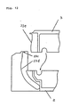
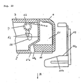
- FIG. 8 A plan view when the front and inner lids are assembled is shown in Fig. 8, and sectional views taken along the line Z-Z when the lids are closed or open are shown in Figs. 9, 10.
- first and second cutouts 21, 21a are provided at the cassette cases 2, 3, and lid opening portions 22a, 22b of a lid opening member 22 provided at VTR are inserted into the cutout 21.
- the cutouts 21, 21a have shapes which do not interfere with the light path 17b from the lighthouse 15.
- a bracket 6g is formed integrally at an inside of the front lid 6 and is provided at a position facing the cutouts 21, 21a of the top and bottom cassette cases 3, 2.
- a groove 23 is defined by the top and bottom cassette cases 3, 2, has a V-shape including portions 23a, 23b, and is arranged at a position which does not interfere with the light path 17b from the lighthouse 15.
- a lid opening moving member 24 moves upward and downward in the cutouts 21, 21a.
- the lid opening moving member 24 has a shaft 24a at a substantially central portion thereof.
- One end of the member 24 is a guiding pin 24b, and the other end thercof a free end 24c.
- the shaft 24a is rotatably and pivotally supported on a bearing 6h of the bracket 6g.
- the guiding pin 24b is guided by the groove 23.
- the free end 24c is located at a position substantially equal to the front surface of the front lid 6 when the lids are closed, and is engaged with a cutout 6i of the font lid 6.
- a locking member 25 is engaged with a locking portion 6j provided at a side plate of the front lid 6 and locks the front lid 6 so that the lid 6 is prevented from accidentally opening when the tape cassette 1 is not inserted in VTR and damages on the magnetic tape 5 are avoided.
- a locking member urging spring 6j always urges the locking member 25 in the direction in which the locking member 25 comes to be engaged with the locking portion 6j of the front lid 6.
- Reel brakes 27a, 27b prevent the tape 5 from being loosed due to accidental rotation of the cassette reels 4a, 4b on which the magnetic tape 5 is wound.
- the reel brakes 27a, 27b rotate about shafts 28a, 28b provided at the cassette cases 2, 3 and are always urged in the direction in which tip ends thereof come to be engaged with the cassette reels 4a, 4b by means of an urging spring (not shown).
- An accidental erase prevention switch 19 is provided at a substantially rectangular chamber defined by engagement of the cassette cases 2, 3 and can move freely left and right.
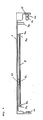
- Fig. 13 is a back surface view of the tape cassette of one embodiment of the present invention
- Fig. 14 is a side surface view seen from the J1 direction.
- Fig. 15 is a plan view of a cassette holder by which the tape cassette is fitted to VTR (not shown)
- Fig. 16 is a front view of the cassette holder
- Fig. 17 is a side view of a stage portion seen from the J2 direction
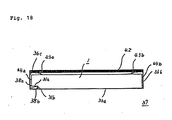
- Fig. 18 is a front view when the tape cassette of the present invention is inserted into the cassette holder
- Fig. 19 is a front view when a usual standard tape cassette is inserted into the cassette holder.
- the tape cassette 1 is larger than a usual standard tape cassette 30 by B dimension in their width.
- the width of the usual standard tape cassette 30 is equal to A dimension.
- a tape cassette guiding stepped portion 31 is formed at the back surface of the tape cassette 1 and has B dimension in its width and C dimension in its depth.
- a first taper 32 widens in its Width as it goes toward the front and a second taper 33 diverges in its depth.
- Reel stand insertion holes 34a, 34b at both supplying and winding sides of the reels 4a, 4b are also shown.
- a misinsertion preventing groove 35 prevents the tape cassette 1 from being inserted inappropriately upside down or in opposite directions.
- a bottom holder 36 is provided at a cassette holder 37 and has a substantially U-shape.
- a cassette holder stepped portion 38 is provided at an inside of the bottom cassette holder 36. Top and side surfaces 38a, 38b of the cassette holder stepped portion 38 are engaged with portions 31a and 31b of the tape cassette guiding stage portion 31 of the tape cassette 1 and guide the tape cassette 1.
- Tapers 39. 40 widens in their width and height as they go toward a rear surface of the cassette holder 37 along the cassette holder stepped portion 38.
- a misinsertion preventing click 41 prevents the tape cassette 1 from being inserted inappropriately upside down or in opposite direction.
- a top cassette holder 42 is fixed to the bottom cassette holder 36 by means of fixing members (not shown) to form the cassette holder 37 and has plate springs 43a, 43b at a bottom surface thereof.
- the plate springs 43a, 43b urge the tape cassette 1 or the usual standard tape cassette 30 inserted into the cassette holder 37 downward.
- Fig. 3 is a view when the lids are open, and the magnetic tape 5 stretched over the openings 9a, 9b is usually covered with the front lid 6 and the inner lid 8.
- the side surface 36b of the bottom cassette holder 36 and the side surface 38b of the cassette holder stepped portion 38 guide a side surface 44b of the tape cassette 1 and the side surface 31b of the tape cassette guiding stepped portion 31 of the tape cassette 1 in the width of the tape cassette.
- the tape cassette 1 is urged downward by means of the plate springs 43a, 43b, and a bottom surface 2c of the bottom cassette case 2 contacts and is restrictively guided by a top surface 36a of the bottom cassette holder 36.
- the top surface 38a of the cassette holder stage portion 38 does not contact the top surface 31a of the tape cassette guiding stepped portion 31.
- the tape cassette 1 is guided and restricted by the side surface 36b of the bottom cassette holder 36 and the side surface 38b of the cassette holder stepped portion 38, and dimensions are determined so that a side surface 44a of the tape cassette 1 is not guided and restricted by a side surface 36c of the bottom cassette holder 36.
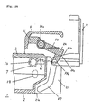
- the lid opening member 22 provided at VTR comes to be located inside the front lid 6 and also contacts the lid opening moving member 24 which is to be engaged with the first and second cutouts 21, 21a of the cassette cases 2, 3, so that there is generated a force in the lid opening moving member 24 to move and rotate the front lid 6 clockwise about the front lid rotation supporting shafts 6a, 6b. Further movement of the front lid 6 in the direction of the arrow III will open the front lid 6 upward about the supporting shafts 6a, 6b against the front lid urging spring 7.
- the inside lid 8 rotates integrally with the front lid 6 about the inside lid supporting shaft 8a while being guided and restricted by a pair of guiding grooves 1a, lb provided at both the left and right side plates of the bottom cassette case 2, thus the state shown in Figs. 4, 7, 10 is achieved.
- Fig. 11 shows that when the lid opening moving member 24 and the front lid 6 are opened excessively by accident, a contacting portion 23c at an upper portion of the groove 23 contacts the guiding pin 24b of the moving member 24 to restrict further opening of the lid 6.
- a reel brake releasing member (not shown) provided at VTR makes the reel brakes 27a, 27b rotating in the direction departing from the cassette reels 4a, 4b to release stopping the cassette reels 4a, 4b.
- the reel stands (not shown) in VTR come to support the cassette. reels 4a, 4b, and the reels 4a, 4b are free to rotate.
- the lighthouse 15, for detecting the starting and finishing ends of the magnetic tape 5, provided at VTR and a loading post (not shown) for winding the magnetic tape 5 on a rotation cylinder (not shown) are inserted into the lighthouse insertion hole 16 and the openings 9a, 9b.
- the front lid 6 and the inner lid 8 rotate in the closing direction by means of urging forces of the front lid urging spring 7. If the tape cassette 1 is influenced by some kind of shock at this time and the magnetic tape 5 is loosed, the magnetic tape 5 is restricted by the restricting plate 18 not to be loosed backward too much, so that damages on the tape 5 due to contact of the inner lid 8 with the magnetic tape 5 can be prevented.
- the stage portion of the tape cassette 1 is provided only at a lower end of one side surface.
- the stage portion can be provided at both side surfaces or at an upper end or the like for example.
- the substantially V-shape groove 23 is divided into two, top cassette case 3 side and bottom cassette case 2 side, at substantially the central portion thereof, but the position and shape are not limited to the above.
- the groove 23 can be divided so that one side 23d of the groove 23 is provided at the bottom cassette case 2 and the other side 23e is provided at the top cassette case 3.
- the lid opening mechanism of the first embodiment is constructed by the moving member 24.
- a simple protrusion 49 shown in Figs. 20, 21, is used in thc second embodiment.
- the protrusion 49 provided at the inside of the front lid 6 in the second embodiment is made of an elastic material, and the front lid 6 is restricted to rotate counterclockwise at a state shown in Fig. 22 by means of a stopper (not shown) provided at the top cassette case 3.
- a front lid elastic protrusion 50 absorbs the error by means of elastic distortion in the arrow IV direction, so that a rotation amount of the front lid 6 does not change.
- a fourth embodiment is shown in Figs. 23, 24.
- a first protrusion 51 is provided at the inside of the front lid 6.
- a second protrusion 52 is slidablly supported on an inside of the first protrusion 51.
- the second protrusion 52 is always urged in the direction engaging with the second cutout 21a by means of a compression coil spring 53.
- the compression coil spring 53 absorbs the error of the second protrusion 52 by means of elastic distortion in the arrow V direction, so that a rotation amount of the front lid 6 does not change.
- the fifth embodiment is shown in Figs. 25, 26.
- the front lid 6 is restricted to rotate counterclockwise at the state shown in Fig. 25 by means of a stopper (not shown) formed at the top cassette case 3, and if a lid opening surface 22b of the lid opening member 22 has an error in the height direction, a lid opening moving member 54 only rotates about a rotation pin 54a against an urging member 55 and a rotation amount of the front lid 6 does not change.
- a relationship between the rotation axis position (XL, YL) and a lid opening maximum height of the tape cassette 1 when the lids are open in the tape cassette 1 which has a small space Sm of the openings 9a, 9b from the magnetic tape 5 surface and has a construction in which the tape 5 is usually protected from dust by means of the front and inside lids 6, 8 is shown in Fig. 27.
- the maximum lid opening height are classified into two, a maximum height Hmax brought by a front upper end 6K of the front lid 6 with rotation of the front lid 6 and a maximum height Pmax brought by a front lower and 6L of the front lid 6.
- the rotation axis position of the front lid 6 where XL ⁇ YL is achieved is necessary in order to have low maximum lid opening heights (Hmax, Pmax) and to make sure that he magnetic tape 5 is surely protected from dust by means of the front and inside lids 6, 8.
Landscapes
- Packaging Of Annular Or Rod-Shaped Articles, Wearing Apparel, Cassettes, Or The Like (AREA)
Applications Claiming Priority (6)
| Application Number | Priority Date | Filing Date | Title |
|---|---|---|---|
| JP134909/89 | 1989-05-29 | ||
| JP1134909A JPH02312085A (ja) | 1989-05-29 | 1989-05-29 | テープカセット |
| JP1266908A JPH03127391A (ja) | 1989-10-12 | 1989-10-12 | テープカセット |
| JP266908/89 | 1989-10-12 | ||
| JP30873/90 | 1990-02-09 | ||
| JP2030873A JPH03235279A (ja) | 1990-02-09 | 1990-02-09 | テープカセット |
Publications (3)
| Publication Number | Publication Date |
|---|---|
| EP0400933A2 true EP0400933A2 (de) | 1990-12-05 |
| EP0400933A3 EP0400933A3 (de) | 1992-08-05 |
| EP0400933B1 EP0400933B1 (de) | 1995-07-05 |
Family
ID=27287124
Family Applications (1)
| Application Number | Title | Priority Date | Filing Date |
|---|---|---|---|
| EP90305766A Expired - Lifetime EP0400933B1 (de) | 1989-05-29 | 1990-05-25 | Bandkassette |
Country Status (4)
| Country | Link |
|---|---|
| US (1) | US5308014A (de) |
| EP (1) | EP0400933B1 (de) |
| KR (1) | KR930006811B1 (de) |
| DE (1) | DE69020643T2 (de) |
Cited By (3)
| Publication number | Priority date | Publication date | Assignee | Title |
|---|---|---|---|---|
| EP0501719A3 (en) * | 1991-02-25 | 1992-12-09 | Sony Corporation | Tape cassette |
| EP0529964A3 (en) * | 1991-08-27 | 1994-12-28 | Sony Corp | Tape cassette |
| US6115084A (en) * | 1994-12-27 | 2000-09-05 | Seiko Epson Corporation | Projection-type display apparatus |
Families Citing this family (2)
| Publication number | Priority date | Publication date | Assignee | Title |
|---|---|---|---|---|
| JP3031813B2 (ja) * | 1994-02-04 | 2000-04-10 | ティーディーケイ株式会社 | テープカセット |
| JP2000331451A (ja) * | 1999-05-18 | 2000-11-30 | Fuji Photo Film Co Ltd | 磁気テープカセット |
Family Cites Families (31)
| Publication number | Priority date | Publication date | Assignee | Title |
|---|---|---|---|---|
| US3437028A (en) * | 1967-01-25 | 1969-04-08 | Orests B Berlings | Photographic film cassettes and parts thereof |
| US3537376A (en) * | 1967-11-20 | 1970-11-03 | Eastman Kodak Co | Light lock for the entrance/exit passageway of a container for light-sensitive material |
| US3645385A (en) * | 1969-06-20 | 1972-02-29 | Eastman Kodak Co | Openable cartridge for facilitating egress and ingress of strip material |
| US4173319A (en) * | 1975-12-13 | 1979-11-06 | Victor Company Of Japan, Limited | Magnetic tape cassette |
| US4068809A (en) * | 1976-09-20 | 1978-01-17 | The Singer Company | Filmstrip cartridge with film lock |
| NL165598C (nl) * | 1978-05-09 | 1981-04-15 | Philips Nv | Magneetbandcassette. |
| JPS57210489A (en) * | 1981-06-22 | 1982-12-24 | Sony Corp | Tape cassette |
| US4457473A (en) * | 1982-06-04 | 1984-07-03 | Data Electronics, Inc. | Tape cartridge housing |
| JPS58215770A (ja) * | 1982-06-10 | 1983-12-15 | Atlas:Kk | テ−プ用容器 |
| JPS5982379U (ja) * | 1982-11-20 | 1984-06-04 | 日立マクセル株式会社 | テ−プカ−トリツジ |
| US4608616A (en) * | 1982-12-08 | 1986-08-26 | Victor Company Of Japan, Ltd. | Tape cassette having a lock mechanism for locking a tape protecting lid |
| JPS605485A (ja) * | 1983-06-22 | 1985-01-12 | Hitachi Maxell Ltd | テ−プカ−トリツジ |
| US4520970A (en) * | 1983-10-03 | 1985-06-04 | Kennedy Company | Cartridge tape drive having vacuum auto-threading |
| US4527755A (en) * | 1983-10-17 | 1985-07-09 | Minnesota Mining And Manufacturing Company | Hinged visor-type door for tape cassette |
| JPS60121580A (ja) * | 1983-12-02 | 1985-06-29 | Matsushita Electric Ind Co Ltd | テ−プカセット |
| JPS60214488A (ja) * | 1984-04-10 | 1985-10-26 | Matsushita Electric Ind Co Ltd | テ−プカセツト |
| JPH0413796Y2 (de) * | 1985-01-07 | 1992-03-30 | ||
| JPH0454628Y2 (de) * | 1985-06-03 | 1992-12-22 | ||
| US4685016A (en) * | 1985-08-20 | 1987-08-04 | Ampex Corporation | Door operating mechanism for a cassette usable in a magnetic tape recorder |
| JP2604718B2 (ja) * | 1986-04-11 | 1997-04-30 | 松下電器産業株式会社 | テープカセツト |
| US4757399A (en) * | 1986-05-21 | 1988-07-12 | Eastman Kodak Company | Flexible cassette for use with a reel periphery driven transport |
| JPS6318271A (ja) * | 1986-07-10 | 1988-01-26 | Nissan Motor Co Ltd | 圧電型力学量センサ |
| JPS6316829A (ja) * | 1986-07-10 | 1988-01-23 | Masahito Kaneko | シングルエツジ刃物の製造法 |
| JPS6316824A (ja) * | 1986-07-10 | 1988-01-23 | Matsushita Giken Kk | コイル材のジグザグ送り装置 |
| US4844377A (en) * | 1986-07-18 | 1989-07-04 | Matsushita Electric Industrial Co., Ltd. | Tape cassette |
| KR960010333B1 (ko) * | 1986-07-26 | 1996-07-30 | 니뽕 빅터 가부시끼가이샤 | 소형 테이프 카세트 |
| JPS6391884U (de) * | 1986-12-04 | 1988-06-14 | ||
| JPH0521734Y2 (de) * | 1987-06-18 | 1993-06-03 | ||
| JP2600215B2 (ja) * | 1987-11-11 | 1997-04-16 | ソニー株式会社 | テープカセット |
| US4836465A (en) * | 1988-01-29 | 1989-06-06 | Cal R&D, Inc. | Magnetic tape transport system |
| JPH06132284A (ja) * | 1992-10-22 | 1994-05-13 | Kawasaki Steel Corp | 半導体装置の保護膜形成方法 |
-
1990
- 1990-05-25 DE DE69020643T patent/DE69020643T2/de not_active Expired - Fee Related
- 1990-05-25 EP EP90305766A patent/EP0400933B1/de not_active Expired - Lifetime
- 1990-05-29 KR KR1019900007779A patent/KR930006811B1/ko not_active Expired - Fee Related
-
1992
- 1992-04-28 US US07/875,594 patent/US5308014A/en not_active Expired - Lifetime
Cited By (4)
| Publication number | Priority date | Publication date | Assignee | Title |
|---|---|---|---|---|
| EP0501719A3 (en) * | 1991-02-25 | 1992-12-09 | Sony Corporation | Tape cassette |
| US5279476A (en) * | 1991-02-25 | 1994-01-18 | Sony Corporation | Tape cassette lid having projection for preventing tape pinching |
| EP0529964A3 (en) * | 1991-08-27 | 1994-12-28 | Sony Corp | Tape cassette |
| US6115084A (en) * | 1994-12-27 | 2000-09-05 | Seiko Epson Corporation | Projection-type display apparatus |
Also Published As
| Publication number | Publication date |
|---|---|
| KR930006811B1 (ko) | 1993-07-23 |
| DE69020643D1 (de) | 1995-08-10 |
| EP0400933B1 (de) | 1995-07-05 |
| EP0400933A3 (de) | 1992-08-05 |
| DE69020643T2 (de) | 1996-02-22 |
| US5308014A (en) | 1994-05-03 |
| KR900018995A (ko) | 1990-12-22 |
Similar Documents
| Publication | Publication Date | Title |
|---|---|---|
| EP0778567B1 (de) | Plattenkassette | |
| RU2066482C1 (ru) | Кассета с магнитной лентой | |
| US6125012A (en) | Recording medium cartridge with a twin-coiled torsional spring-biased shutter | |
| EP0533463B1 (de) | Plattenkassette mit Falschaufzeichnungsschutzmechanismus | |
| EP0444623B1 (de) | Bandkassette-Lademechanismus | |
| KR940006883B1 (ko) | 카트리지셔터 개폐장치 | |
| EP0400933B1 (de) | Bandkassette | |
| EP0473437B1 (de) | Bandkassette | |
| EP0574944A2 (de) | Bandkassette mit Verschluss | |
| US5005092A (en) | Shutter opening device | |
| US5506738A (en) | Tape cassette with tape guide support structure | |
| EP0501719B1 (de) | Bandkassette | |
| EP0452148A2 (de) | Bandkassette | |
| US7780106B2 (en) | Recording tape cartridge | |
| RU2066481C1 (ru) | Кассета для носителя записи | |
| US6320724B1 (en) | Floppy disk drive unit with contact preventing mechanism | |
| KR19980024872A (ko) | 크기가 다른 복수 종류의 카세트 장착시 카세트 콘테이너 | |
| US5237479A (en) | Tape cassette with slidable cover | |
| US5999363A (en) | Cassette housing having cassette stoppers to prevent mis-insertion | |
| US6683752B2 (en) | Tape cassette | |
| JPH03235279A (ja) | テープカセット | |
| KR0136707B1 (ko) | 테이프 카세트(Tape cassette) | |
| US6282058B1 (en) | Belt-type tape cartridge with increased magnetic tape capacity | |
| JP2629431B2 (ja) | テープカセット | |
| JPH02122459A (ja) | カセットホルダー装置 |
Legal Events
| Date | Code | Title | Description |
|---|---|---|---|
| PUAI | Public reference made under article 153(3) epc to a published international application that has entered the european phase |
Free format text: ORIGINAL CODE: 0009012 |
|
| AK | Designated contracting states |
Kind code of ref document: A2 Designated state(s): DE FR GB |
|
| PUAL | Search report despatched |
Free format text: ORIGINAL CODE: 0009013 |
|
| AK | Designated contracting states |
Kind code of ref document: A3 Designated state(s): DE FR GB |
|
| 17P | Request for examination filed |
Effective date: 19930128 |
|
| 17Q | First examination report despatched |
Effective date: 19931015 |
|
| GRAA | (expected) grant |
Free format text: ORIGINAL CODE: 0009210 |
|
| AK | Designated contracting states |
Kind code of ref document: B1 Designated state(s): DE FR GB |
|
| REF | Corresponds to: |
Ref document number: 69020643 Country of ref document: DE Date of ref document: 19950810 |
|
| ET | Fr: translation filed | ||
| PLBE | No opposition filed within time limit |
Free format text: ORIGINAL CODE: 0009261 |
|
| STAA | Information on the status of an ep patent application or granted ep patent |
Free format text: STATUS: NO OPPOSITION FILED WITHIN TIME LIMIT |
|
| 26N | No opposition filed | ||
| REG | Reference to a national code |
Ref country code: GB Ref legal event code: IF02 |
|
| PGFP | Annual fee paid to national office [announced via postgrant information from national office to epo] |
Ref country code: DE Payment date: 20070517 Year of fee payment: 18 |
|
| PGFP | Annual fee paid to national office [announced via postgrant information from national office to epo] |
Ref country code: GB Payment date: 20070523 Year of fee payment: 18 |
|
| PGFP | Annual fee paid to national office [announced via postgrant information from national office to epo] |
Ref country code: FR Payment date: 20070510 Year of fee payment: 18 |
|
| GBPC | Gb: european patent ceased through non-payment of renewal fee |
Effective date: 20080525 |
|
| REG | Reference to a national code |
Ref country code: FR Ref legal event code: ST Effective date: 20090119 |
|
| PG25 | Lapsed in a contracting state [announced via postgrant information from national office to epo] |
Ref country code: FR Free format text: LAPSE BECAUSE OF NON-PAYMENT OF DUE FEES Effective date: 20080602 Ref country code: DE Free format text: LAPSE BECAUSE OF NON-PAYMENT OF DUE FEES Effective date: 20081202 |
|
| PG25 | Lapsed in a contracting state [announced via postgrant information from national office to epo] |
Ref country code: GB Free format text: LAPSE BECAUSE OF NON-PAYMENT OF DUE FEES Effective date: 20080525 |