EP0400950B1 - Zündkerze - Google Patents
Zündkerze Download PDFInfo
- Publication number
- EP0400950B1 EP0400950B1 EP90305797A EP90305797A EP0400950B1 EP 0400950 B1 EP0400950 B1 EP 0400950B1 EP 90305797 A EP90305797 A EP 90305797A EP 90305797 A EP90305797 A EP 90305797A EP 0400950 B1 EP0400950 B1 EP 0400950B1
- Authority
- EP
- European Patent Office
- Prior art keywords
- firing tip
- powder compact
- insulator
- iridium powder
- tip
- Prior art date
- Legal status (The legal status is an assumption and is not a legal conclusion. Google has not performed a legal analysis and makes no representation as to the accuracy of the status listed.)
- Expired - Lifetime
Links
Images



Classifications
-
- H—ELECTRICITY
- H01—ELECTRIC ELEMENTS
- H01T—SPARK GAPS; OVERVOLTAGE ARRESTERS USING SPARK GAPS; SPARKING PLUGS; CORONA DEVICES; GENERATING IONS TO BE INTRODUCED INTO NON-ENCLOSED GASES
- H01T13/00—Sparking plugs
- H01T13/20—Sparking plugs characterised by features of the electrodes or insulation
- H01T13/39—Selection of materials for electrodes
-
- H—ELECTRICITY
- H01—ELECTRIC ELEMENTS
- H01T—SPARK GAPS; OVERVOLTAGE ARRESTERS USING SPARK GAPS; SPARKING PLUGS; CORONA DEVICES; GENERATING IONS TO BE INTRODUCED INTO NON-ENCLOSED GASES
- H01T21/00—Apparatus or processes specially adapted for the manufacture or maintenance of spark gaps or sparking plugs
- H01T21/02—Apparatus or processes specially adapted for the manufacture or maintenance of spark gaps or sparking plugs of sparking plugs
Definitions
- This invention relates to spark plugs, in particular the improvements of their resistance to spark erosion.
- firing tips have been manufactured individually from precious metals such as platinum or platinum-iridium based alloys. These firing tips may be columnar or laminar, and respectively bonded to a center electrode and an outer electrode by welding. The columnar tip, however, requires a great amount of precious metal thus raising manufacturing costs. On the other hand, the use of a laminar tip leads to a waste of precious metal because the tip is punched from a sheet of the metal thus reducing the yield by 30 percent.
- a tip which is made of a Pt-Ir alloy has a melting point of more than 2300 degrees Celsius, so that it is difficult to machine the tip unless it is at an extremely high temperature.
- the Pt-Ir tip which is alloyed by means of a metallurgical process, is ductile but fragile, and cracks readily occur on the tip at the time of machining, thus making it very difficult to machine the tip into a complex shape.
- the tip may also be shaped by means of electric discharge machining, but this takes a long time to finish because of its high melting point.
- US-A-3 466 158 discloses a method of manufacturing a spark plug for an internal combustion engine, comprising the steps of providing a cylindrical metallic shell and placing a tubular ceramic insulator concentrically therein, placing a centre electrode concentrically within the tubular insulator, forming a firing tip from iridium material, and metallurgically bonding the firing tip to the front end of the centre electrode to form a spark gap between the firing tip and an outer electrode which extends from the metallic shell.
- FR-A-1,490,828 discloses a method of making a spark plug firing tip by sintering a compact of ruthenium powder.
- FR-A-1 490 828 further discloses a method of manufacturing a spark plug for an internal combustion engine, comprising the steps of preparing a ruthenium-iridium powder compact, forming a firing tip from the ruthenium-iridium powder compact, and sintering the ruthenium-iridium powder in a reducing atmosphere at a temperature of 1500°C to impart a density of 89% of theoretical to the ruthenium-iridium powder compact so as to provide spark-erosion resistance.
- DE-A-3,038,649 discloses a method of making a spark plug firing tip but using a compact of platinum powder.
- a spark plug for an internal combustion engine comprising the steps of:
- the present invention also provides a spark plug comprising:
- the firing tip is made from an iridium powder compact which may be compressed by means of metallic die press, thus lending itself to simple mass production, at reduced costs, with minimal waste of precious metal. Further, the use of powder metallurgy makes it possible to form firing tips of complex shapes which metallurgical processes may be unable to achieve.
- a spark plug 1 which is to be incorporated into an internal combustion engine.
- the spark plug 1 has a cylindrical metallic shell 3 having a nut portion 3a and a thread portion 5 at its outer surface.
- a tubular insulator 2 is concentrically enclosed which is made of alumina and nitride based ceramics such as aluminum nitride (AlN) and silicon nitride (Si 3 N 4 ).
- the interior of the insulator 2 has as an axial bore 8 in which a terminal electrode 10 and a center electrode 7 are concentrically enclosed. These electrodes 10, 7 are linearly aligned by way of an electrically conductive glass sealant 9 which is encapsulated into the axial bore 8.
- the center electrode 7 is made of a metallic material, but may be made of an electrically conductive ceramic powder or a metal-coated ceramic body.
- a front end of the center electrode 7 is terminated somewhat short of the front end of the insulator 2.
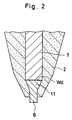
- a firing tip 6 is inserted and sintered simultaneously at the insulator, and metallurgically bonded to the front end of the centre electrode 7 by means of an electrical resistant welding (Wd) as shown in Fig. 2.
- Wd electrical resistant welding
- a front end of the firing tip 6 extends somewhat beyond the front end of the insulator 2 so as to provide a spark gap (Ga) between the tip 6 and an outer electrode 4 mounted on the metallic shell 5.
- the firing tip 6 is made from an iridium powder compact body by means of a metallic die press, C.I.P., extrusion or injection. Then, the compact body is degreased, and sintered at a temperature of more than 2000 degrees Celsius in a vacuum, or an inert reductive atmosphere, so that the density of the powder compact is more than 90 percent, thus improving the spark-erosion resistance.
- the firing tip 6 has a frusto-conically shaped stem 11 at a side in which the tip 6 is metallurgically bonded to the insulator 2. As shown in Fig. 3, the firing tip 6 measures 2.0 mm in length (C), and measures 0.8 mm, and 1.2 mm at its diameters (a), (b) at its stem 11. The stem 11 measures 0.5 mm in height (d) with a 45 degree taper of its stem 11.
- Table 1 shows a relationship between relative press forming density, sintering atmosphere, sintering conditions and density of a sintered compact body.
- the sintered compact body is placed in air at the time of sintering, the iridium of the compact body is oxidized to produce a black iridium oxide leading to volatilization.
- the compact body is then sintered at a temperature ranging from 1700 to 2200 degrees Celsius, and preferably sintered at more than 2000 degrees Celsius.
- Fig. 6 is a graph showing the comparative erosion between a sintered compact body and a metallurgically processed ingot iridium tip at different densities of sintered compact.
- the value 100 is taken to be the erosion of a metallurgically processed iridium tip.
- the comparative erosion of the firing tip decreases with the increase of the density of the sintered compact body.
- a spark erosion experiment is carried out with the sample (K) at Table 2 employed.
- the sample is an iridium powder compact which is compressed by means of a die press, so that the press forming density ratio is 66.3 percent.
- the compact body, thus compressed is primarily sintered at 2200 degrees Celsius in a hydrogen atmosphere for 60 minutes, so that the density of the compact body is 92.5 percent.
- the compact body is secondarily sintered at 1400 degrees Celsius in an argon atmosphere for 60 minutes, and shaped as shown in Fig. 3 by means of a hot isostatic hydraulic press.
- sample press forming density ratio (%) primary sintering atmosphere sintering condition °C ⁇ min. density of compact body (%) A 66.4 vacuum 1300 ⁇ 30 75.6 B 66.4 ditto 1700 ⁇ 60 86.7 C 67.3 hydrogen 1700 ⁇ 60 87.7 D 66.4 ditto 1800 ⁇ 60 87.9 E 66.4 ditto 1900 ⁇ 60 89.0 F 66.4 ditto 2000 ⁇ 60 92.1 G 66.3 ditto 2200 ⁇ 60 92.5 sample secondary sintering sintering condition °C ⁇ min.
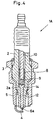
- the firing tip 6a is formed into a columnar shape, and measures 0.5 mm in diameter (e), and 1.5 mm in length (f).
- a center electrode 12 is made of a copper core clad by a nickel alloy.
- the center electrode 12 is encapsulated in the axial bore 8 with the glass sealant 9, and has a flanged head 14 at its upper end to engage against a stepped portion 2a of the inner wall of the insulator 2.
- the front end face of the center electrode 12 has a recess 13 into which the firing tip 6a is fitted and securely attached at the center electrode 12 by means of a metallurgical bond (L) such as an electron beam welding or a laser welding. It is noted that the firing tip 6a may also be used in igniter plugs in general.
- L metallurgical bond
Landscapes
- Engineering & Computer Science (AREA)
- Manufacturing & Machinery (AREA)
- Spark Plugs (AREA)
Claims (6)
- Verfahren zur Herstellung einer Zündkerze für einen Verbrennungsmotor, wobei das Verfahren die folgenden Schritte umfaßt:Vorsehen eines zylinderförmigen Metallgehäuses und Anordnen eines rohrförmigen Keramikisolators konzentrisch darin; undAnordnen einer Mittelelektrode konzentrisch in dem rohrförmigen Isolator; gekennzeichnet durch die weiteren Schritte:Herstellen eines Iridium-Pulver-Preßlings;Bilden einer Zündspitze aus dem Iridium-Pulver-Preßling;Sintern des Iridium-Pulver-Preßlings in einem Vakuum oder in einer nicht oxidierenden oder reduzierenden Atmosphäre bei einer Temperatur in dem Bereich von 2000 bis 2200°C, um dem Iridium-Pulver-Preßling eine Dichte von mindestens 90% der theoretischen Dichte zu verleihen, um diesen mit einem Funkenerosionswiderstand zu versehen, undmetallurgisches Verbinden der Zündspitze mit dem vorderen Ende der Mittelelektrode zur Bildung einer Funkenstrecke zwischen der Zündspitze und einer Außenelektrode, die sich ausgehend von dem Metallgehäuse erstreckt.
- Verfahren nach Anspruch 1, mit dem folgenden Schritt:Einführen der Zündspitze in das vordere Ende des rohrförmigen Isolators, wobei das Sintern der Zündspitze gleichzeitig an dem Isolator durchgeführt wird, wobei die Zündspitze einen Schaft aufweist, damit die Zündspitze an der richtigen Stelle angeordnet wird, wenn die Zündspitze in den rohrförmigen Isolator eingeführt wird.
- Verfahren nach Anspruch 1, wobei die vordere Endfläche der Mittelelektrode mit einer Aussparung versehen ist, in die die Zündspitze eingepaßt wird, und der metallurgische Verbindungsschritt unter Verwendung des Elektronenstrahlschweißens oder des Laserschweißens durchgeführt wird.
- Verfahren nach Anspruch 1, wobei das Sintern des Iridium-Pulver-Preßlings bei etwa 2000°C über einen Zeitraum von 60 Minuten durchgeführt wird und das Verfahren den weiteren Schritt des Sinterns des Iridium-Pulver-Preßlings bei etwa 1400°C über einen Zeitraum von 60 Minuten in einer Argonatmosphäre mit Hilfe eines isostatischen Heißpressvorgangs umfaßt.
- Zündkerze mit:einem zylinderförmigen Metallgehäuse;einem rohrförmigen Keramikisolator, der konzentrisch in dem Gehäuse angeordnet ist, undeiner Mittelelektrode, die konzentrisch in dem Isolator angeordnet ist, gekennzeichnet durcheine Zündspitze, die metallurgisch mit der Mittelelektrode verbunden ist, wobei die Zündspitze aus einem gesinterten Iridium-Pulver-Preßling hergestellt ist und eine Dichte aufweist, die größer als 90% der theoretischen Dichte ist.
- Zündkerze nach Anspruch 5, bei der eine vordere Endfläche der Mittelelektrode eine Aussparung aufweist, in der die Zündspitze eingepaßt und mit Hilfe des metallurgischen Verbindens, wie z.B. Elektronenstrahlschweißen oder Laserschweißen, an der Mittelelektrode befestigt werden soll.
Applications Claiming Priority (3)
| Application Number | Priority Date | Filing Date | Title |
|---|---|---|---|
| JP132760/89 | 1989-05-29 | ||
| JP1132760A JPH07109783B2 (ja) | 1989-05-29 | 1989-05-29 | 内燃機関用スパークプラグ |
| JP13276089 | 1989-05-29 |
Publications (2)
| Publication Number | Publication Date |
|---|---|
| EP0400950A1 EP0400950A1 (de) | 1990-12-05 |
| EP0400950B1 true EP0400950B1 (de) | 2000-02-09 |
Family
ID=15088918
Family Applications (1)
| Application Number | Title | Priority Date | Filing Date |
|---|---|---|---|
| EP90305797A Expired - Lifetime EP0400950B1 (de) | 1989-05-29 | 1990-05-29 | Zündkerze |
Country Status (3)
| Country | Link |
|---|---|
| EP (1) | EP0400950B1 (de) |
| JP (1) | JPH07109783B2 (de) |
| DE (1) | DE69033451T2 (de) |
Cited By (3)
| Publication number | Priority date | Publication date | Assignee | Title |
|---|---|---|---|---|
| US7282844B2 (en) | 2003-09-17 | 2007-10-16 | Denso Corporation | High performance, long-life spark plug |
| US8485857B1 (en) | 2012-01-24 | 2013-07-16 | General Electric Company | Method of producing a spark gap for an electrode support using sacrificial material |
| US8912713B2 (en) | 2012-01-24 | 2014-12-16 | General Electric Company | Method of producing an electrode support using brazing |
Families Citing this family (10)
| Publication number | Priority date | Publication date | Assignee | Title |
|---|---|---|---|---|
| JP3000955B2 (ja) * | 1996-05-13 | 2000-01-17 | 株式会社デンソー | スパークプラグ |
| DE19745165A1 (de) * | 1997-10-13 | 1999-04-15 | Volkswagen Ag | Zündkerze mit beschichteter Kerzenisolatorbohrung |
| DE10103045A1 (de) | 2001-01-24 | 2002-07-25 | Bosch Gmbh Robert | Verfahren zur Herstellung einer Zündkerzenelektrode |
| JP2006260988A (ja) * | 2005-03-17 | 2006-09-28 | Ngk Spark Plug Co Ltd | スパークプラグ |
| US7443089B2 (en) | 2006-06-16 | 2008-10-28 | Federal Mogul World Wide, Inc. | Spark plug with tapered fired-in suppressor seal |
| JP5492244B2 (ja) | 2012-04-09 | 2014-05-14 | 日本特殊陶業株式会社 | 点火プラグ |
| JP6010569B2 (ja) | 2014-02-24 | 2016-10-19 | 日本特殊陶業株式会社 | スパークプラグ |
| US10418787B2 (en) * | 2017-05-11 | 2019-09-17 | Denso International America, Inc. | Ground electrode pad for spark plug |
| DE102018101512B4 (de) | 2018-01-24 | 2020-03-19 | Federal-Mogul Ignition Gmbh | Verfahren zum Herstellen einer Elektrodenanordnung, Elektrodenanordnung und Zündkerze |
| DE102018105941B4 (de) | 2018-03-14 | 2021-09-02 | Federal-Mogul Ignition Gmbh | Zündkerzen-Zündspitze, Zündkerzenanordnung und Verfahren zum Herstellen einer Zündkerzen-Zündspitze |
Citations (3)
| Publication number | Priority date | Publication date | Assignee | Title |
|---|---|---|---|---|
| GB1099387A (en) * | 1965-08-25 | 1968-01-17 | Johnson Matthey Co Ltd | Improvements in and relating to sparking plug electrodes |
| US4427915A (en) * | 1979-10-13 | 1984-01-24 | Ngk Spark Plug Co. Ltd. | Spark plug and the process for production thereof |
| EP0353196A1 (de) * | 1988-07-28 | 1990-01-31 | Champion Spark Plug Belgium S.A. | Zusammensetzungen von elektroleitendem Cermet für Zündungs- und Heizungsanordnungen |
Family Cites Families (5)
| Publication number | Priority date | Publication date | Assignee | Title |
|---|---|---|---|---|
| US3466158A (en) * | 1966-01-10 | 1969-09-09 | Int Nickel Co | Compound precious metal article having layer containing iridium or ruthenium |
| FR1490828A (fr) * | 1966-08-24 | 1967-08-04 | Johnson | électrode pour bougie d'allumage |
| US3548239A (en) * | 1968-09-03 | 1970-12-15 | Champion Spark Plug Co | Spark plug electrode construction |
| JPS6188478A (ja) * | 1984-10-05 | 1986-05-06 | 日本特殊陶業株式会社 | スパ−クプラグの中心電極 |
| JPS62226592A (ja) * | 1986-03-28 | 1987-10-05 | 日本特殊陶業株式会社 | 点火プラグ |
-
1989
- 1989-05-29 JP JP1132760A patent/JPH07109783B2/ja not_active Expired - Lifetime
-
1990
- 1990-05-29 EP EP90305797A patent/EP0400950B1/de not_active Expired - Lifetime
- 1990-05-29 DE DE1990633451 patent/DE69033451T2/de not_active Expired - Lifetime
Patent Citations (3)
| Publication number | Priority date | Publication date | Assignee | Title |
|---|---|---|---|---|
| GB1099387A (en) * | 1965-08-25 | 1968-01-17 | Johnson Matthey Co Ltd | Improvements in and relating to sparking plug electrodes |
| US4427915A (en) * | 1979-10-13 | 1984-01-24 | Ngk Spark Plug Co. Ltd. | Spark plug and the process for production thereof |
| EP0353196A1 (de) * | 1988-07-28 | 1990-01-31 | Champion Spark Plug Belgium S.A. | Zusammensetzungen von elektroleitendem Cermet für Zündungs- und Heizungsanordnungen |
Cited By (3)
| Publication number | Priority date | Publication date | Assignee | Title |
|---|---|---|---|---|
| US7282844B2 (en) | 2003-09-17 | 2007-10-16 | Denso Corporation | High performance, long-life spark plug |
| US8485857B1 (en) | 2012-01-24 | 2013-07-16 | General Electric Company | Method of producing a spark gap for an electrode support using sacrificial material |
| US8912713B2 (en) | 2012-01-24 | 2014-12-16 | General Electric Company | Method of producing an electrode support using brazing |
Also Published As
| Publication number | Publication date |
|---|---|
| JPH07109783B2 (ja) | 1995-11-22 |
| DE69033451D1 (de) | 2000-03-16 |
| JPH031475A (ja) | 1991-01-08 |
| DE69033451T2 (de) | 2000-06-08 |
| EP0400950A1 (de) | 1990-12-05 |
Similar Documents
| Publication | Publication Date | Title |
|---|---|---|
| EP1298768B1 (de) | Zündkerze | |
| KR101562410B1 (ko) | 스파크 플러그 및 그 제조방법 | |
| EP0400950A1 (de) | Zündkerze | |
| KR101562411B1 (ko) | 스파크 플러그 및 그 제조방법 | |
| EP0588495B1 (de) | Zündkerze und sein Herstellungsverfahren | |
| EP1628375B1 (de) | Zündkerze | |
| KR20100103673A (ko) | 내연기관용 스파크 플러그 및 그 제조방법 | |
| EP0474351B1 (de) | Massenelektrode für Zündkerze und ihr Herstellungsverfahren | |
| JPH0737677A (ja) | スパークプラグ | |
| EP2028736B1 (de) | Zündkerze für einen Verbrennungsmotor | |
| EP2133967A2 (de) | Zündkerze | |
| EP3306762A1 (de) | Zündkerze | |
| EP1677400B1 (de) | Zündkerze | |
| US5774780A (en) | Process for production of a shaped part | |
| EP0353196A1 (de) | Zusammensetzungen von elektroleitendem Cermet für Zündungs- und Heizungsanordnungen | |
| EP2658050A1 (de) | Zündkerze | |
| GB2060773A (en) | Spark igniter | |
| EP2752949B1 (de) | Zündkerze | |
| EP3200291B1 (de) | Zündkerze | |
| JP2002198158A (ja) | スパークプラグの製造方法及びスパークプラグ | |
| JP3272488B2 (ja) | スパークプラグの製造方法 | |
| CN115038803B (zh) | 火花塞用贵金属电极头、火花塞用电极和火花塞 | |
| JP2005285464A (ja) | スパークプラグの製造方法 | |
| JPH06338376A (ja) | スパークプラグ用電極 | |
| JPH0582236A (ja) | 多極スパークプラグ |
Legal Events
| Date | Code | Title | Description |
|---|---|---|---|
| PUAI | Public reference made under article 153(3) epc to a published international application that has entered the european phase |
Free format text: ORIGINAL CODE: 0009012 |
|
| AK | Designated contracting states |
Kind code of ref document: A1 Designated state(s): DE FR GB |
|
| 17P | Request for examination filed |
Effective date: 19910227 |
|
| 17Q | First examination report despatched |
Effective date: 19930504 |
|
| GRAG | Despatch of communication of intention to grant |
Free format text: ORIGINAL CODE: EPIDOS AGRA |
|
| GRAG | Despatch of communication of intention to grant |
Free format text: ORIGINAL CODE: EPIDOS AGRA |
|
| GRAH | Despatch of communication of intention to grant a patent |
Free format text: ORIGINAL CODE: EPIDOS IGRA |
|
| GRAH | Despatch of communication of intention to grant a patent |
Free format text: ORIGINAL CODE: EPIDOS IGRA |
|
| GRAA | (expected) grant |
Free format text: ORIGINAL CODE: 0009210 |
|
| AK | Designated contracting states |
Kind code of ref document: B1 Designated state(s): DE FR GB |
|
| REF | Corresponds to: |
Ref document number: 69033451 Country of ref document: DE Date of ref document: 20000316 |
|
| ET | Fr: translation filed | ||
| PLBE | No opposition filed within time limit |
Free format text: ORIGINAL CODE: 0009261 |
|
| STAA | Information on the status of an ep patent application or granted ep patent |
Free format text: STATUS: NO OPPOSITION FILED WITHIN TIME LIMIT |
|
| 26N | No opposition filed | ||
| REG | Reference to a national code |
Ref country code: GB Ref legal event code: IF02 |
|
| PGFP | Annual fee paid to national office [announced via postgrant information from national office to epo] |
Ref country code: GB Payment date: 20050525 Year of fee payment: 16 |
|
| PG25 | Lapsed in a contracting state [announced via postgrant information from national office to epo] |
Ref country code: GB Free format text: LAPSE BECAUSE OF NON-PAYMENT OF DUE FEES Effective date: 20060529 |
|
| GBPC | Gb: european patent ceased through non-payment of renewal fee |
Effective date: 20060529 |
|
| PGFP | Annual fee paid to national office [announced via postgrant information from national office to epo] |
Ref country code: FR Payment date: 20090515 Year of fee payment: 20 Ref country code: DE Payment date: 20090527 Year of fee payment: 20 |
|
| PG25 | Lapsed in a contracting state [announced via postgrant information from national office to epo] |
Ref country code: DE Free format text: LAPSE BECAUSE OF EXPIRATION OF PROTECTION Effective date: 20100529 |