EP0400957B1 - Tragbares Spritzgerät - Google Patents
Tragbares Spritzgerät Download PDFInfo
- Publication number
- EP0400957B1 EP0400957B1 EP90305809A EP90305809A EP0400957B1 EP 0400957 B1 EP0400957 B1 EP 0400957B1 EP 90305809 A EP90305809 A EP 90305809A EP 90305809 A EP90305809 A EP 90305809A EP 0400957 B1 EP0400957 B1 EP 0400957B1
- Authority
- EP
- European Patent Office
- Prior art keywords
- discharge
- nozzle
- cap
- outer tube
- discharge nozzle
- Prior art date
- Legal status (The legal status is an assumption and is not a legal conclusion. Google has not performed a legal analysis and makes no representation as to the accuracy of the status listed.)
- Expired - Lifetime
Links
- 239000007921 spray Substances 0.000 claims abstract description 33
- 239000000463 material Substances 0.000 claims abstract description 29
- 230000005484 gravity Effects 0.000 claims abstract description 5
- 238000007599 discharging Methods 0.000 claims description 8
- 238000005507 spraying Methods 0.000 claims description 8
- 239000011345 viscous material Substances 0.000 claims description 8
- 238000004891 communication Methods 0.000 claims description 2
- 239000000203 mixture Substances 0.000 abstract description 10
- 230000007246 mechanism Effects 0.000 abstract description 6
- 230000001105 regulatory effect Effects 0.000 abstract description 3
- 230000008878 coupling Effects 0.000 abstract description 2
- 238000010168 coupling process Methods 0.000 abstract description 2
- 238000005859 coupling reaction Methods 0.000 abstract description 2
- 230000001276 controlling effect Effects 0.000 abstract 1
- 230000008439 repair process Effects 0.000 description 5
- 238000000034 method Methods 0.000 description 3
- 230000008859 change Effects 0.000 description 2
- 150000001875 compounds Chemical class 0.000 description 2
- 238000010276 construction Methods 0.000 description 2
- 239000012530 fluid Substances 0.000 description 2
- 238000009435 building construction Methods 0.000 description 1
- 238000002788 crimping Methods 0.000 description 1
- 230000000694 effects Effects 0.000 description 1
- 238000007689 inspection Methods 0.000 description 1
- 238000005259 measurement Methods 0.000 description 1
- 238000012986 modification Methods 0.000 description 1
- 230000004048 modification Effects 0.000 description 1
- 230000008520 organization Effects 0.000 description 1
- 239000003973 paint Substances 0.000 description 1
- 239000011505 plaster Substances 0.000 description 1
- 238000002360 preparation method Methods 0.000 description 1
- 230000008569 process Effects 0.000 description 1
- 230000000135 prohibitive effect Effects 0.000 description 1
- 238000005476 soldering Methods 0.000 description 1
- 238000007592 spray painting technique Methods 0.000 description 1
Images


Classifications
-
- B—PERFORMING OPERATIONS; TRANSPORTING
- B05—SPRAYING OR ATOMISING IN GENERAL; APPLYING FLUENT MATERIALS TO SURFACES, IN GENERAL
- B05B—SPRAYING APPARATUS; ATOMISING APPARATUS; NOZZLES
- B05B7/00—Spraying apparatus for discharge of liquids or other fluent materials from two or more sources, e.g. of liquid and air, of powder and gas
- B05B7/14—Spraying apparatus for discharge of liquids or other fluent materials from two or more sources, e.g. of liquid and air, of powder and gas designed for spraying particulate materials
- B05B7/1404—Arrangements for supplying particulate material
- B05B7/1413—Apparatus to be carried on or by a person, e.g. by hand; Apparatus comprising a container fixed to the discharge device
-
- E—FIXED CONSTRUCTIONS
- E04—BUILDING
- E04F—FINISHING WORK ON BUILDINGS, e.g. STAIRS, FLOORS
- E04F21/00—Implements for finishing work on buildings
- E04F21/02—Implements for finishing work on buildings for applying plasticised masses to surfaces, e.g. plastering walls
- E04F21/06—Implements for applying plaster, insulating material, or the like
- E04F21/08—Mechanical implements
- E04F21/12—Mechanical implements acting by gas pressure, e.g. steam pressure
Definitions
- This invention relates to the building construction arts and, more particularly, to a spray device, especially a device for applying a texturized finish to interior drywall surfaces, and an adapter for use with the device.
- the wallboard In the method of construction in which the interior walls are fabricated from wallboard, the wallboard is frequently finished by a textured layer to provide the appearance of a plastered wall.
- the texturing is accomplished by spraying a special preparation upon the smooth surface of the wallboard, and this process is carried out using large, expensive equipment appropriate for texturizing an entire room or house.
- texturized walls needing touchup or repair have often been left in their somewhat unsightly and unpleasing state since the economics of effecting such touchup and repair have been prohibitive unless there is a great deal of such work to do.
- the invention provides a spray device as defined by Claim 1.
- such a device includes adjustment structure for regulating the rate at which viscous fluid texturizing material is delivered from a reservoir and mixed with air under pressure to obtain the desired spray characteristics.
- the unit further includes means for selectively varying the pattern in which the texturizing material is sprayed.
- the invention provides an adapter as defined by Claim 4.
- a preferred embodiment of the invention comprises a small spray device which, together with a source of portable compressed air which may simply be a small tank which the workman may wear on a belt or shoulder harness, provides a portable texturizing system.
- the spray device includes a reservoir for holding a charge of texturizing mixture and a cap assembly incorporating a mixer/spray mechanism.
- the cap is positioned down such that the texturizing mixture can flow by gravity and suction to the spray mechanism.
- the reservoir has a removable cover at its other end to permit recharging the device without the necessity for removing the cap assembly.
- the cap assembly includes a quick connect coupling for receiving an air hose from the compressed air supply and a valve for selectively applying and interrupting the supply of compressed air to the unit.
- a nozzle for discharging the compressed air/texturizer mixture toward a wall area to be texturized.
- a mixing region within the cap assembly permits the texturizing mixture to be entrained with a stream of compressed air admitted into the cap assembly and discharged from the nozzle whenever the valve is actuated.
- Adjustment structure for regulating the rate at which the texturizing material is entrained is provided in the mixing region and, in some embodiments, is adjustable as by a mechanism which provides corresponding adjustment to the area available for the texturizing material to enter the discharge nozzle.
- the spray control means includes a tip which is detachably securable to the nozzle.
- a discharge orifice extending through the tip has a configuration chosen to discharge a predetermined pattern.
- an attachment especially adapted for converting the system for spraying non-viscous material.
- the adapter includes an outer tube coaxially receivable within the discharge nozzle and having at least one aperture therethrough within the region of the cap.
- An inner tube, coaxially carried within the outer tube, has a discharge end spaced inboard of the discharge end of the outer tube and an inlet end for receiving compressed air from the air supply structure.
- the attachment is detachably securable to the discharge nozzle.
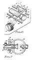
- a source 11 of compressed air may take any convenient form such as a small tank which the workman may wear on a belt or shoulder harness.
- the source 11 of compressed air may be coupled to the spray device 10 by a hose 9 in the conventional fashion, preferably at a quick connect 8 integrated with a manually actuable valve 15.
- a discharge nozzle 16 extends from an entry end within the cap assembly 13 to a discharge end outside the cap and situated diametrically opposite the air inlet.
- a control adjusting knob 17 is employed to adjust the spray mixture as will be described more fully below.
- a removable cover 7 permits charging the reservoir 12 with a load of texturizing material, and one convenient securing arrangement for removably affixing the cover 7 to the reservoir 12 is by the use of bayonet slots 6 in opposing positions on the cover 7 in co-operation with appropriately positioned outwardly directed pins 5 fixed to the walls of the reservoir 12.
- Figures 2 and 4 illustrate the extreme position of the adjustment structure in which the highest concentration of texturing material is entrained into the air stream whereas Figures 3 and 5 illustrate the extreme position of the adjustment structure in which the lowest concentration of texturing material is entrained.
- Figure 6 the manner in which the adjustment structure may be set to these two extreme positions and all intermediate positions will now be discussed.
- control adjustment knob 17 causes axle 24 to turn and an arm 19 (which has its inboard end fixed to the axle) to pivot through an identical arc represented by double-ended arrow C in Figure 6.
- a link 20 is pivotally connected at a first end to the outboard end of arm 19 and at a second end to slide member 21 which is fixed to discharge nozzle 16 near its inlet and supports the discharge nozzle in that region.
- slide member 21 is, in turn, slideably supported by elongated guides 22 positioned generally parallel to and offset from the axis formed by the air nozzle 18 and the discharge nozzle 16.
- the discharge nozzle may be moved longitudinally between its extreme axial positions (as represented by the double-ended arrow D in Figure 6) to change the area available for the texturizer to enter the air stream and accordingly change the concentration of texturizer material in the spray delivered from the discharge nozzle.
- the cap 25 includes a thickened wall region 26 through which an internally threaded aperture extends.
- the discharge nozzle 27 includes an externally threaded portion 28 which may be selectively threaded into the thickened wall region 26.
- the position of the inlet to the discharge nozzle 27 with respect to the air nozzle 29 may as readily be adjusted to suit the workman by turning the discharge nozzle, as by using an integral knurled knob 30, to establish the desired spray characteristics.
- the discharge nozzle is then locked into this selected longitudinal position by screwing a lock nut 31 against the outer surface of the thickened wall region 26 of the cap 25, the locknut being threaded onto the portion 28 intermediate the knurled knob 30 and the cap.
- the texturizing material is sprayed from the discharge nozzle in a characteristic pattern.
- Pattern refers to the cross-sectional shape of the spray and the cross-sectional measurement at any given distance from the nozzle.
- the pattern is controlled by the cross-sectional shape and dimension of the discharge nozzle.
- the tubular discharge nozzles described in connection with the foregoing embodiments of the invention emit a pattern that is round and of substantial cross-sectional dimension. Contemplated by the invention are means for selectively varying the pattern.
- a tip having internally threaded bore and end wall can be detachably securable to tubular discharge nozzle by virtue of engagement between the threaded bore and a threaded terminal portion of the discharge nozzle; a discharge orifice can extend through the end wall.
- the pattern of spray corresponds to the configuration of orifice. For example, an orifice which is circular in cross-section emits a spray which is circular in cross-section. Similarly, an orifice that is ovate in cross-section will emit a pattern that is ovate in cross-section.
- the cross-sectional dimension of the pattern is directly proportional to the cross-sectional dimension of the orifice.
- a plurality of tips each having an orifice of predetermined configuration may be made available for convenient use of the workman.
- FIG. 8 For simplicity of illustration there is seen a cap 35 a having an integrally formed discharge nozzle 50 having externally threaded terminal portion 52. Valve 15 terminating with air nozzle 18 and carried by cap 35a as previously described, is diametrically opposed to discharge nozzle 50.
- the attachment includes an elongate outer tube 53 coaxially receivable through nozzle 50 and including outboard end 54 and inboard end 55.
- Outboard end 54 functions as the discharge end.
- Inboard end 55 which is closed, is directed toward air nozzle 18.
- Tip 57 affixed to tube 53 proximate outboard end 54 includes internally threaded bore 58 which is concentric with tube 53 and removably engageable with the terminal portion 52 of nozzle 50.
- a pair of diametrically opposed apertures 59 extend through tube 53 to reside within cap 35.
- Inner tube 68, coaxially residing within the outer tube 53 extends between a discharge end 62 and inlet end 63.
- Discharge end 62 is spaced inboard of the outboard end 54 of outer tube 53.
- Inlet end 56 projects beyond the inboard end 55 of inner tube 53.
- Intermediate the ends, inner tube 68 passes through inboard end 55.
- Tube 68 is affixed to end 55 by any convenient well known means such as cri
- Inlet end 63 of inner tube 68 functions to receive pressurized air from the respective source.
- inlet end 63 is flared to mate with the frustoconical air nozzle.
- openings 59 are sized in proportion to the flow rate of the non-viscous material. Air passing through inner tube 68 draws the material into outer tube 58 through openings 59. The air and the material are mixed within outer tube 53 intermediate the end 54 thereof and the end 62 of inner tube 68 to be sprayed in a manner analogous to that provided by a conventional spray painting apparatus.
Landscapes
- Engineering & Computer Science (AREA)
- Architecture (AREA)
- Civil Engineering (AREA)
- Structural Engineering (AREA)
- Nozzles (AREA)
- Catching Or Destruction (AREA)
Claims (6)
- Spritzvorrichtung mit:(a) einem Reservoir (12) zum Aufnehmen einer Materialmenge;(b) einer Kappe (13; 35a), die an dem Boden des Reservoirs befestigt ist und deren Innenraum direkt mit dem Innenraum des Reservoirs kommuniziert, so daß Material durch Schwerkraft in den Innenraum der Kappe fließen kann;(c) einer Abgabedüse (16; 27; 50) zum Abgeben eines relativ viskosen Texturiermaterials, wobei diese Abgabedüse ein innerhalb der Kappe gelegenes Einlaßende, ein aus dieser Kappe herausragendes Abgabeende und eine zwischen dem Einlaßende und dem Abgabeende sich erstreckende Bohrung aufweist; und(d) einer Luftdüse (18) zum Abgeben von Druckluft in die Kappe, wobei diese Luftdüse (18) koaxial mit dem Einlaßende der Abgabedüse (16; 27; 50) ausgerichtet ist, und(e) einem in der Kappe (13; 35a) auswechselbar angeordneten Adapter, die Vorrichtung aus einer ersten zum Spritzen des Texturiermaterials geeigneten Konfiguration in eine zweite, zum Spritzen von relativ nicht-viskosem Material geeignete Konfiguration umzuwandeln, wobei dieser Adapter umfaßt:i) ein äußeres Rohr (53), das koaxial in der Bohrung der Abgabedüse (16; 27; 50) aufgenommen ist, und
ein Abgabeende (54),
ein gegen die Luftdüse (18) gerichtetes inneres Ende (55) und
zumindest eine Öffnung (59) aufweist, die zwischen dem Abgabeende (54) und dem inneren Ende (55) gelegen ist und durch die Material aus dem Reservoir (12) einfließen kann;ii) ein inneres Rohr (68), das in dem äußeren Rohr (53) koaxial gehalten ist und
ein Abgabeende (62), das zwischen der zumindest einen Öffnung (59) und dem Abgabeende (54) des äußeren Rohres (53) gelegen ist, und
ein Einlaßende (63) zur Aufnahme von Druckluft aus der genannten Düse (18) aufweist; undiii) eine Befestigungseinrichtung (57), um das äußere Rohr (53) an der Abgabedüse (16; 27; 50) abnehmbar zu befestigen. - Vorrichtung nach Anspruch 1, wobei das innere Ende (55) des äußeren Rohres (53) geschlossenn ist und das innere Rohr (68) durch dieses geschlossene innere Ende (55) ragt
- Vorrichtung nach Anspruch 1 oder 2, wobei die zumindest eine Öffnung (59) ein Paar Öffnungen (59) aufweist, die an gegenüberliegenden Seiten des äußeren Rohres (53) gelegen sind.
- Adapter zum auswechselbaren Einsetzen in eine Spritzvorrichtung mit:
einem Reservoir (12) zum Aufnehmen einer Menge eines Materials mit einer Kappe (13; 35a), die auswechselbar mit dem Boden des Reservoirs verbunden ist;
einer Abgabedüse (16; 27; 50) zum Abgeben eines relativ viskosen Materials, wobei die Abgabedüse nahe dem Boden des Reservoirs befestigt und ein Einlaßende innerhalb der Kappe, ein aus der Kappe herausragendes Abgabeende und eine zwischen dem Einlaßende und dem Abgabeende sich erstreckende Bohrung aufweist; und
einer Luftdüse (18) innerhalb der Kappe zum Abgeben von Druckluft, wobei diese Luftdüse koaxial mit dem Einlaßende der Abgabedüse ausgerichtet ist,
wobei der Adapter so konstruiert und angeordnet ist, um die Vorrichtung aus einer ersten zum Spritzen eines relativ viskosen Materials geeigneten Konfiguration in eine zweite zum Spritzen eines relativ nicht-viskosen Materials geeignete Konfiguration umzuwandeln,
wobei der Adapter aufweist:(a) ein äußeres Rohr (53), das innerhalb der Bohrung der Abgabedüse (16; 27; 50) koaxial aufgenommen ist undi) ein Abgabeende (54),ii) ein inneres, gegen die Luftdüse (18) gerichtetes Ende (55) undiii) zumindest eine Öffnung (59) aufweist, die zwischen dem Abgabeende (54) und dem inneren Ende (55) gelegen ist und durch die Material aus dem Reservoir (12) einfließen kann;(b) ein inneres Rohr (68), das koaxial in dem äußeren Rohr (53) gehalten ist undi) ein Abgabeende (62) zwischen der zumindest einen Öffnung (59) und dem Abgabeende (54) des äußeren Rohres (53) undii) ein Einlaßende (63) zum Aufnehmen von Druckluft aus der Düse (18) aufweist; und(c) eine Befestigungseinrichtung (57), um das äußere Rohr (53) mit der Abgabedüse (16; 27, 50) abnehmbar zu verbinden. - Adapter nach Anspruch 4, wobei das innere Ende (55) des äußeren Rohres (53) geschlossen ist und das innere Rohr (68) durch dieses geschlossene innere Ende (55) hindurchragt.
- Vorrichtung nach Anspruch 4 oder 5, wobei die zumindest eine Öffnung (59) ein Paar Öffnungen (59) aufweist, die auf gegenüberliegenden Seiten des äußeren Rohres (53) gelegen sind.
Priority Applications (1)
| Application Number | Priority Date | Filing Date | Title |
|---|---|---|---|
| AT90305809T ATE100888T1 (de) | 1989-06-02 | 1990-05-29 | Tragbares spritzgeraet. |
Applications Claiming Priority (2)
| Application Number | Priority Date | Filing Date | Title |
|---|---|---|---|
| US360776 | 1989-06-02 | ||
| US07/360,776 US5039017A (en) | 1989-06-02 | 1989-06-02 | Portable texturing machine |
Publications (2)
| Publication Number | Publication Date |
|---|---|
| EP0400957A1 EP0400957A1 (de) | 1990-12-05 |
| EP0400957B1 true EP0400957B1 (de) | 1994-01-26 |
Family
ID=23419363
Family Applications (1)
| Application Number | Title | Priority Date | Filing Date |
|---|---|---|---|
| EP90305809A Expired - Lifetime EP0400957B1 (de) | 1989-06-02 | 1990-05-29 | Tragbares Spritzgerät |
Country Status (6)
| Country | Link |
|---|---|
| US (1) | US5039017A (de) |
| EP (1) | EP0400957B1 (de) |
| JP (1) | JPH0313661A (de) |
| AT (1) | ATE100888T1 (de) |
| CA (1) | CA2015965A1 (de) |
| DE (1) | DE69006262T2 (de) |
Families Citing this family (22)
| Publication number | Priority date | Publication date | Assignee | Title |
|---|---|---|---|---|
| US5188295A (en) * | 1989-03-10 | 1993-02-23 | Djs & T Limited Partnership | Manually adjustable spray applicator |
| US5205067A (en) * | 1990-06-18 | 1993-04-27 | Thomas Matthew J | Device and method for treating mausoleums against phorid fly infestation |
| FR2679579B1 (fr) * | 1991-07-26 | 1993-11-05 | Nicolas Vitale | Appareil universel pneumatique pour crepir, jointoyer et mouchetis. |
| US6082934A (en) * | 1998-01-09 | 2000-07-04 | Pathfinder Systems, Inc. | Portable pneumatic precision metering device |
| DE29909950U1 (de) * | 1999-06-08 | 1999-09-23 | Chang, Jen-Chih, Taichung | Spritzpistolenbehälter |
| FR2840046B1 (fr) * | 2002-05-24 | 2004-07-16 | Herve Simoens | Dispositif de decharge brusque d'air avec conduite d'ejection amelioree |
| US7207497B2 (en) * | 2003-02-22 | 2007-04-24 | Clark Rikk A | Dry flake sprayer and method |
| US7500621B2 (en) | 2003-04-10 | 2009-03-10 | Homax Products, Inc. | Systems and methods for securing aerosol systems |
| US7677420B1 (en) | 2004-07-02 | 2010-03-16 | Homax Products, Inc. | Aerosol spray texture apparatus for a particulate containing material |
| US7487893B1 (en) | 2004-10-08 | 2009-02-10 | Homax Products, Inc. | Aerosol systems and methods for dispensing texture material |
| DE102005016100B3 (de) * | 2005-04-08 | 2006-10-26 | Altana Pharma Ag | Vorrichtung zur Dosierung und Trockenvernebelung |
| US8196571B2 (en) * | 2006-03-10 | 2012-06-12 | Jenson Martin W | Apparatus, system, and method for launching a granular substance |
| US7731104B2 (en) * | 2006-04-26 | 2010-06-08 | Wagner Spray Tech Corporation | Texture sprayer |
| US8469292B1 (en) | 2007-04-04 | 2013-06-25 | Homax Products, Inc. | Spray texture material compositions and dispensing systems and methods |
| US20090071734A1 (en) * | 2007-05-01 | 2009-03-19 | Hurkett Earl R | Method and Apparatus for Generating Electrical Power with Compressed Air and Vehicle Incorporating the Same |
| USD623267S1 (en) * | 2009-10-30 | 2010-09-07 | Wagner Spray Tech Corporation | Texture sprayer |
| US8840038B2 (en) | 2010-04-22 | 2014-09-23 | Ez-Pro Texture Inc. | Texturing a wall or ceiling with non-acoustical joint compound |
| DE102011008316A1 (de) * | 2010-09-10 | 2012-03-15 | Martin Ruda | Spritzpistolenbecher mit einem Farbbecher |
| US9248457B2 (en) | 2011-07-29 | 2016-02-02 | Homax Products, Inc. | Systems and methods for dispensing texture material using dual flow adjustment |
| US9156042B2 (en) | 2011-07-29 | 2015-10-13 | Homax Products, Inc. | Systems and methods for dispensing texture material using dual flow adjustment |
| USD787326S1 (en) | 2014-12-09 | 2017-05-23 | Ppg Architectural Finishes, Inc. | Cap with actuator |
| US10000672B1 (en) | 2015-12-08 | 2018-06-19 | Bevin Gordon | Spray can with pre-mixed fiberglass and resin |
Family Cites Families (22)
| Publication number | Priority date | Publication date | Assignee | Title |
|---|---|---|---|---|
| US1331465A (en) * | 1919-02-03 | 1920-02-17 | Barrett William Henry | Automatic brush |
| DE489541C (de) * | 1927-01-09 | 1930-01-20 | Zypen & Charlier G M B H V D | Abfluss-Reguliervorrichtung an Behaeltern, insbesondere an solchen fuer Staub oder aehnliches Foerdergut |
| US1730195A (en) * | 1928-06-29 | 1929-10-01 | Sterling F Thompson | Sand-blast device |
| US1835603A (en) * | 1928-07-16 | 1931-12-08 | Jr Albert E Kincaid | Ejector |
| US1892260A (en) * | 1931-01-17 | 1932-12-27 | Frank J Gainelli | Pneumatic dash gun |
| US2101922A (en) * | 1935-02-19 | 1937-12-14 | Stoesling Ludwig | Spraying apparatus |
| US2305269A (en) * | 1941-06-07 | 1942-12-15 | Moreland William | Spraying device |
| DE894761C (de) * | 1950-07-08 | 1953-10-26 | Eduard Burbach | Spritzgeraet fuer fertig angemachten Moertel |
| GB731228A (en) * | 1952-09-08 | 1955-06-01 | Giovanni Orecchia | Improvements in and relating to spraying devices |
| US2982582A (en) * | 1956-10-12 | 1961-05-02 | Alco Valve Co | Slurry feed device |
| US2887274A (en) * | 1958-02-20 | 1959-05-19 | Swan V Swenson | Spray gun for applying plaster and the like |
| US3062415A (en) * | 1959-01-14 | 1962-11-06 | John W Anderson | Improved dispenser delivering chamber |
| US3180578A (en) * | 1963-04-22 | 1965-04-27 | Elmore W Hagadorn | Spraying apparatus having cap, nipple and sleeve construction |
| US3236459A (en) * | 1963-12-16 | 1966-02-22 | Thomas P Mcritchie | Apparatus for spraying materials |
| DE1255572B (de) * | 1965-04-17 | 1967-11-30 | Siemens Ag | Einrichtung zum Ansaugen von Pulver nach dem Strahlpumpenprinzip |
| US3892607A (en) * | 1967-04-28 | 1975-07-01 | Philips Corp | Method of manufacturing semiconductor devices |
| US3708124A (en) * | 1968-06-07 | 1973-01-02 | P Kellert | Cement spray gun |
| US3690563A (en) * | 1971-01-18 | 1972-09-12 | Johnson & Johnson | Aspirator assembly |
| FR2336186A1 (fr) * | 1975-12-23 | 1977-07-22 | Jardin Ste Nle Ets | Appareil pour la projection de produits pateux |
| US4502640A (en) * | 1982-09-08 | 1985-03-05 | Italo Nonis | Multi-purpose spray gun |
| US4561808A (en) * | 1984-06-04 | 1985-12-31 | Metco Inc. | Powder feed pickup device for thermal spray guns |
| US4863104A (en) * | 1988-08-24 | 1989-09-05 | Wallboard Tool Company, Inc. | Spray gun apparatus |
-
1989
- 1989-06-02 US US07/360,776 patent/US5039017A/en not_active Expired - Lifetime
-
1990
- 1990-05-02 CA CA002015965A patent/CA2015965A1/en not_active Abandoned
- 1990-05-21 JP JP2132410A patent/JPH0313661A/ja active Pending
- 1990-05-29 DE DE69006262T patent/DE69006262T2/de not_active Expired - Fee Related
- 1990-05-29 AT AT90305809T patent/ATE100888T1/de not_active IP Right Cessation
- 1990-05-29 EP EP90305809A patent/EP0400957B1/de not_active Expired - Lifetime
Also Published As
| Publication number | Publication date |
|---|---|
| DE69006262D1 (de) | 1994-03-10 |
| US5039017A (en) | 1991-08-13 |
| JPH0313661A (ja) | 1991-01-22 |
| ATE100888T1 (de) | 1994-02-15 |
| CA2015965A1 (en) | 1990-12-02 |
| EP0400957A1 (de) | 1990-12-05 |
| DE69006262T2 (de) | 1994-09-08 |
Similar Documents
| Publication | Publication Date | Title |
|---|---|---|
| EP0400957B1 (de) | Tragbares Spritzgerät | |
| US5979797A (en) | Handheld pressurized hopper gun and method | |
| US7861950B2 (en) | Texture sprayer noise reducer | |
| US3945571A (en) | Self-contained portable pressure apparatus and hand gun assembly | |
| US9889456B2 (en) | Drywall texture application device | |
| US6450422B1 (en) | Spray gun | |
| US5443211A (en) | Spray machine for giving a texture to drywall | |
| US5186392A (en) | Liquid-applying device for cleaning wall and ceiling surfaces | |
| US6095435A (en) | Applicator systems and methods for stucco materials | |
| US4323196A (en) | Paint spraying apparatus | |
| GB1604366A (en) | Spray gun nozzle attachment | |
| WO2009075902A1 (en) | Portable texture-spraying apparatus for uniformly dispersing a viscous material | |
| US4076175A (en) | Adjustable industrial paint sprayer | |
| US20110272487A1 (en) | Portable texture-spraying apparatus for uniformly dispersing a viscous material | |
| WO2020020996A1 (en) | Spray gun for plaster material | |
| US4744519A (en) | Extension holder device for paint spraying apparatus | |
| US6283340B1 (en) | Telescopic nozzle for an air gun with safe pressure release | |
| US5797546A (en) | Weight-supported adjustable mixing and dispensing gun for two chemically reactive materials | |
| SE462584B (sv) | Anordning foer reglering av luftutmatningen i en sprutpistol | |
| SU1641449A1 (ru) | Пистолет-распылитель | |
| US3779465A (en) | Splatter pattern control for spray guns | |
| RU2085300C1 (ru) | Пистолет-распылитель | |
| RU197987U1 (ru) | Универсальный строительный пистолет | |
| EP0254564A2 (de) | Sprühpistole | |
| US5829905A (en) | Travel limiter for a dynamically pivoting multiple roller-brush spray |
Legal Events
| Date | Code | Title | Description |
|---|---|---|---|
| PUAI | Public reference made under article 153(3) epc to a published international application that has entered the european phase |
Free format text: ORIGINAL CODE: 0009012 |
|
| AK | Designated contracting states |
Kind code of ref document: A1 Designated state(s): AT BE CH DE DK ES FR GB GR IT LI LU NL SE |
|
| 17P | Request for examination filed |
Effective date: 19910604 |
|
| 17Q | First examination report despatched |
Effective date: 19911206 |
|
| GRAA | (expected) grant |
Free format text: ORIGINAL CODE: 0009210 |
|
| AK | Designated contracting states |
Kind code of ref document: B1 Designated state(s): AT BE CH DE DK ES FR GB GR IT LI LU NL SE |
|
| PG25 | Lapsed in a contracting state [announced via postgrant information from national office to epo] |
Ref country code: IT Free format text: LAPSE BECAUSE OF FAILURE TO SUBMIT A TRANSLATION OF THE DESCRIPTION OR TO PAY THE FEE WITHIN THE PRE;WARNING: LAPSES OF ITALIAN PATENTS WITH EFFECTIVE DATE BEFORE 2007 MAY HAVE OCCURRED AT ANY TIME BEFORE 2007. THE CORRECT EFFECTIVE DATE MAY BE DIFFERENT FROM THE ONE RECORDED.SCRIBED TIME-LIMIT Effective date: 19940126 Ref country code: NL Effective date: 19940126 Ref country code: BE Effective date: 19940126 Ref country code: SE Effective date: 19940126 Ref country code: LI Effective date: 19940126 Ref country code: DK Effective date: 19940126 Ref country code: AT Effective date: 19940126 Ref country code: ES Free format text: THE PATENT HAS BEEN ANNULLED BY A DECISION OF A NATIONAL AUTHORITY Effective date: 19940126 Ref country code: GR Free format text: LAPSE BECAUSE OF FAILURE TO SUBMIT A TRANSLATION OF THE DESCRIPTION OR TO PAY THE FEE WITHIN THE PRESCRIBED TIME-LIMIT Effective date: 19940126 Ref country code: FR Effective date: 19940126 Ref country code: CH Effective date: 19940126 |
|
| REF | Corresponds to: |
Ref document number: 100888 Country of ref document: AT Date of ref document: 19940215 Kind code of ref document: T |
|
| REF | Corresponds to: |
Ref document number: 69006262 Country of ref document: DE Date of ref document: 19940310 |
|
| REG | Reference to a national code |
Ref country code: CH Ref legal event code: PL |
|
| PGFP | Annual fee paid to national office [announced via postgrant information from national office to epo] |
Ref country code: GB Payment date: 19940519 Year of fee payment: 5 |
|
| PG25 | Lapsed in a contracting state [announced via postgrant information from national office to epo] |
Ref country code: LU Free format text: LAPSE BECAUSE OF NON-PAYMENT OF DUE FEES Effective date: 19940531 |
|
| EN | Fr: translation not filed | ||
| NLV1 | Nl: lapsed or annulled due to failure to fulfill the requirements of art. 29p and 29m of the patents act | ||
| PLBE | No opposition filed within time limit |
Free format text: ORIGINAL CODE: 0009261 |
|
| STAA | Information on the status of an ep patent application or granted ep patent |
Free format text: STATUS: NO OPPOSITION FILED WITHIN TIME LIMIT |
|
| 26N | No opposition filed | ||
| PG25 | Lapsed in a contracting state [announced via postgrant information from national office to epo] |
Ref country code: GB Effective date: 19950529 |
|
| GBPC | Gb: european patent ceased through non-payment of renewal fee |
Effective date: 19950529 |
|
| PGFP | Annual fee paid to national office [announced via postgrant information from national office to epo] |
Ref country code: DE Payment date: 19960524 Year of fee payment: 7 |
|
| PG25 | Lapsed in a contracting state [announced via postgrant information from national office to epo] |
Ref country code: DE Free format text: LAPSE BECAUSE OF NON-PAYMENT OF DUE FEES Effective date: 19980203 |