EP0400981A2 - Null-Strömungssensor - Google Patents
Null-Strömungssensor Download PDFInfo
- Publication number
- EP0400981A2 EP0400981A2 EP90305864A EP90305864A EP0400981A2 EP 0400981 A2 EP0400981 A2 EP 0400981A2 EP 90305864 A EP90305864 A EP 90305864A EP 90305864 A EP90305864 A EP 90305864A EP 0400981 A2 EP0400981 A2 EP 0400981A2
- Authority
- EP
- European Patent Office
- Prior art keywords
- sensing device
- flow sensing
- flow
- fluid
- force
- Prior art date
- Legal status (The legal status is an assumption and is not a legal conclusion. Google has not performed a legal analysis and makes no representation as to the accuracy of the status listed.)
- Granted
Links
Images


Classifications
-
- G—PHYSICS
- G01—MEASURING; TESTING
- G01F—MEASURING VOLUME, VOLUME FLOW, MASS FLOW OR LIQUID LEVEL; METERING BY VOLUME
- G01F1/00—Measuring the volume flow or mass flow of fluid or fluent solid material wherein the fluid passes through a meter in a continuous flow
- G01F1/05—Measuring the volume flow or mass flow of fluid or fluent solid material wherein the fluid passes through a meter in a continuous flow by using mechanical effects
- G01F1/20—Measuring the volume flow or mass flow of fluid or fluent solid material wherein the fluid passes through a meter in a continuous flow by using mechanical effects by detection of dynamic effects of the flow
- G01F1/28—Measuring the volume flow or mass flow of fluid or fluent solid material wherein the fluid passes through a meter in a continuous flow by using mechanical effects by detection of dynamic effects of the flow by drag-force, e.g. vane type or impact flowmeter
Definitions
- the present invention relates to a device for measuring fluid flow and to a circuit for operating such a device.
- a micromachined device is one which is constructed from some other part of the same device, and forms an integral part of it.
- a flow sensing device comprising a substrate of semiconductor material and a micromachined beam, the device having first and second major surfaces, the first surface further defining a pivot about which the beam is able to twist under the action of fluid flow.
- the device is constructed so that there is a channel below one half of the beam which extends throughout the substrate, and there is a cavity below the other half of the beam, such that during operation fluid may flow through the channel thus exerting a force on one half of the beam and fluid fills the cavity thus creating a differential force across the beam.
- the device thus operates on a "null" principle in that a force is applied to the beam in order to compensate for the differential force caused by the effect of fluid flow upon the beam, this compensating force being indicative of the fluid flow rate.
- the device is fabricated in a fully planar fashion and thus, unlike many prior art devices, negates the need for a second substrate to be added to the original substrate sandwiching the sensing beam between the two substrates.
- Figure 1 shows a flow sensor in accordance with the present invention comprising a beam 1 fabricated from a thin insulating film 2 typically 0.5 micrometres thick, this film 2 is coated with a metal 3 which is typically 3 micrometres thick. This metal 3 ensures that the beam 1 is both rigid and flat.
- the beam 1 is pivoted, in this example, about its mid-point by supports 4 constructed from, and integral with, the same insulating layer as the beam.
- the beam is able to pivot about the axis X-X, and the pivot supports 4 are thin, typically 0.5 micrometres, so as not to affect the sensitivity of the device at low flow rates.
- the beam is supported above a semiconductor substrate 31.
- Electrical contacts 11A, 11B are formed on the free ends of the beam, these act as one electrode of a capacitor.
- the other capacitor electrodes 6 are fabricated directly below these.
- a channel 7 is formed which extends through the semiconductor substrate 31 from the first major surface of the substrate 9 on which the beam 1 is fabricated, to the opposite major surface 10 of the substrate.
- a cavity 8 is formed below the other half of the beam 1. This cavity extends only part way through the substrate 31 and does not allow the passage of fluid through it. This then allows the device to operate on a "null" principle. This means that when the device is put in the path of a flowing fluid, because only one "through” channel exists, there will be a differential force across the beam and only the side of the beam above this "through” channel will experience this force.
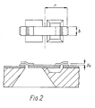
- This equilibrium position is defined as being when the contact gap at zero fluid flow (Yo in Figure 2) is equal on both sides of the beam, i.e. between 11A and 6 and 11B and 8.
- the amount of electrostatic force required and the contacts to which it is applied is determined by comparing the capacitance between the contacts 11A, 6 on one end of the beam to those on the other end of the beam 11B, 8. In this way changes in dielectric constant of the fluid do not affect the measurement of fluid flow.
- the upper limit of the range of fluid flow rates over which the device is capable of working is limited only by the amount of voltage available to apply sufficient electrostatic force.
- the fluid velocity may be obtained by utilizing the equation of motion of the overall system and standard feedback control theory.
- the deflection of the beam is small and the restoring force of the hinges is small compared to the force due to the fluid flow.
- FIG. 3 A functional block diagram of one suitable circuit for operating such a device is shown in Fig. 3.
- a sine wave voltage V o is applied across the contacts 11A and 11b.
- Amplifiers 12A and 12B convert the capacitances between these contacts into a voltage given by:- where C1 and C2 are the capacitances between the electrical contacts of the beam 11A, 11B and the electrodes 6 respectively.
- C F is the feedback capacitance around the amplifiers 12A and 12B.
- the output from the difference amplifier is of positive or negative sign depending upon whether capacitance C1 or C2 is the greater.
- the switch 17 is designed to apply the amplified error voltage from 16 to the contacts with the smallest capacitance, the resulting electrostatic force bringing the beam back to its equilibrium position.
- the square root function performed by 18A and 18B is an important addition to this circuit as it ensures the equation of motion for the overall system (including the flow sensor) is in the form of a linear differential equation, and hence is readily analysed using standard feedback control theory.
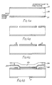
- FIGS. 4A to 4D illustrate a preferred method of fabrication of the device, the method is described as follows:
Landscapes
- Physics & Mathematics (AREA)
- Fluid Mechanics (AREA)
- General Physics & Mathematics (AREA)
- Measuring Volume Flow (AREA)
- Paper (AREA)
- Polysaccharides And Polysaccharide Derivatives (AREA)
- Silicon Polymers (AREA)
- Indicating Or Recording The Presence, Absence, Or Direction Of Movement (AREA)
- Micromachines (AREA)
- Investigating Or Analyzing Materials By The Use Of Ultrasonic Waves (AREA)
- Apparatus Associated With Microorganisms And Enzymes (AREA)
Priority Applications (1)
| Application Number | Priority Date | Filing Date | Title |
|---|---|---|---|
| AT90305864T ATE94638T1 (de) | 1989-06-02 | 1990-05-30 | Null-stroemungssensor. |
Applications Claiming Priority (2)
| Application Number | Priority Date | Filing Date | Title |
|---|---|---|---|
| GB8912755 | 1989-06-02 | ||
| GB898912755A GB8912755D0 (en) | 1989-06-02 | 1989-06-02 | A"null"flow sensor |
Publications (3)
| Publication Number | Publication Date |
|---|---|
| EP0400981A2 true EP0400981A2 (de) | 1990-12-05 |
| EP0400981A3 EP0400981A3 (de) | 1991-05-29 |
| EP0400981B1 EP0400981B1 (de) | 1993-09-15 |
Family
ID=10657801
Family Applications (1)
| Application Number | Title | Priority Date | Filing Date |
|---|---|---|---|
| EP90305864A Expired - Lifetime EP0400981B1 (de) | 1989-06-02 | 1990-05-30 | Null-Strömungssensor |
Country Status (9)
| Country | Link |
|---|---|
| US (1) | US5189918A (de) |
| EP (1) | EP0400981B1 (de) |
| JP (1) | JP2882664B2 (de) |
| AT (1) | ATE94638T1 (de) |
| AU (1) | AU631212B2 (de) |
| CA (1) | CA2018124A1 (de) |
| DE (1) | DE69003308T2 (de) |
| ES (1) | ES2044439T3 (de) |
| GB (1) | GB8912755D0 (de) |
Cited By (2)
| Publication number | Priority date | Publication date | Assignee | Title |
|---|---|---|---|---|
| DE10339907A1 (de) * | 2003-08-29 | 2005-03-31 | Fraunhofer-Gesellschaft zur Förderung der angewandten Forschung e.V. | Optische Messapparatur für Strömungen |
| DE10339906A1 (de) * | 2003-08-29 | 2005-03-31 | Fraunhofer-Gesellschaft zur Förderung der angewandten Forschung e.V. | Messapparatur für Strömungen |
Families Citing this family (5)
| Publication number | Priority date | Publication date | Assignee | Title |
|---|---|---|---|---|
| FR2580150B1 (fr) * | 1985-03-22 | 1987-06-12 | Pidoux Michel | Procede pour produire des polysaccharides permettant notamment de preparer une boisson sucree fermentee ou kefir sucre |
| US5895866A (en) * | 1996-01-22 | 1999-04-20 | Neukermans; Armand P. | Micromachined silicon micro-flow meter |
| SE9801766D0 (sv) | 1998-05-19 | 1998-05-19 | Siemens Elema Ab | Fluid flow meter |
| US6631648B2 (en) * | 2001-08-28 | 2003-10-14 | Wisconsin Alumni Research Foundation | Microfluidic flow sensing method and apparatus |
| US6941823B1 (en) * | 2001-11-07 | 2005-09-13 | Veeco Instruments Inc. | Apparatus and method to compensate for stress in a microcantilever |
Family Cites Families (8)
| Publication number | Priority date | Publication date | Assignee | Title |
|---|---|---|---|---|
| CH642461A5 (fr) * | 1981-07-02 | 1984-04-13 | Centre Electron Horloger | Accelerometre. |
| US4550616A (en) * | 1983-09-21 | 1985-11-05 | Honeywell Inc. | Pneumatic flow station |
| US4598585A (en) * | 1984-03-19 | 1986-07-08 | The Charles Stark Draper Laboratory, Inc. | Planar inertial sensor |
| DE3679663D1 (de) * | 1986-01-07 | 1991-07-11 | Emi Plc Thorn | Druckempfindlicher durchflusssensor. |
| JPS63252257A (ja) * | 1986-11-20 | 1988-10-19 | Aisin Seiki Co Ltd | 加速度検出装置 |
| GB8628611D0 (en) * | 1986-11-29 | 1987-03-18 | Accelerometer | Temperature sensing arrangement |
| GB8720357D0 (en) * | 1987-08-28 | 1987-10-07 | Thorn Emi Flow Measurement Ltd | Fluid metering system |
| GB8720355D0 (en) * | 1987-08-28 | 1987-10-07 | Emi Plc Thorn | Measuring fluid density |
-
1989
- 1989-06-02 GB GB898912755A patent/GB8912755D0/en active Pending
-
1990
- 1990-05-30 ES ES90305864T patent/ES2044439T3/es not_active Expired - Lifetime
- 1990-05-30 DE DE90305864T patent/DE69003308T2/de not_active Expired - Fee Related
- 1990-05-30 AT AT90305864T patent/ATE94638T1/de not_active IP Right Cessation
- 1990-05-30 EP EP90305864A patent/EP0400981B1/de not_active Expired - Lifetime
- 1990-06-01 JP JP2141714A patent/JP2882664B2/ja not_active Expired - Lifetime
- 1990-06-01 US US07/530,590 patent/US5189918A/en not_active Expired - Fee Related
- 1990-06-01 CA CA002018124A patent/CA2018124A1/en not_active Abandoned
- 1990-06-04 AU AU56244/90A patent/AU631212B2/en not_active Ceased
Cited By (4)
| Publication number | Priority date | Publication date | Assignee | Title |
|---|---|---|---|---|
| DE10339907A1 (de) * | 2003-08-29 | 2005-03-31 | Fraunhofer-Gesellschaft zur Förderung der angewandten Forschung e.V. | Optische Messapparatur für Strömungen |
| DE10339906A1 (de) * | 2003-08-29 | 2005-03-31 | Fraunhofer-Gesellschaft zur Förderung der angewandten Forschung e.V. | Messapparatur für Strömungen |
| DE10339907B4 (de) * | 2003-08-29 | 2006-09-21 | Fraunhofer-Gesellschaft zur Förderung der angewandten Forschung e.V. | Optische Messapparatur und Messverfahren für Strömungen |
| DE10339906B4 (de) * | 2003-08-29 | 2009-12-10 | Fraunhofer-Gesellschaft zur Förderung der angewandten Forschung e.V. | Messapparatur für Strömungen |
Also Published As
| Publication number | Publication date |
|---|---|
| ATE94638T1 (de) | 1993-10-15 |
| US5189918A (en) | 1993-03-02 |
| JP2882664B2 (ja) | 1999-04-12 |
| JPH0324464A (ja) | 1991-02-01 |
| AU5624490A (en) | 1990-12-06 |
| DE69003308D1 (de) | 1993-10-21 |
| EP0400981B1 (de) | 1993-09-15 |
| AU631212B2 (en) | 1992-11-19 |
| ES2044439T3 (es) | 1994-01-01 |
| CA2018124A1 (en) | 1990-12-02 |
| GB8912755D0 (en) | 1989-07-19 |
| EP0400981A3 (de) | 1991-05-29 |
| DE69003308T2 (de) | 1994-04-07 |
Similar Documents
| Publication | Publication Date | Title |
|---|---|---|
| US5447068A (en) | Digital capacitive accelerometer | |
| EP0054707B1 (de) | Vorrichtungen zum Feststellen von Beschleunigung und Verfahren zu deren Herstellung | |
| US7315161B2 (en) | Micro-electromechanical system (MEMS) based current and magnetic field sensor having capacitive sense components | |
| US5665253A (en) | Method of manufacturing single-wafer tunneling sensor | |
| US5817942A (en) | Capacitive in-plane accelerometer | |
| US4736629A (en) | Micro-miniature accelerometer | |
| US6223598B1 (en) | Suspension arrangement for semiconductor accelerometer | |
| AU599706B2 (en) | Micromechanical atomic force sensor head | |
| US5610335A (en) | Microelectromechanical lateral accelerometer | |
| US4926682A (en) | Viscosity sensor | |
| JP4000936B2 (ja) | 容量式力学量センサを有する検出装置 | |
| JPH0654327B2 (ja) | 単一方向性加速度計およびそれを製造する方法 | |
| EP0239703B1 (de) | Druckempfindlicher Durchflusssensor | |
| WO1989009477A1 (fr) | Agencement micromecanique | |
| EP0619494B1 (de) | Tunneleffekt-Beschleunigungssensor | |
| EP0400981B1 (de) | Null-Strömungssensor | |
| US5752410A (en) | Tunneling sensor with linear force rebalance and method for fabricating the same | |
| JPH0690219B2 (ja) | 機械的な力及び力作用を測定するための装置 | |
| Yeh et al. | A low-voltage bulk-silicon tunneling-based microaccelerometer | |
| US6462566B1 (en) | Sensor element | |
| US5763782A (en) | Micromechanical sensor | |
| US5911157A (en) | Tunnel effect sensor | |
| DE3742385A1 (de) | Beschleunigungsempfindliches elektronisches bauelement | |
| EP0632880B1 (de) | Mikromechanischer sensor | |
| WO1988005166A1 (en) | Turbulent shear force microsensor |
Legal Events
| Date | Code | Title | Description |
|---|---|---|---|
| PUAI | Public reference made under article 153(3) epc to a published international application that has entered the european phase |
Free format text: ORIGINAL CODE: 0009012 |
|
| AK | Designated contracting states |
Kind code of ref document: A2 Designated state(s): AT BE CH DE DK ES FR GB GR IT LI LU NL SE |
|
| PUAL | Search report despatched |
Free format text: ORIGINAL CODE: 0009013 |
|
| AK | Designated contracting states |
Kind code of ref document: A3 Designated state(s): AT BE CH DE DK ES FR GB GR IT LI LU NL SE |
|
| 17P | Request for examination filed |
Effective date: 19911125 |
|
| 17Q | First examination report despatched |
Effective date: 19921006 |
|
| GRAA | (expected) grant |
Free format text: ORIGINAL CODE: 0009210 |
|
| AK | Designated contracting states |
Kind code of ref document: B1 Designated state(s): AT BE CH DE DK ES FR GB GR IT LI LU NL SE |
|
| PG25 | Lapsed in a contracting state [announced via postgrant information from national office to epo] |
Ref country code: SE Effective date: 19930915 Ref country code: LI Effective date: 19930915 Ref country code: GR Free format text: LAPSE BECAUSE OF FAILURE TO SUBMIT A TRANSLATION OF THE DESCRIPTION OR TO PAY THE FEE WITHIN THE PRESCRIBED TIME-LIMIT Effective date: 19930915 Ref country code: DK Effective date: 19930915 Ref country code: CH Effective date: 19930915 Ref country code: BE Effective date: 19930915 Ref country code: AT Effective date: 19930915 |
|
| REF | Corresponds to: |
Ref document number: 94638 Country of ref document: AT Date of ref document: 19931015 Kind code of ref document: T |
|
| REF | Corresponds to: |
Ref document number: 69003308 Country of ref document: DE Date of ref document: 19931021 |
|
| ITF | It: translation for a ep patent filed | ||
| ET | Fr: translation filed | ||
| REG | Reference to a national code |
Ref country code: CH Ref legal event code: PL |
|
| REG | Reference to a national code |
Ref country code: ES Ref legal event code: FG2A Ref document number: 2044439 Country of ref document: ES Kind code of ref document: T3 |
|
| PG25 | Lapsed in a contracting state [announced via postgrant information from national office to epo] |
Ref country code: LU Free format text: LAPSE BECAUSE OF NON-PAYMENT OF DUE FEES Effective date: 19940531 |
|
| PLBE | No opposition filed within time limit |
Free format text: ORIGINAL CODE: 0009261 |
|
| STAA | Information on the status of an ep patent application or granted ep patent |
Free format text: STATUS: NO OPPOSITION FILED WITHIN TIME LIMIT |
|
| 26N | No opposition filed | ||
| REG | Reference to a national code |
Ref country code: GB Ref legal event code: 732E |
|
| NLS | Nl: assignments of ep-patents |
Owner name: CENTRAL RESEARCH LABORATORIES LIMITED |
|
| REG | Reference to a national code |
Ref country code: FR Ref legal event code: TP Free format text: CORRECTION |
|
| REG | Reference to a national code |
Ref country code: ES Ref legal event code: PC2A Owner name: CENTRAL RESEARCH LABORATORIES LIMITED |
|
| PGFP | Annual fee paid to national office [announced via postgrant information from national office to epo] |
Ref country code: DE Payment date: 19980724 Year of fee payment: 9 |
|
| PGFP | Annual fee paid to national office [announced via postgrant information from national office to epo] |
Ref country code: ES Payment date: 19980731 Year of fee payment: 9 |
|
| PGFP | Annual fee paid to national office [announced via postgrant information from national office to epo] |
Ref country code: GB Payment date: 19980810 Year of fee payment: 9 |
|
| PGFP | Annual fee paid to national office [announced via postgrant information from national office to epo] |
Ref country code: FR Payment date: 19980827 Year of fee payment: 9 |
|
| PG25 | Lapsed in a contracting state [announced via postgrant information from national office to epo] |
Ref country code: GB Free format text: LAPSE BECAUSE OF NON-PAYMENT OF DUE FEES Effective date: 19990530 |
|
| PG25 | Lapsed in a contracting state [announced via postgrant information from national office to epo] |
Ref country code: ES Free format text: LAPSE BECAUSE OF NON-PAYMENT OF DUE FEES Effective date: 19990531 |
|
| PGFP | Annual fee paid to national office [announced via postgrant information from national office to epo] |
Ref country code: NL Payment date: 19990531 Year of fee payment: 10 |
|
| GBPC | Gb: european patent ceased through non-payment of renewal fee |
Effective date: 19990530 |
|
| PG25 | Lapsed in a contracting state [announced via postgrant information from national office to epo] |
Ref country code: FR Free format text: LAPSE BECAUSE OF NON-PAYMENT OF DUE FEES Effective date: 20000131 |
|
| PG25 | Lapsed in a contracting state [announced via postgrant information from national office to epo] |
Ref country code: DE Free format text: LAPSE BECAUSE OF NON-PAYMENT OF DUE FEES Effective date: 20000301 |
|
| REG | Reference to a national code |
Ref country code: FR Ref legal event code: ST |
|
| PG25 | Lapsed in a contracting state [announced via postgrant information from national office to epo] |
Ref country code: NL Free format text: LAPSE BECAUSE OF NON-PAYMENT OF DUE FEES Effective date: 20001201 |
|
| NLV4 | Nl: lapsed or anulled due to non-payment of the annual fee |
Effective date: 20001201 |
|
| REG | Reference to a national code |
Ref country code: ES Ref legal event code: FD2A Effective date: 20010503 |
|
| PG25 | Lapsed in a contracting state [announced via postgrant information from national office to epo] |
Ref country code: IT Free format text: LAPSE BECAUSE OF NON-PAYMENT OF DUE FEES;WARNING: LAPSES OF ITALIAN PATENTS WITH EFFECTIVE DATE BEFORE 2007 MAY HAVE OCCURRED AT ANY TIME BEFORE 2007. THE CORRECT EFFECTIVE DATE MAY BE DIFFERENT FROM THE ONE RECORDED. Effective date: 20050530 |