EP0401033A2 - Dispositif d'électrophorèse capillaire utilisant une structure pour réaliser un contact électrique par moyen de la mobilité des ions - Google Patents
Dispositif d'électrophorèse capillaire utilisant une structure pour réaliser un contact électrique par moyen de la mobilité des ions Download PDFInfo
- Publication number
- EP0401033A2 EP0401033A2 EP90305988A EP90305988A EP0401033A2 EP 0401033 A2 EP0401033 A2 EP 0401033A2 EP 90305988 A EP90305988 A EP 90305988A EP 90305988 A EP90305988 A EP 90305988A EP 0401033 A2 EP0401033 A2 EP 0401033A2
- Authority
- EP
- European Patent Office
- Prior art keywords
- tube
- capillary tube
- electrolyte
- exit end
- sample
- Prior art date
- Legal status (The legal status is an assumption and is not a legal conclusion. Google has not performed a legal analysis and makes no representation as to the accuracy of the status listed.)
- Withdrawn
Links
Images


Classifications
-
- G—PHYSICS
- G01—MEASURING; TESTING
- G01N—INVESTIGATING OR ANALYSING MATERIALS BY DETERMINING THEIR CHEMICAL OR PHYSICAL PROPERTIES
- G01N27/00—Investigating or analysing materials by the use of electric, electrochemical, or magnetic means
- G01N27/26—Investigating or analysing materials by the use of electric, electrochemical, or magnetic means by investigating electrochemical variables; by using electrolysis or electrophoresis
- G01N27/416—Systems
- G01N27/447—Systems using electrophoresis
- G01N27/44704—Details; Accessories
- G01N27/44713—Particularly adapted electric power supply
-
- G—PHYSICS
- G01—MEASURING; TESTING
- G01N—INVESTIGATING OR ANALYSING MATERIALS BY DETERMINING THEIR CHEMICAL OR PHYSICAL PROPERTIES
- G01N27/00—Investigating or analysing materials by the use of electric, electrochemical, or magnetic means
- G01N27/26—Investigating or analysing materials by the use of electric, electrochemical, or magnetic means by investigating electrochemical variables; by using electrolysis or electrophoresis
- G01N27/416—Systems
- G01N27/447—Systems using electrophoresis
- G01N27/44704—Details; Accessories
- G01N27/44717—Arrangements for investigating the separated zones, e.g. localising zones
- G01N27/4473—Arrangements for investigating the separated zones, e.g. localising zones by electric means
Definitions
- This invention relates in general to capillary electrophoretic systems and in particular to an improved capillary tube with a structure that permits electrical contact through ionic movement and to a capillary electrophoretic system employing such a capillary tube.
- Capillary zone electrophoresis (CZE) in small capillaries has proven useful as an efficient method for the separation of solutes.
- An electric field is applied between the two ends of a capillary tube into which an electrolyte containing the solutes is introduced. The electric field causes the electrolyte to flow through the tube.
- Some solutes will have higher electrokinetic mobilities than other solutes so that the sample components are resolved into zones in the capillary tube during the flow of the electrolytes through the capillary.
- CZE is advantageous because it requires only very small sample volumes, such as the contents of a cell or cellular subcompartments. For these and other reasons, CZE has shown great promise as a separation and detection technique.
- CZE detection schemes include optical detection based on optical properties of sample components.
- Other CZE detection schemes include conductivity detection and electrochemical detection.
- conductivity detection a conductivity detector detects the change in conductance between two points as different zones move through the detection region.
- electrochemical detection electroactive sample components are detected when they alter the voltage across or the current between two points near the detector.
- a high voltage of the order of several tens of thousands of volts is applied between the two ends of a capillary tube in order to move the electrolyte and samples through the tube in a reasonable time and with reasonable resolution.
- Such high voltage used may create high electric fields at a detecting or measuring device which may introduce unacceptable noise or otherwise interfere with the measurement of such a device and which may, in the extreme, cause damage to the circuitry in the device. Therefore in order for conductivity or electrochemical detectors to function properly in an electrophoresis process, the electrolyte and sample at or near the location of detection should be either grounded or fixed at a low voltage which will not interfere with the measurements of the detectors.
- each end of the capillary is dipped into a reservoir.
- a high voltage is then applied between the two reservoirs.
- a high voltage is applied to one reservoir and the other reservoir is grounded.
- the two reservoirs each contains an electrolyte buffer.
- the reservoir connected to one of the two ends of the capillary is grounded so that conductivity and electrochemical detections may be performed near the tube at the location close to such reservoir.
- Such a conventional system is disadvantageous because any sample components collected will be diluted by the electrolyte buffer in the reservoir and the system does not permit continuous collection of sample components.
- the detector itself in conductivity or electrochemical detection cannot be placed directly in the electrolyte buffer, but must be placed at a location at least a short distance removed from the reservoir, the sample components actually detected by the detector is not grounded or fixed at a set low voltage. This may result in serious inaccuracies in the measurements.
- One aspect of the invention is directed toward a capillary tube comprising a wall surrounding an axis.
- the wall defines a first space inside the wall and a second space outside the wall.
- the wall is suitable for containing and confining an electrolytic solution in the first space.
- the tube further comprises a structure in the wall extending between the first and second spaces.
- the structure does not completely surround the axis so that the wall retains its structural integrity and so that the tube is suitable for use in electrophoresis without requiring structural support.
- the structure permits ions but substantially no electrolytic solution to flow therethrough, so that said structure permits electrical contact between the first and second spaces through ionic movement.
- the structure permits ionic movement between the first and second spaces, it is possible to ground or set the portion of the electrolyte and sample in the first space in the vicinity of the structure at ground or a low voltage.
- the electrolyte and sample are introduced into the inlet end of the tube and a voltage is applied between the electrolyte and sample at the inlet end of the tube and those in the vicinity of the structure, the electrolyte and sample will flow from the inlet end towards the outlet end of the tube.
- the electrolyte and sample at or near the structure is set at ground or a low voltage, the electrolyte and sample downstream from the structure will also be at ground or a low voltage.
- electrodes from conductivity or electrochemical detectors may be placed in the first space downstream from the structure for detecting the conductivity or electrochemical properties of the sample at ground or at low voltage.
- Another aspect of the invention is directed toward a capillary electrophoretic device employing the tube described above and the means for applying an electrical potential between the electrolyte and sample at the inlet end of the tube and the electrolyte and sample at the structure.
- Still another aspect of the invention is directed toward an electrophoretic method employing the capillary tube described above.
- An electrolyte and a sample are introduced into the tube.
- a voltage is applied between the sample and electrolyte at the inlet end of the tube and the sample and electrolyte at the structure so that the electrolyte and sample flow from the inlet end towards the outlet end.
- the effluent is then collected from the outlet end so that the sample component separated in the electrophoresis process can be isolated or collected.
- wire 28 and electrode 24 are grounded so that the electrolyte and sample in space 12c in the vicinity of structure 14 is also substantially grounded.
- a high voltage is applied by source 20 through wire 26 and electrode 22 to reservoir 16. Therefore, a high potential difference exists between the electrolyte and sample at end 12a and those in space 12c in the vicinity of structure 14. Such potential difference causes the electrolyte and sample introduced into end 12a to flow toward structure 14 and exit at end 12b.
- source 20 may apply a low voltage to reservoir 18. Such alternative arrangements are within the scope of the invention.
- detector 40 can be used to detect the sample at ground potential or a low voltage potential.
- System 10 therefore permits detector 40 to detect the sample at a low voltage or at ground so that conductivity and electrochemical detection can be accurately made by detector 40. The difficulties of other existing systems described above are thereby avoided.
- System 10 avoids any detrimental effects resulting from electrochemical reaction at the grounding electrode and the evolution of gas bubbles. Furthermore, since structure 14 permits ionic movement but substantially no flow of sample or electrolyte therethrough, the electrolyte and sample components that exit at end 12b is not diluted by any buffer electrolyte or sheath liquid used in other existing systems. System 10 also permits continuous collection of samples so that the sample components separated by the electrophoretic process will remain separate and can be individually collected as separate components.
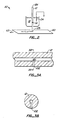
- Fig. 2 is a schematic view of a portion of an electrophoretic system 50 to illustrate another aspect of the invention.
- System 50 is similar to system 10 of Fig. 1 except that it includes in addition a surface 60, where surface 60 and end 12b move relative to each other.
- surface 60 is shown moving in direction 62 and end 12b is stationary.
- end 12b may be moved in a direction opposite to direction 62 and surface 60 kept stationary, or both surface 60 and end 12b are moved so that there is relative movement between them.
- Identical components in the different figures of this application are numbered by the same numerals for simplicity.
- access holes may be made in the side of a capillary tube by a laser drill, ion beam drill, electroerosion, chemical etching (e.g. HF etching of glass or other inorganic silicious columns or chemical etching of organic columns), where the size of the hole is suitable for accepting an electrode as well as minimal but adequate amounts of adhesive/sealant.
- chemical etching e.g. HF etching of glass or other inorganic silicious columns or chemical etching of organic columns
- Fig. 5 is the cross-sectional view of the tube portion and wire of Fig. 4, where hole 102 has been filled by a mixture 106 of fused silica and glass powder. Since end 102a of the hole 102 has been blocked by wire 104, this prevents the fused silica and glass powder mixture from entering space 12c. If the mixture is allowed to enter space 12c, the mixture may create obstructions in space 12c or totally block the flow of any fluids through space 12c.
- the composition of the frit mixture can vary considerably and still achieve the desired results.
- the proportion of Corning Solder Glass 7723 may vary from 50% to 90% by volume and the proportion of fused silica may vary from 50% to 10% by volume.
- the fused silica can also vary in size from 1 to 10 microns in diameter.
- the sintering temperature of solder glass is about 770°C and that of fused silica is about 2000°C. It has been found that satisfactory frit structures can be made by heating the mixture to about 1000°C for about 30 seconds.
- structure 14 may be constructed in a manner different from that of frit structure 106′ described above and can also be constructed using different materials such as asbestos, ceramic or metal oxide powders; such alternative constructions of structure 14 are within the scope of the invention.
- the structure 14 or 106′ in hole 102 can be made to form only a small portion of one side of the capillary tube.
- the structure does not surround the axis of the capillary tube or space 12c.
- the incorporation of the structure does not significantly affect the structural integrity of the capillary tube so that the tube can still be used in electrophoretic processes without any structural support.
- hole 102 can be completely filled, the above described structure can be made so that there is substantially no dead volume created thereby. This is in contrast to the above-described conductive joint device of Wallingford and Ewing which contains a considerable dead volume at the fracture point. This feature of the invention increases sensitivity and resolution of the electrophoretic detection and separation.
- structure 106′ is simple and reproducible.
- An electrophoretic device employing a capillary tube with a structure such as that described above can be used for electrophoretic detection and separation in a predictable and reproducible manner.
- the sample components are not diluted and the system permits continuous collection of sample components whereby the separated components remain separate.
Landscapes
- Health & Medical Sciences (AREA)
- Life Sciences & Earth Sciences (AREA)
- Molecular Biology (AREA)
- Chemical & Material Sciences (AREA)
- Chemical Kinetics & Catalysis (AREA)
- Electrochemistry (AREA)
- Physics & Mathematics (AREA)
- Analytical Chemistry (AREA)
- Biochemistry (AREA)
- General Health & Medical Sciences (AREA)
- General Physics & Mathematics (AREA)
- Immunology (AREA)
- Pathology (AREA)
- Engineering & Computer Science (AREA)
- Power Engineering (AREA)
- Investigating Or Analyzing Materials By The Use Of Electric Means (AREA)
- Investigating Or Analysing Biological Materials (AREA)
- Devices For Indicating Variable Information By Combining Individual Elements (AREA)
- Sampling And Sample Adjustment (AREA)
Applications Claiming Priority (2)
| Application Number | Priority Date | Filing Date | Title |
|---|---|---|---|
| US359512 | 1989-06-01 | ||
| US07/359,512 US4908116A (en) | 1989-06-01 | 1989-06-01 | Capillary electrophoretic device employing structure permitting electrical contact through ionic movement |
Publications (2)
| Publication Number | Publication Date |
|---|---|
| EP0401033A2 true EP0401033A2 (fr) | 1990-12-05 |
| EP0401033A3 EP0401033A3 (fr) | 1991-08-07 |
Family
ID=23414138
Family Applications (1)
| Application Number | Title | Priority Date | Filing Date |
|---|---|---|---|
| EP19900305988 Withdrawn EP0401033A3 (fr) | 1989-06-01 | 1990-06-01 | Dispositif d'électrophorèse capillaire utilisant une structure pour réaliser un contact électrique par moyen de la mobilité des ions |
Country Status (4)
| Country | Link |
|---|---|
| US (1) | US4908116A (fr) |
| EP (1) | EP0401033A3 (fr) |
| JP (1) | JP3086472B2 (fr) |
| CA (1) | CA2017515A1 (fr) |
Cited By (13)
| Publication number | Priority date | Publication date | Assignee | Title |
|---|---|---|---|---|
| EP0576361A3 (fr) * | 1992-06-26 | 1994-11-17 | Nakano Vinegar Co Ltd | Electrode électrophorétique, méthode et ou système pour l'électrophorèse capillaire utilisant l'électrode électrophorétique et collecteur de fractions installé dans le système d'électrophorèse capillaire. |
| EP0489445A3 (en) * | 1990-12-06 | 1995-04-26 | Sumitomo Electric Industries | Method and apparatus for fractionation |
| DE102010041433A1 (de) * | 2010-09-27 | 2012-03-29 | Fraunhofer-Gesellschaft zur Förderung der angewandten Forschung e.V. | Kapillarröhrchen für die Elektrophorese |
| US9216412B2 (en) | 2009-11-23 | 2015-12-22 | Cyvek, Inc. | Microfluidic devices and methods of manufacture and use |
| US9229001B2 (en) | 2009-11-23 | 2016-01-05 | Cyvek, Inc. | Method and apparatus for performing assays |
| US9500645B2 (en) | 2009-11-23 | 2016-11-22 | Cyvek, Inc. | Micro-tube particles for microfluidic assays and methods of manufacture |
| US9546932B2 (en) | 2009-11-23 | 2017-01-17 | Cyvek, Inc. | Microfluidic assay operating system and methods of use |
| US9651568B2 (en) | 2009-11-23 | 2017-05-16 | Cyvek, Inc. | Methods and systems for epi-fluorescent monitoring and scanning for microfluidic assays |
| US9700889B2 (en) | 2009-11-23 | 2017-07-11 | Cyvek, Inc. | Methods and systems for manufacture of microarray assay systems, conducting microfluidic assays, and monitoring and scanning to obtain microfluidic assay results |
| US9759718B2 (en) | 2009-11-23 | 2017-09-12 | Cyvek, Inc. | PDMS membrane-confined nucleic acid and antibody/antigen-functionalized microlength tube capture elements, and systems employing them, and methods of their use |
| US9855735B2 (en) | 2009-11-23 | 2018-01-02 | Cyvek, Inc. | Portable microfluidic assay devices and methods of manufacture and use |
| US10065403B2 (en) | 2009-11-23 | 2018-09-04 | Cyvek, Inc. | Microfluidic assay assemblies and methods of manufacture |
| US10228367B2 (en) | 2015-12-01 | 2019-03-12 | ProteinSimple | Segmented multi-use automated assay cartridge |
Families Citing this family (15)
| Publication number | Priority date | Publication date | Assignee | Title |
|---|---|---|---|---|
| USRE35102E (en) * | 1989-06-01 | 1995-11-28 | The Board Of Trustees Of The Leland Stanford Junior University | Capillary electrophoretic device employing structure permitting electrical contact through ionic movement |
| US4908116A (en) * | 1989-06-01 | 1990-03-13 | The Board Of Trustees At The Leland Stanford Junior University | Capillary electrophoretic device employing structure permitting electrical contact through ionic movement |
| US5126025A (en) * | 1990-08-30 | 1992-06-30 | Millipore Corporation | Method and apparatus for effecting capillary electrophoresis fraction collection on a membrane |
| US5298139A (en) * | 1990-09-10 | 1994-03-29 | Board Of Trustees Of The Leland Stanford Junior University | End-column conductivity detector for capillary zone electrophoresis |
| US5340452A (en) * | 1991-02-01 | 1994-08-23 | Beckman Instruments, Inc. | On-column preconcentration of samples in capillary electrophoresis |
| US5358612A (en) * | 1991-09-24 | 1994-10-25 | The Dow Chemical Company | Electrophoresis with chemically suppressed detection |
| KR970007071B1 (ko) * | 1991-09-24 | 1997-05-02 | 더 다우 케미칼 캄파니 | 화학적 억제 검출 수단을 가진 전기 영동 방법 및 장치 |
| US5169510A (en) * | 1992-03-02 | 1992-12-08 | Oread Laboratories | Ion-permeable polymer joint for use in capillary electrophoresis |
| US5505831A (en) * | 1993-01-26 | 1996-04-09 | Bio-Rad Laboratories, Inc. | Concentration of biological samples on a microliter scale and analysis by capillary electrophoresis |
| US5441613A (en) * | 1993-12-03 | 1995-08-15 | Dionex Corporation | Methods and apparatus for real-time monitoring, measurement and control of electroosmotic flow |
| US5423966A (en) * | 1994-01-25 | 1995-06-13 | Perkin-Elmer Corporation | On line ion contaminant removal apparatus and method for capillary electrophoresis |
| US5573651A (en) * | 1995-04-17 | 1996-11-12 | The Dow Chemical Company | Apparatus and method for flow injection analysis |
| US5580434A (en) * | 1996-02-29 | 1996-12-03 | Hewlett-Packard Company | Interface apparatus for capillary electrophoresis to a matrix-assisted-laser-desorption-ionization mass spectrometer |
| US6140640A (en) * | 1999-02-25 | 2000-10-31 | Water Investments Limited | Electrospray device |
| WO2004038752A2 (fr) * | 2002-10-21 | 2004-05-06 | The Government Of The United States Of America, As Represented By The Secretary, Department Of Health And Human Services | Sources d'electronebulisation a capillaires contigus et dispositif analytique |
Family Cites Families (12)
| Publication number | Priority date | Publication date | Assignee | Title |
|---|---|---|---|---|
| US2925370A (en) * | 1958-06-13 | 1960-02-16 | Beckman Instruments Inc | Electrochemical leak structure and method for producing same |
| US3282818A (en) * | 1963-03-12 | 1966-11-01 | Beckman Instruments Inc | Electrochemical liquid junction structure and method for producing same |
| US3658679A (en) * | 1969-04-14 | 1972-04-25 | Us Air Force | System for determining the hydrogen ion concentration of flowing liquids |
| US4404154A (en) * | 1979-12-07 | 1983-09-13 | Arons Richard M | Method for preparing corrosion-resistant ceramic shapes |
| JPS606910B2 (ja) * | 1981-12-09 | 1985-02-21 | 日本碍子株式会社 | 金属セラミツクス接合体 |
| EP0153737B1 (fr) * | 1984-02-27 | 1993-07-28 | Kabushiki Kaisha Toshiba | Substrat pour circuit à haute thermoconductivité |
| CH660176A5 (de) * | 1984-07-06 | 1987-03-31 | Bbc Brown Boveri & Cie | Metall-keramik-verbundelement und verfahren zu dessen herstellung. |
| FR2574311B1 (fr) * | 1984-12-11 | 1989-09-15 | Inst Nat Sante Rech Med | Perfectionnements aux procedes et appareils d'electrophorese preparative |
| KR890003856B1 (ko) * | 1985-09-10 | 1989-10-05 | 가부시끼 가이샤 도시바 | 세라믹스 소결체용 금속화 조성물 |
| EP0235682B2 (fr) * | 1986-02-20 | 1997-11-12 | Kabushiki Kaisha Toshiba | Corps frité à base de nitrure d'aluminium, muni d'une couche métallisée conductrice |
| DE3630066C1 (de) * | 1986-09-04 | 1988-02-04 | Heraeus Gmbh W C | Verfahren zur Herstellung von gesinterten metallisierten Aluminiumnitrid-Keramikkoerpern |
| US4908116A (en) * | 1989-06-01 | 1990-03-13 | The Board Of Trustees At The Leland Stanford Junior University | Capillary electrophoretic device employing structure permitting electrical contact through ionic movement |
-
1989
- 1989-06-01 US US07/359,512 patent/US4908116A/en not_active Ceased
-
1990
- 1990-05-24 CA CA002017515A patent/CA2017515A1/fr not_active Abandoned
- 1990-06-01 JP JP02144244A patent/JP3086472B2/ja not_active Expired - Fee Related
- 1990-06-01 EP EP19900305988 patent/EP0401033A3/fr not_active Withdrawn
Cited By (15)
| Publication number | Priority date | Publication date | Assignee | Title |
|---|---|---|---|---|
| EP0489445A3 (en) * | 1990-12-06 | 1995-04-26 | Sumitomo Electric Industries | Method and apparatus for fractionation |
| EP0576361A3 (fr) * | 1992-06-26 | 1994-11-17 | Nakano Vinegar Co Ltd | Electrode électrophorétique, méthode et ou système pour l'électrophorèse capillaire utilisant l'électrode électrophorétique et collecteur de fractions installé dans le système d'électrophorèse capillaire. |
| US9500645B2 (en) | 2009-11-23 | 2016-11-22 | Cyvek, Inc. | Micro-tube particles for microfluidic assays and methods of manufacture |
| US9216412B2 (en) | 2009-11-23 | 2015-12-22 | Cyvek, Inc. | Microfluidic devices and methods of manufacture and use |
| US9229001B2 (en) | 2009-11-23 | 2016-01-05 | Cyvek, Inc. | Method and apparatus for performing assays |
| US9546932B2 (en) | 2009-11-23 | 2017-01-17 | Cyvek, Inc. | Microfluidic assay operating system and methods of use |
| US9651568B2 (en) | 2009-11-23 | 2017-05-16 | Cyvek, Inc. | Methods and systems for epi-fluorescent monitoring and scanning for microfluidic assays |
| US9700889B2 (en) | 2009-11-23 | 2017-07-11 | Cyvek, Inc. | Methods and systems for manufacture of microarray assay systems, conducting microfluidic assays, and monitoring and scanning to obtain microfluidic assay results |
| US9759718B2 (en) | 2009-11-23 | 2017-09-12 | Cyvek, Inc. | PDMS membrane-confined nucleic acid and antibody/antigen-functionalized microlength tube capture elements, and systems employing them, and methods of their use |
| US9855735B2 (en) | 2009-11-23 | 2018-01-02 | Cyvek, Inc. | Portable microfluidic assay devices and methods of manufacture and use |
| US10022696B2 (en) | 2009-11-23 | 2018-07-17 | Cyvek, Inc. | Microfluidic assay systems employing micro-particles and methods of manufacture |
| US10065403B2 (en) | 2009-11-23 | 2018-09-04 | Cyvek, Inc. | Microfluidic assay assemblies and methods of manufacture |
| US9410925B2 (en) | 2010-09-27 | 2016-08-09 | Fraunhofer-Gesellschaft Zur Forderung Der Angewandten Forschung E.V. | Capillary tubes for electrophoresis |
| DE102010041433A1 (de) * | 2010-09-27 | 2012-03-29 | Fraunhofer-Gesellschaft zur Förderung der angewandten Forschung e.V. | Kapillarröhrchen für die Elektrophorese |
| US10228367B2 (en) | 2015-12-01 | 2019-03-12 | ProteinSimple | Segmented multi-use automated assay cartridge |
Also Published As
| Publication number | Publication date |
|---|---|
| JP3086472B2 (ja) | 2000-09-11 |
| JPH0329845A (ja) | 1991-02-07 |
| EP0401033A3 (fr) | 1991-08-07 |
| US4908116A (en) | 1990-03-13 |
| CA2017515A1 (fr) | 1990-12-01 |
Similar Documents
| Publication | Publication Date | Title |
|---|---|---|
| US4908116A (en) | Capillary electrophoretic device employing structure permitting electrical contact through ionic movement | |
| Ye et al. | Amperometric detection in capillary electrophoresis with normal size electrodes | |
| Wallingford et al. | Amperometric detection of catechols in capillary zone electrophoresis with normal and micellar solutions | |
| Ewing et al. | Electrochemical detection in microcolumn separations | |
| Harrison et al. | Capillary electrophoresis and sample injection systems integrated on a planar glass chip | |
| Tagliaro et al. | A brief introduction to capillary electrophoresis | |
| Yik et al. | Micellar electrokinetic capillary chromatography of vitamin B6 with electrochemical detection | |
| US5378334A (en) | System for measuring and controlling electroosmosis in separation techniques | |
| JP3011914B2 (ja) | マイクロカラムによる動電分離用のオンカラム式電導度検出器 | |
| Huang et al. | Use of an on-column frit in capillary zone electrophoresis: sample collection | |
| JPH05505463A (ja) | 増強キャピラリーゾーン電気泳動法及びそれの実施装置 | |
| EP0838029B1 (fr) | Tube capillaire d'electrophorese ayant un embout conducteur | |
| US5126023A (en) | End-column electrical and electrochemical detector for capillary zone electrophoresis | |
| Wallingford et al. | Characterization of a microinjector for capillary zone electrophoresis | |
| US5223114A (en) | On-column conductivity detector for microcolumn electrokinetic separations | |
| Nakagawa et al. | SEPARATION AND DETERMINATION OF CEFPIRANIDE IN HUMAN PLASMA BY ELECTROKINETIC CHROMATOGRAPHY WITH A MICELLAR SOLUTION AND AN OPEN TUBULAR-FUSED SILICA CAPILLARY | |
| Marina et al. | Capillary electrophoresis | |
| USRE35102E (en) | Capillary electrophoretic device employing structure permitting electrical contact through ionic movement | |
| von Heeren et al. | Characterization of electrophoretic sample injection and separation in a gel‐filled cyclic planar microstructure | |
| EP1818673B1 (fr) | Instrument électrophorétique capillaire et ensemble du réseau capillaire | |
| US5298139A (en) | End-column conductivity detector for capillary zone electrophoresis | |
| US6843901B1 (en) | Potential gradient detector for electrophoresis | |
| US6787017B1 (en) | Capillary electrophoretis system, sample analyzer and liquid sample cassette for electrophoretic separation | |
| US6190521B1 (en) | Method and apparatus for feeding a sample into a capillary electrophoresis apparatus | |
| JPH0894578A (ja) | キャピラリー電気泳動装置 |
Legal Events
| Date | Code | Title | Description |
|---|---|---|---|
| PUAI | Public reference made under article 153(3) epc to a published international application that has entered the european phase |
Free format text: ORIGINAL CODE: 0009012 |
|
| AK | Designated contracting states |
Kind code of ref document: A2 Designated state(s): CH DE FR GB IT LI SE |
|
| PUAL | Search report despatched |
Free format text: ORIGINAL CODE: 0009013 |
|
| AK | Designated contracting states |
Kind code of ref document: A3 Designated state(s): CH DE FR GB IT LI SE |
|
| 17P | Request for examination filed |
Effective date: 19910926 |
|
| 17Q | First examination report despatched |
Effective date: 19930505 |
|
| STAA | Information on the status of an ep patent application or granted ep patent |
Free format text: STATUS: THE APPLICATION IS DEEMED TO BE WITHDRAWN |
|
| 18D | Application deemed to be withdrawn |
Effective date: 19940614 |