EP0401064B1 - Laser-Dioden-gepumpter Leistungs-Laser - Google Patents
Laser-Dioden-gepumpter Leistungs-Laser Download PDFInfo
- Publication number
- EP0401064B1 EP0401064B1 EP90401212A EP90401212A EP0401064B1 EP 0401064 B1 EP0401064 B1 EP 0401064B1 EP 90401212 A EP90401212 A EP 90401212A EP 90401212 A EP90401212 A EP 90401212A EP 0401064 B1 EP0401064 B1 EP 0401064B1
- Authority
- EP
- European Patent Office
- Prior art keywords
- axis
- laser
- power laser
- diodes
- cylinder
- Prior art date
- Legal status (The legal status is an assumption and is not a legal conclusion. Google has not performed a legal analysis and makes no representation as to the accuracy of the status listed.)
- Expired - Lifetime
Links
- 230000003287 optical effect Effects 0.000 claims description 20
- 238000001069 Raman spectroscopy Methods 0.000 claims description 9
- 230000008878 coupling Effects 0.000 claims description 8
- 238000010168 coupling process Methods 0.000 claims description 8
- 238000005859 coupling reaction Methods 0.000 claims description 8
- 239000000463 material Substances 0.000 claims description 6
- 239000002184 metal Substances 0.000 claims 2
- 230000014759 maintenance of location Effects 0.000 claims 1
- 238000005086 pumping Methods 0.000 description 27
- 230000000694 effects Effects 0.000 description 10
- 230000007704 transition Effects 0.000 description 7
- 230000008901 benefit Effects 0.000 description 5
- 239000013078 crystal Substances 0.000 description 5
- 238000010521 absorption reaction Methods 0.000 description 4
- 238000006243 chemical reaction Methods 0.000 description 4
- 238000013461 design Methods 0.000 description 4
- 150000002500 ions Chemical class 0.000 description 4
- VNWKTOKETHGBQD-UHFFFAOYSA-N methane Chemical compound C VNWKTOKETHGBQD-UHFFFAOYSA-N 0.000 description 4
- 230000010287 polarization Effects 0.000 description 4
- 230000001427 coherent effect Effects 0.000 description 3
- 235000021183 entrée Nutrition 0.000 description 3
- 238000003780 insertion Methods 0.000 description 3
- 230000037431 insertion Effects 0.000 description 3
- 239000007787 solid Substances 0.000 description 3
- 230000003595 spectral effect Effects 0.000 description 3
- 238000012546 transfer Methods 0.000 description 3
- PEDCQBHIVMGVHV-UHFFFAOYSA-N Glycerine Chemical compound OCC(O)CO PEDCQBHIVMGVHV-UHFFFAOYSA-N 0.000 description 2
- 230000003667 anti-reflective effect Effects 0.000 description 2
- 238000003491 array Methods 0.000 description 2
- 239000000203 mixture Substances 0.000 description 2
- 230000003071 parasitic effect Effects 0.000 description 2
- -1 rare earth ion Chemical class 0.000 description 2
- 229910052761 rare earth metal Inorganic materials 0.000 description 2
- 230000006978 adaptation Effects 0.000 description 1
- 238000013459 approach Methods 0.000 description 1
- 230000000903 blocking effect Effects 0.000 description 1
- 239000004020 conductor Substances 0.000 description 1
- 238000001816 cooling Methods 0.000 description 1
- 230000005284 excitation Effects 0.000 description 1
- 239000000835 fiber Substances 0.000 description 1
- 230000017525 heat dissipation Effects 0.000 description 1
- 238000010438 heat treatment Methods 0.000 description 1
- 238000012423 maintenance Methods 0.000 description 1
- 238000004519 manufacturing process Methods 0.000 description 1
- 239000011159 matrix material Substances 0.000 description 1
- 238000010899 nucleation Methods 0.000 description 1
- 239000013307 optical fiber Substances 0.000 description 1
- 230000005693 optoelectronics Effects 0.000 description 1
- 244000045947 parasite Species 0.000 description 1
- 238000005498 polishing Methods 0.000 description 1
- 238000012545 processing Methods 0.000 description 1
- 238000002310 reflectometry Methods 0.000 description 1
- 238000013519 translation Methods 0.000 description 1
- 230000001960 triggered effect Effects 0.000 description 1
Images


Classifications
-
- H—ELECTRICITY
- H01—ELECTRIC ELEMENTS
- H01S—DEVICES USING THE PROCESS OF LIGHT AMPLIFICATION BY STIMULATED EMISSION OF RADIATION [LASER] TO AMPLIFY OR GENERATE LIGHT; DEVICES USING STIMULATED EMISSION OF ELECTROMAGNETIC RADIATION IN WAVE RANGES OTHER THAN OPTICAL
- H01S3/00—Lasers, i.e. devices using stimulated emission of electromagnetic radiation in the infrared, visible or ultraviolet wave range
- H01S3/09—Processes or apparatus for excitation, e.g. pumping
- H01S3/091—Processes or apparatus for excitation, e.g. pumping using optical pumping
- H01S3/094—Processes or apparatus for excitation, e.g. pumping using optical pumping by coherent light
- H01S3/0941—Processes or apparatus for excitation, e.g. pumping using optical pumping by coherent light of a laser diode
- H01S3/09415—Processes or apparatus for excitation, e.g. pumping using optical pumping by coherent light of a laser diode the pumping beam being parallel to the lasing mode of the pumped medium, e.g. end-pumping
-
- H—ELECTRICITY
- H01—ELECTRIC ELEMENTS
- H01S—DEVICES USING THE PROCESS OF LIGHT AMPLIFICATION BY STIMULATED EMISSION OF RADIATION [LASER] TO AMPLIFY OR GENERATE LIGHT; DEVICES USING STIMULATED EMISSION OF ELECTROMAGNETIC RADIATION IN WAVE RANGES OTHER THAN OPTICAL
- H01S3/00—Lasers, i.e. devices using stimulated emission of electromagnetic radiation in the infrared, visible or ultraviolet wave range
- H01S3/23—Arrangements of two or more lasers not provided for in groups H01S3/02 - H01S3/22, e.g. tandem arrangements of separate active media
- H01S3/2383—Parallel arrangements
-
- H—ELECTRICITY
- H01—ELECTRIC ELEMENTS
- H01S—DEVICES USING THE PROCESS OF LIGHT AMPLIFICATION BY STIMULATED EMISSION OF RADIATION [LASER] TO AMPLIFY OR GENERATE LIGHT; DEVICES USING STIMULATED EMISSION OF ELECTROMAGNETIC RADIATION IN WAVE RANGES OTHER THAN OPTICAL
- H01S3/00—Lasers, i.e. devices using stimulated emission of electromagnetic radiation in the infrared, visible or ultraviolet wave range
- H01S3/05—Construction or shape of optical resonators; Accommodation of active medium therein; Shape of active medium
- H01S3/08—Construction or shape of optical resonators or components thereof
- H01S3/08059—Constructional details of the reflector, e.g. shape
-
- H—ELECTRICITY
- H01—ELECTRIC ELEMENTS
- H01S—DEVICES USING THE PROCESS OF LIGHT AMPLIFICATION BY STIMULATED EMISSION OF RADIATION [LASER] TO AMPLIFY OR GENERATE LIGHT; DEVICES USING STIMULATED EMISSION OF ELECTROMAGNETIC RADIATION IN WAVE RANGES OTHER THAN OPTICAL
- H01S3/00—Lasers, i.e. devices using stimulated emission of electromagnetic radiation in the infrared, visible or ultraviolet wave range
- H01S3/09—Processes or apparatus for excitation, e.g. pumping
- H01S3/091—Processes or apparatus for excitation, e.g. pumping using optical pumping
- H01S3/094—Processes or apparatus for excitation, e.g. pumping using optical pumping by coherent light
- H01S3/09408—Pump redundancy
-
- H—ELECTRICITY
- H01—ELECTRIC ELEMENTS
- H01S—DEVICES USING THE PROCESS OF LIGHT AMPLIFICATION BY STIMULATED EMISSION OF RADIATION [LASER] TO AMPLIFY OR GENERATE LIGHT; DEVICES USING STIMULATED EMISSION OF ELECTROMAGNETIC RADIATION IN WAVE RANGES OTHER THAN OPTICAL
- H01S3/00—Lasers, i.e. devices using stimulated emission of electromagnetic radiation in the infrared, visible or ultraviolet wave range
- H01S3/10—Controlling the intensity, frequency, phase, polarisation or direction of the emitted radiation, e.g. switching, gating, modulating or demodulating
- H01S3/10084—Frequency control by seeding
- H01S3/10092—Coherent seed, e.g. injection locking
-
- H—ELECTRICITY
- H01—ELECTRIC ELEMENTS
- H01S—DEVICES USING THE PROCESS OF LIGHT AMPLIFICATION BY STIMULATED EMISSION OF RADIATION [LASER] TO AMPLIFY OR GENERATE LIGHT; DEVICES USING STIMULATED EMISSION OF ELECTROMAGNETIC RADIATION IN WAVE RANGES OTHER THAN OPTICAL
- H01S3/00—Lasers, i.e. devices using stimulated emission of electromagnetic radiation in the infrared, visible or ultraviolet wave range
- H01S3/10—Controlling the intensity, frequency, phase, polarisation or direction of the emitted radiation, e.g. switching, gating, modulating or demodulating
- H01S3/106—Controlling the intensity, frequency, phase, polarisation or direction of the emitted radiation, e.g. switching, gating, modulating or demodulating by controlling devices placed within the cavity
- H01S3/108—Controlling the intensity, frequency, phase, polarisation or direction of the emitted radiation, e.g. switching, gating, modulating or demodulating by controlling devices placed within the cavity using non-linear optical devices, e.g. exhibiting Brillouin or Raman scattering
- H01S3/109—Frequency multiplication, e.g. harmonic generation
Definitions
- the invention relates to power lasers pumped by laser diodes and in particular a set of several power lasers pumped by laser diodes.
- An alternative consists in using sheets of optical fibers which, coupled to the pumping sources, allow thermal problems to be dissociated by offset at the pumping sources.
- This basic configuration has drawbacks related to the fact that the coupling efficiency (input-output) in the fiber bundles is not 100%, and that the gain distribution will always be less well suited to the comparatively cavity mode. to that obtained by a longitudinal pumping.
- the residual thermal effects are linked to the quantum efficiency of the transfer which varies in the ratio (w1 / w p : laser transition frequency / absorption frequency (ie pump) and for example mean that if one wishes to obtain 1mJ at 1.064 ⁇ m from the transition 4F 3/2 4I 9/2 of the Nd3+ ion inserted in the YAG matrix, the pump energy at 0.808 ⁇ m must be 1.3168 mJ.
- This pump wavelength characterizes the absorption band associated with the transition between the levels 4 I 11/1 and 4F 5/2
- the ratio W1 / w p is equal to 0.7594, which also means that 0.3168 mJ participates in the heating of the medium, this energy corresponding to non-radiative transitions.
- the field covered by the present invention relates to solid state power lasers pumped by laser diodes.
- the demonstrations were mainly postponed using longitudinal pumping, which limits the power levels that can be obtained. Indeed, the length of the bar or more generally the volume effectively excited is limited by the absorption of the medium at the pump wavelength. As an example for Nd: YAG, this length is 5mm. Obtaining a higher power level then passes through a transverse pumping of a bar or a plate of radius or thickness adapted to absorb the power of the pump.
- the pumping has a resonant character, part of the absorbed power is however transformed (via the excitation of non-radiative transitions) into heat.
- the power level required to pump and produce a power laser requires the implementation of a heat removal system at the power laser diodes (remember that the conversion efficiency optical / electrical in a laser diode is typically between 40 to 50%). The problem then arises of designing a power laser head pumped by laser diodes taking these problems into account.
- the object of the present invention is based on the implementation of a new type of architecture of the pumping mode and cavity, with the aim of producing a power laser pumped by laser diodes minimizing the residual thermal effects at the level active medium. It is based on the use of longitudinal pumping by laser diodes of several laser bars.
- the invention also relates to a power laser, characterized in that the two laser diodes and the amplifying media are located symmetrically with respect to an axis (XX ') and that the optical coupling system comprises, associated with each amplifying medium of the first mirrors inclined with respect to the direction of the output beam (Fs, Fs ') of the amplifying medium and located symmetrically with respect to the axis (XX') as well as the second mirrors also situated symmetrically with respect to the 'axis (XX') receiving the output beams (Fs, Fs') reflected by the first mirrors and reflecting them substantially along the axis (XX '), said output mirror being aligned along this axis (XX').
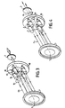
- the invention relates to a power laser, comprising a plurality of laser diodes and amplifier media arranged according to the generatrices of a fictitious cylinder of axis (XX '), and in that the optical coupling system comprises a first reflecting device comprising a conical reflecting crown having as axis the axis (XX ') of the cylinder and reflecting the output beams of the different amplifying media towards the axis (XX') of the cylinder, as well as a second reflecting device comprising conical reflecting surface arranged along the axis (XX ') of the cylinder and reflecting the exit beams along the axis (XX') of the cylinder, said exit mirror being aligned along this axis (XX ').
- a first reflecting device comprising a conical reflecting crown having as axis the axis (XX ') of the cylinder and reflecting the output beams of the different amplifying media towards the axis (XX') of the cylinder
- Each laser diode can be an association of stacked arrays or ribbons composed of a multitude of laser diodes.
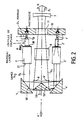
- Each laser diode emits a pump beam Fp of a determined pump wavelength which each longitudinally pumps an amplifier such as a laser rod 3.3 'via an adaptation optic 2, 2' anamorphic type.
- Each laser bar has a surface 30, 30 ′ treated mechanically (radius of curvature) and optically (multi-electric layers) so as to have a maximum reflection coefficient at the laser wavelength and a minimum reflection coefficient at the length of pump wave specific to the rare earth ion used.
- the length of each bar is adapted to the absorption coefficient, the pump wavelength and the weight doping rate.
- the length of each crystal is of the order of 5 mm.
- the other face of the bar can be treated with anti-reflective treatment at the laser wavelength or / and Brewster incidence by polishing in order to carry out a selection of state of polarization on the laser wave.
- Each beam Fs, Fs' incident on the optical system which works in reflections and makes it possible to couple each elementary system to a common output mirror 7.
- this optical system comprises reflection devices 40, 40 'reflecting the beams Fs and Fs' towards the axis XX 'and a reflection device 5 reflecting these beams in the direction of the axis XX' towards a mirror 7 which then constitutes, with the treated surfaces 30, 30 'of the bars 3, 3' an optical cavity.
- the reflection devices 40, 40' are constituted by a diopter of annular shape of axis XX 'presenting, to beams such as Fs, Fs' a conical reflecting surface.
- the reflection device 5 is a conical diopter of axis XX 'situated on this axis to receive the beams Fs, Fs' and retransmit them in the form of a beam Fc, along the axis XX', towards the mirror 7.
- the device 5 is oriented so that the beam Fc leaves the device.
- the reflection device 5 is oriented so that the beam Fc enters the device.
- the base 10 is then provided with a hole 11 allowing the beam Fc to exit the device.
- the beam Fp is oriented in the direction of the axis XX ', the beam is sent by the reflection device 5 in the opposite direction to the axis XX' which constitutes a structure in folded mode.
- a set of half-wave plates 6, 6 ′ allows the polarization state of each elementary beam to be adjusted so that all of them are in the polarization state suitable for the use of a system electro-optic for opening the cavity using the switch (Q-Switch) 8.
- the configuration of the structure of FIG. 2 makes it possible to modify the length of cavity by translation of the optical assembly 4, 4 ′, 5. This makes it possible to adjust the width of laser pulses generated from an operation in "Q-Switch" mode. In this case, the lifetime of the photon in the cavity is modified.
- the realization of a power laser involves the insertion of a cavity blocking system in order to obtain a strong population inversion.
- the electro-optical effect makes it possible to control the opening of the cavity and thus to obtain a very high stimulated emission.
- the conditions on the state of polarization of the beams require the use of half-wave plates as has been mentioned previously and d '' a common modulator which can be positioned in place of the Q-Switch 8.
- each elementary laser can be controlled individually by inserting an electrooptical modulator not shown on each channel.
- the phasing of the various lasers can be carried out on the basis of a reflection on the output mirror 7 or on a parasitic reflection on the electrooptical modulator (although the latter is anti-reflective).
- FIGS 3 and 4 show devices according to the invention in which there is provided a control beam FA used for control for phasing.
- the device of FIG. 3 provides an external control source ("seeding") placed in place of one of the components constituting one of the arms of the laser and comprising a master laser 15 included in a cavity defined by two mirrors 16 and 17 and pumped by a laser diode 18.
- seeding placed in place of one of the components constituting one of the arms of the laser and comprising a master laser 15 included in a cavity defined by two mirrors 16 and 17 and pumped by a laser diode 18.
- FIG. 4 represents a device in which a control beam FA supplied by external means not shown is injected into the device through an opening 19 made in the base 10 in place of a laser diode. The beam FA then takes the place of one of the channels of the device.
- This barrel laser design allows for multi-spectral sources.
- the beams from these media are coupled between by the optical system 4, 5.
- the output mirror 7 must have maximum reflectivity at these three wavelengths.
- Figure 6 shows another design of the structure of the invention. According to this design, frequency doublers 30, 30 ', 30' 'are provided in series with the amplifying media 3, 3', 3 ''.
- Nd YAG lasers with laser diode pumping and cavities adjusted to wavelengths 0.946 ⁇ m, 1.064 ⁇ m and 1.318 ⁇ m (Figure 3b). Indeed, these laser transitions can be obtained from a pumping centered on 0.808 ⁇ m.
- a frequency doubling crystal making it possible to generate a harmonic wave for each of the lines of the laser emission, it is possible to produce a white source.
- each of the emission lines corresponds to harmonic waves located respectively in blue (0.473 ⁇ m), in green (0.532 ⁇ m) and in red (0.651 ⁇ m).
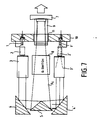
- FIG. 7 represents an alternative embodiment according to the invention in which a pressurized gas cell 9 of the RAMAN type is provided, which placed on the path of the common beam Fc is pumped by it.
- This RAMAN cell 9 makes it possible to carry out a frequency conversion.
- Nd YAG power laser working in triggered mode (Q-Switch)
- Q-Switch triggered mode
- the insertion of a RAMAN cell makes it possible to obtain a compact system which can be pumped by laser diodes and working at 1.06 ⁇ m or 1.53 ⁇ m and also providing the two wavelengths.
- RAMAN cell in the cavity makes it possible to benefit from the high density of intra-cavity power to obtain an efficient frequency transfer of the pump wave centered for example at 1.064 ⁇ m on the Stokes wave of methane at 1.53 ⁇ m. It suffices to evacuate the methane or to decrease the pressure of this gas in the cell to obtain a source working at 1.064 ⁇ m.
- the invention thus described therefore relates to a laser structure architecture providing for a distribution of the amplifying medium and a grouping of the pumping laser diodes on the same surface.
Landscapes
- Physics & Mathematics (AREA)
- Electromagnetism (AREA)
- Engineering & Computer Science (AREA)
- Plasma & Fusion (AREA)
- Optics & Photonics (AREA)
- Lasers (AREA)
Claims (13)
- Leistungslaser, der von Laserdioden gepumpt wird und enthält:- mindestens zwei Laserdioden (1, 1'), die einen Pumpstrahl (Fp) aussenden,- mindestens zwei Verstärkungsmilieus (3, 3'), die je mit einer Laserdiode (1, 1') gekoppelt sind und je eine Eingangsseite (30) besitzen, über die sie den von der zugeordneten Laserdiode (1, 1') ausgesandten Pumpstrahl empfangen, während ein Ausgangsstrahl (Fs, Fs') über eine Ausgangsseite (31) ausgegeben wird,- ein optisches Koppelsystem (4, 4', 5), das die Ausgangsstrahlen (Fs, Fs'), die von den Verstärkungsmilieus ausgesandt wurden, empfängt und sie in einem gemeinsamen Strahl (Fc) weiterleitet,- einen Ausgangsspiegel (7), der im Verlauf des gemeinsamen Strahls (Fc) liegt,wobei jede Eingangsseite (30) so ausgebildet ist, daß sie den von einer Laserdiode (1, 1') empfangenen Pumpstrahl (Fp) durchläßt und den Ausgangsstrahl (Fs, Fs') des Verstärkungsmilieus reflektiert, wobei die verschiedenen Eingangsseiten so mit dem Ausgangsspiegel (7) einen optischen Hohlraum bilden.
- Leistungslaser nach Anspruch 1, dadurch gekennzeichnet, daß die beiden Laserdioden (1, 1') und die Verstärkungsmilieus (3, 3') symmetrisch bezüglich einer Achse (XX') angeordnet sind, und daß das optische Koppelsystem erste Spiegel (4, 4') in Zuordnung zu jedem Verstärkungsmilieu (3, 3'), die bezüglich der Richtung des Ausgangsstrahls (Fs, Fs') des Verstärkungsmilieus geneigt und symmetrisch bezüglich der Achse (XX') angeordnet sind, sowie zweite Spiegel aufweist, die ebenfalls symmetrisch bezüglich der Achse (XX') angeordnet sind, die Ausgangsstrahlen (Fs, Fs'), die von den ersten Spiegeln reflektiert wurden, empfangen und sie im wesentlichen in Richtung der Achse (XX') umlenken, wobei der Ausgangsspiegel (7) zu dieser Achse (XX') fluchtet.
- Leistungslaser nach Anspruch 1, dadurch gekennzeichnet, daß er eine Mehrzahl von Laserdioden (1, 1') und von Verstärkungsmilieus (3, 3') besitzt, die entlang von Mantellinien eines fiktiven Zylinders mit der Achse (XX') angeordnet sind, und daß das optische Koppelsystem (4, 4', 5) eine erste reflektierende Vorrichtung mit einem konischen reflektierenden Kranz (40), dessen Achse die Achse (XX') des Zylinders ist und der die Ausgangsstrahlen der verschiedenen Verstärkungsmilieus zur Achse (XX') des Zylinders umlenkt, sowie eine zweite reflektierende Vorrichtung mit einer konischen reflektierenden Oberfläche besitzt, die gemäß der Achse (XX') des Zylinders angeordnet ist und die Ausgangsstrahlen zur Zylinderachse (XX') umlenkt, wobei der Ausgangsspiegel in Flucht zu dieser Achse (XX') angeordnet ist.
- Leistungslaser nach Anspruch 3, dadurch gekennzeichnet, daß die Pumpwelle (Fp) jeder Laserdiode gemäß einer bestimmten Richtung der Zylinderachse (XX') orientiert ist, während die zweite reflektierende Vorrichtung (5) so angeordnet ist, daß der aus dem optischen Hohlraum in Richtung zum Ausgangsspiegel (7) austretende Strahl (Fc') in derselben Richtung der Zylinderachse (XX') orientiert ist.
- Leistungslaser nach Anspruch 3, dadurch gekennzeichnet, daß die Pumpwelle (Fp) jeder Laserdiode in einer bestimmten Richtung entlang der Zylinderachse (XX') orientiert ist, während die zweite reflektierende Vorrichtung (5) so angeordnet ist, daß der aus dem optischen Hohlraum in Richtung zum Ausgangsspiegel (7) austretende Strahl (Fc') entgegengesetzt der bestimmten Richtung der Zylinderachse (XX') verläuft.
- Leistungslaser nach Anspruch 1, dadurch gekennzeichnet, daß die Laserdioden auf einem gemeinsamen metallischen Sockel (10) sitzen, der den mechanischen Halt der Dioden, die Verteilung der Speiseströme für die Dioden und den Wärmeaustausch mit Hilfe von Radiatoren (11) gewährleistet, die auf einer Seite des Metallsockels (10) montiert sind.
- Leistungslaser nach Anspruch 1, dadurch gekennzeichnet, daß er λ/2-Lamellen enthält, die in den Hohlraum eingesetzt sind.
- Leistungslaser nach Anspruch 1, dadurch gekennzeichnet, daß er einen Schalter des Typs Q-Switch (8) enthält, der in die Strecke des gemeinsamen Strahls (Fc) eingefügt ist.
- Leistungslaser nach Anspruch 3, dadurch gekennzeichnet, daß er einen Steuerstrahl (FA) besitzt, der entlang einer Mantellinie des Zylinders verläuft und in derselben Richtung wie die von den Laserdioden (1, 1') ausgesandten Strahlen orientiert ist.
- Leistungslaser nach Anspruch 3, dadurch gekennzeichnet, daß er anstelle irgendeines der Verstärker einen Meisterlaser (15, 16, 17) enthält, der einen Steuerstrahl (FA) aussendet.
- Leistungslaser nach Anspruch 3, dadurch gekennzeichnet, daß er im Verlauf jedes Ausgangsstrahls (Fs, Fs') und in der Nähe jedes Verstärkungsmilieus einen Frequenzverdoppler enthält.
- Leistungslaser nach Anspruch 1, dadurch gekennzeichnet, daß die verschiedenen Verstärkungsmilieus aus Materialien unterschiedlicher Art bestehen.
- Leistungslaser nach Anspruch 1, dadurch gekennzeichnet, daß er in dem optischen Hohlraum, und zwar in der Strecke des gemeinsamen Strahls (Fc), eine Zelle mit Gas unter Druck vom RAMAN-Typ enthält.
Applications Claiming Priority (2)
| Application Number | Priority Date | Filing Date | Title |
|---|---|---|---|
| FR8907079 | 1989-05-30 | ||
| FR8907079A FR2647973B1 (fr) | 1989-05-30 | 1989-05-30 | Lasers de puissance pompes par diodes lasers |
Publications (2)
| Publication Number | Publication Date |
|---|---|
| EP0401064A1 EP0401064A1 (de) | 1990-12-05 |
| EP0401064B1 true EP0401064B1 (de) | 1993-08-25 |
Family
ID=9382150
Family Applications (1)
| Application Number | Title | Priority Date | Filing Date |
|---|---|---|---|
| EP90401212A Expired - Lifetime EP0401064B1 (de) | 1989-05-30 | 1990-05-07 | Laser-Dioden-gepumpter Leistungs-Laser |
Country Status (4)
| Country | Link |
|---|---|
| US (1) | US5077750A (de) |
| EP (1) | EP0401064B1 (de) |
| DE (1) | DE69002874T2 (de) |
| FR (1) | FR2647973B1 (de) |
Families Citing this family (41)
| Publication number | Priority date | Publication date | Assignee | Title |
|---|---|---|---|---|
| ES2142803T3 (es) * | 1990-08-01 | 2000-05-01 | Diomed Ltd | Fuente luminosa de alta potencia. |
| AT404199B (de) * | 1991-06-11 | 1998-09-25 | Schroeder Kurt Dipl Ing | Optischer resonator für koaxialen hochleistungslaser |
| FR2679050B1 (fr) * | 1991-07-09 | 1994-08-26 | Thomson Csf | Dispositifs d'optique non lineaire. |
| US5299222A (en) * | 1992-03-11 | 1994-03-29 | Lightwave Electronics | Multiple diode laser stack for pumping a solid-state laser |
| US5272708A (en) * | 1992-10-30 | 1993-12-21 | The United States Of America As Represented By The Secretary Of The Navy | Two-micron modelocked laser system |
| US5528612A (en) * | 1993-11-19 | 1996-06-18 | The United States Of America As Represented By The Secretary Of The Navy | Laser with multiple gain elements |
| US5526372A (en) * | 1994-08-05 | 1996-06-11 | The United States Of America As Represented By The United States Department Of Energy | High energy bursts from a solid state laser operated in the heat capacity limited regime |
| FR2725081B1 (fr) * | 1994-09-23 | 1996-11-15 | Thomson Csf | Source optique compacte, basee sur le doublage de frequence d'un laser et auto-stabilisee par depeuplement de la pompe |
| US6215807B1 (en) * | 1998-02-24 | 2001-04-10 | Northeast Science & Technology | Coherent multiple beam laser system |
| US6324320B1 (en) | 1998-03-17 | 2001-11-27 | Polaroid Corporation | Optical apparatus for producing a high-brightness multi-laser radiation source |
| US6075912A (en) * | 1998-03-17 | 2000-06-13 | Polaroid Corporation | Apparatus for coupling radiation beams into an optical waveguide |
| FR2784185B1 (fr) | 1998-10-06 | 2001-02-02 | Thomson Csf | Dispositif pour l'harmonisation entre une voie d'emission laser et une voie passive d'observation |
| FR2796211B1 (fr) | 1999-07-09 | 2001-10-12 | Thomson Csf | Cavite optique instable pour faisceau laser |
| FR2811148B1 (fr) | 2000-06-30 | 2006-07-21 | Thomson Csf | Laser pompe et milieu laser optimise |
| FR2814281B1 (fr) * | 2000-09-19 | 2003-08-29 | Thomson Lcd | Matrice active tft pour capteur optique comportant une couche semi-conductrice photosensible, et capteur optique comportant une telle matrice |
| FR2825463B1 (fr) * | 2001-05-30 | 2003-09-12 | Thales Sa | Gyrometre laser etat solide comportant un bloc resonateur |
| JP4128092B2 (ja) * | 2003-02-21 | 2008-07-30 | 株式会社トプコン | 固体レーザ装置 |
| JP4190325B2 (ja) * | 2003-03-24 | 2008-12-03 | 株式会社トプコン | 固体レーザ装置及び固体レーザ装置によるレーザ照射方法 |
| US20070116077A1 (en) * | 2005-11-22 | 2007-05-24 | Nlight Photonics Corporation | Vertically displaced stack of multi-mode single emitter laser diodes |
| US20070217468A1 (en) * | 2006-03-20 | 2007-09-20 | Nlight Photonics Corporation | Laser diode package utilizing a laser diode stack |
| US20070116071A1 (en) * | 2005-11-22 | 2007-05-24 | Nlight Photonics Corporation | Modular diode laser assembly |
| US7443895B2 (en) * | 2005-11-22 | 2008-10-28 | Nlight Photonics Corporation | Modular diode laser assembly |
| US20070217467A1 (en) * | 2006-03-20 | 2007-09-20 | Nlight Photonics Corporation | Laser diode package utilizing a laser diode stack |
| US20070217471A1 (en) * | 2006-03-20 | 2007-09-20 | Nlight Photonics Corporation | Laser diode stack utilizing a non-conductive submount |
| US7586963B2 (en) * | 2005-11-22 | 2009-09-08 | Nlight Photonics Corporation | Modular diode laser assembly |
| US20070115617A1 (en) * | 2005-11-22 | 2007-05-24 | Nlight Photonics Corporation | Modular assembly utilizing laser diode subassemblies with winged mounting blocks |
| US7420996B2 (en) * | 2005-11-22 | 2008-09-02 | Nlight Photonics Corporation | Modular diode laser assembly |
| US7436868B2 (en) * | 2005-11-22 | 2008-10-14 | Nlight Photonics Corporation | Modular diode laser assembly |
| US20070217469A1 (en) * | 2006-03-20 | 2007-09-20 | Nlight Photonics Corporation | Laser diode stack side-pumped solid state laser |
| US20070217470A1 (en) * | 2006-03-20 | 2007-09-20 | Nlight Photonics Corporation | Laser diode stack end-pumped solid state laser |
| DE102010009048A1 (de) * | 2010-02-23 | 2011-08-25 | LPKF Laser & Electronics AG, 30827 | Laseranordnung |
| US8891579B1 (en) | 2011-12-16 | 2014-11-18 | Nlight Photonics Corporation | Laser diode apparatus utilizing reflecting slow axis collimators |
| US9478941B2 (en) * | 2012-04-26 | 2016-10-25 | Koninklijke Philips N.V. | Optically pumped solid state laser device with self-aligning pump optics |
| US9720145B2 (en) | 2014-03-06 | 2017-08-01 | Nlight, Inc. | High brightness multijunction diode stacking |
| US9705289B2 (en) | 2014-03-06 | 2017-07-11 | Nlight, Inc. | High brightness multijunction diode stacking |
| US10761276B2 (en) | 2015-05-15 | 2020-09-01 | Nlight, Inc. | Passively aligned crossed-cylinder objective assembly |
| EP3417340A1 (de) | 2016-02-16 | 2018-12-26 | NLIGHT, Inc. | Passiv ausgerichtetes einzelelementteleskop für verbesserte pakethelligkeit |
| WO2017161334A1 (en) | 2016-03-18 | 2017-09-21 | Nlight, Inc. | Spectrally multiplexing diode pump modules to improve brightness |
| WO2018119125A1 (en) | 2016-12-23 | 2018-06-28 | Nlight, Inc. | Low cost optical pump laser package |
| US10763640B2 (en) | 2017-04-24 | 2020-09-01 | Nlight, Inc. | Low swap two-phase cooled diode laser package |
| US10833482B2 (en) | 2018-02-06 | 2020-11-10 | Nlight, Inc. | Diode laser apparatus with FAC lens out-of-plane beam steering |
Family Cites Families (6)
| Publication number | Priority date | Publication date | Assignee | Title |
|---|---|---|---|---|
| US3496487A (en) * | 1966-07-05 | 1970-02-17 | Union Carbide Corp | Addition of laser beams in multiple laser systems |
| FR1556589A (de) * | 1967-03-01 | 1969-02-07 | ||
| US3753145A (en) * | 1972-06-26 | 1973-08-14 | Bell Telephone Labor Inc | Compact end-pumped solid-state laser |
| US4025172A (en) * | 1975-10-09 | 1977-05-24 | United Technologies Corporation | Compound unstable resonator |
| JPS55166984A (en) * | 1979-06-14 | 1980-12-26 | Matsushita Electric Ind Co Ltd | Multi-beam laser |
| US4901330A (en) * | 1988-07-20 | 1990-02-13 | Amoco Corporation | Optically pumped laser |
-
1989
- 1989-05-30 FR FR8907079A patent/FR2647973B1/fr not_active Expired - Lifetime
-
1990
- 1990-05-07 DE DE90401212T patent/DE69002874T2/de not_active Expired - Fee Related
- 1990-05-07 EP EP90401212A patent/EP0401064B1/de not_active Expired - Lifetime
- 1990-05-24 US US07/527,892 patent/US5077750A/en not_active Expired - Fee Related
Also Published As
| Publication number | Publication date |
|---|---|
| US5077750A (en) | 1991-12-31 |
| FR2647973B1 (fr) | 1991-08-16 |
| DE69002874D1 (de) | 1993-09-30 |
| DE69002874T2 (de) | 1993-12-23 |
| FR2647973A1 (fr) | 1990-12-07 |
| EP0401064A1 (de) | 1990-12-05 |
Similar Documents
| Publication | Publication Date | Title |
|---|---|---|
| EP0401064A1 (de) | Laser-Dioden-gepumpter Leistungs-Laser | |
| KR100375850B1 (ko) | 고전력 레이저 장치 | |
| US4890289A (en) | Fiber coupled diode pumped moving solid state laser | |
| US4739507A (en) | Diode end pumped laser and harmonic generator using same | |
| US6192062B1 (en) | Beam combining of diode laser array elements for high brightness and power | |
| US5123025A (en) | Miniature optical source | |
| FR2676147A1 (fr) | Micro laser auto-doublant. | |
| EP0408406A1 (de) | Abstimmbare Hochleistungs-Laserquelle | |
| EP0390662A1 (de) | Hochleistungs-Laser mit Steuerung der Richtung der Ausgangsstrahlung | |
| EP0493235A1 (de) | Hochenergie-Festkörperlaser | |
| FR2665307A1 (fr) | Systeme laser adapte. | |
| US5084882A (en) | Face pumped, looped fibre bundle, phased array laser oscillator | |
| FR2666699A1 (fr) | Laser a guides optiques couples. | |
| FR2784809A1 (fr) | Amplificateur optique de puissance a guide d'onde planaire pompe optiquement et laser de puissance utilisant cet amplificateur | |
| EP0421854A1 (de) | Hochleistungslaserquelle mit optischer Steuerung der Strahlabtastung | |
| US4987376A (en) | Frequency shifted laser transmitter | |
| FR2826191A1 (fr) | Source laser stabilisee en frequence et adaptee pour etre utilisee comme etalon de frequence en particulier dans le domaine des telecommunications | |
| EP0199793A1 (de) | Integraler ramanlaser mit einem einzelnen spiegel. | |
| EP0303667A1 (de) | Phasenzwangsgekoppelter laser | |
| FR2781613A1 (fr) | Laser en espace libre avec sortie fibre autoalignee | |
| FR2785098A1 (fr) | Laser solide pompe par diode laser | |
| RU2182739C2 (ru) | Микролазер (варианты) | |
| EP3082203A1 (de) | Anpassbares impulslaser-emissionssystem | |
| FR2756110A1 (fr) | Oscillateur optique a agilite de pointage et source laser utilisant cet oscillateur optique | |
| FR2739732A1 (fr) | Dispositif d'amplification optique |
Legal Events
| Date | Code | Title | Description |
|---|---|---|---|
| PUAI | Public reference made under article 153(3) epc to a published international application that has entered the european phase |
Free format text: ORIGINAL CODE: 0009012 |
|
| AK | Designated contracting states |
Kind code of ref document: A1 Designated state(s): DE GB IT |
|
| 17P | Request for examination filed |
Effective date: 19910322 |
|
| 17Q | First examination report despatched |
Effective date: 19921208 |
|
| GRAA | (expected) grant |
Free format text: ORIGINAL CODE: 0009210 |
|
| AK | Designated contracting states |
Kind code of ref document: B1 Designated state(s): DE GB IT |
|
| RIN1 | Information on inventor provided before grant (corrected) |
Inventor name: PAPUCHON, MICHEL Inventor name: POCHOLLE, JEAN-PAUL |
|
| ITF | It: translation for a ep patent filed | ||
| REF | Corresponds to: |
Ref document number: 69002874 Country of ref document: DE Date of ref document: 19930930 |
|
| GBT | Gb: translation of ep patent filed (gb section 77(6)(a)/1977) |
Effective date: 19931006 |
|
| RAP2 | Party data changed (patent owner data changed or rights of a patent transferred) |
Owner name: THOMSON-CSF |
|
| PLBE | No opposition filed within time limit |
Free format text: ORIGINAL CODE: 0009261 |
|
| STAA | Information on the status of an ep patent application or granted ep patent |
Free format text: STATUS: NO OPPOSITION FILED WITHIN TIME LIMIT |
|
| 26N | No opposition filed | ||
| PGFP | Annual fee paid to national office [announced via postgrant information from national office to epo] |
Ref country code: GB Payment date: 19960419 Year of fee payment: 7 |
|
| PGFP | Annual fee paid to national office [announced via postgrant information from national office to epo] |
Ref country code: DE Payment date: 19960425 Year of fee payment: 7 |
|
| PG25 | Lapsed in a contracting state [announced via postgrant information from national office to epo] |
Ref country code: GB Effective date: 19970507 |
|
| GBPC | Gb: european patent ceased through non-payment of renewal fee |
Effective date: 19970507 |
|
| PG25 | Lapsed in a contracting state [announced via postgrant information from national office to epo] |
Ref country code: DE Free format text: LAPSE BECAUSE OF NON-PAYMENT OF DUE FEES Effective date: 19980203 |
|
| PG25 | Lapsed in a contracting state [announced via postgrant information from national office to epo] |
Ref country code: IT Free format text: LAPSE BECAUSE OF NON-PAYMENT OF DUE FEES;WARNING: LAPSES OF ITALIAN PATENTS WITH EFFECTIVE DATE BEFORE 2007 MAY HAVE OCCURRED AT ANY TIME BEFORE 2007. THE CORRECT EFFECTIVE DATE MAY BE DIFFERENT FROM THE ONE RECORDED. Effective date: 20050507 |