EP0401164A1 - Procédé de contrôle d'un traitement thermique avec pénétration de carbone - Google Patents
Procédé de contrôle d'un traitement thermique avec pénétration de carbone Download PDFInfo
- Publication number
- EP0401164A1 EP0401164A1 EP90810375A EP90810375A EP0401164A1 EP 0401164 A1 EP0401164 A1 EP 0401164A1 EP 90810375 A EP90810375 A EP 90810375A EP 90810375 A EP90810375 A EP 90810375A EP 0401164 A1 EP0401164 A1 EP 0401164A1
- Authority
- EP
- European Patent Office
- Prior art keywords
- conductor
- reducing gas
- atmosphere
- segment
- carbon
- Prior art date
- Legal status (The legal status is an assumption and is not a legal conclusion. Google has not performed a legal analysis and makes no representation as to the accuracy of the status listed.)
- Granted
Links
- 229910052799 carbon Inorganic materials 0.000 title claims abstract description 42
- OKTJSMMVPCPJKN-UHFFFAOYSA-N Carbon Chemical compound [C] OKTJSMMVPCPJKN-UHFFFAOYSA-N 0.000 title claims abstract description 39
- 238000000034 method Methods 0.000 title claims description 25
- 238000009792 diffusion process Methods 0.000 title 1
- 238000007669 thermal treatment Methods 0.000 title 1
- 239000004020 conductor Substances 0.000 claims abstract description 39
- 239000000523 sample Substances 0.000 claims abstract description 17
- 239000011810 insulating material Substances 0.000 claims abstract 3
- 238000005259 measurement Methods 0.000 claims description 11
- 238000005261 decarburization Methods 0.000 claims description 6
- 239000002184 metal Substances 0.000 claims description 5
- 229910052751 metal Inorganic materials 0.000 claims description 5
- 238000010438 heat treatment Methods 0.000 claims description 4
- 230000035515 penetration Effects 0.000 claims description 4
- CWYNVVGOOAEACU-UHFFFAOYSA-N Fe2+ Chemical compound [Fe+2] CWYNVVGOOAEACU-UHFFFAOYSA-N 0.000 claims description 3
- 238000011282 treatment Methods 0.000 claims description 3
- RYGMFSIKBFXOCR-UHFFFAOYSA-N Copper Chemical compound [Cu] RYGMFSIKBFXOCR-UHFFFAOYSA-N 0.000 claims description 2
- WYTGDNHDOZPMIW-RCBQFDQVSA-N alstonine Natural products C1=CC2=C3C=CC=CC3=NC2=C2N1C[C@H]1[C@H](C)OC=C(C(=O)OC)[C@H]1C2 WYTGDNHDOZPMIW-RCBQFDQVSA-N 0.000 claims description 2
- 229910052802 copper Inorganic materials 0.000 claims description 2
- 239000010949 copper Substances 0.000 claims description 2
- 239000000203 mixture Substances 0.000 claims description 2
- 230000001681 protective effect Effects 0.000 claims description 2
- 230000000694 effects Effects 0.000 claims 1
- 239000012530 fluid Substances 0.000 claims 1
- 239000000463 material Substances 0.000 claims 1
- 230000008878 coupling Effects 0.000 abstract 1
- 238000010168 coupling process Methods 0.000 abstract 1
- 238000005859 coupling reaction Methods 0.000 abstract 1
- 239000007789 gas Substances 0.000 description 18
- 238000004458 analytical method Methods 0.000 description 4
- 230000004907 flux Effects 0.000 description 4
- 230000008569 process Effects 0.000 description 4
- 238000005255 carburizing Methods 0.000 description 3
- 238000006243 chemical reaction Methods 0.000 description 2
- 238000005516 engineering process Methods 0.000 description 2
- 229930195733 hydrocarbon Natural products 0.000 description 2
- 150000002430 hydrocarbons Chemical class 0.000 description 2
- 239000004215 Carbon black (E152) Substances 0.000 description 1
- 229910000831 Steel Inorganic materials 0.000 description 1
- 238000009529 body temperature measurement Methods 0.000 description 1
- 150000001721 carbon Chemical class 0.000 description 1
- 230000008859 change Effects 0.000 description 1
- 238000005336 cracking Methods 0.000 description 1
- 238000000354 decomposition reaction Methods 0.000 description 1
- 238000011161 development Methods 0.000 description 1
- 230000018109 developmental process Effects 0.000 description 1
- 229940082150 encore Drugs 0.000 description 1
- 239000011888 foil Substances 0.000 description 1
- 239000000446 fuel Substances 0.000 description 1
- 239000002737 fuel gas Substances 0.000 description 1
- 238000004868 gas analysis Methods 0.000 description 1
- 230000006872 improvement Effects 0.000 description 1
- 238000011065 in-situ storage Methods 0.000 description 1
- 238000002347 injection Methods 0.000 description 1
- 239000007924 injection Substances 0.000 description 1
- 238000009434 installation Methods 0.000 description 1
- 238000000691 measurement method Methods 0.000 description 1
- 238000012544 monitoring process Methods 0.000 description 1
- 239000000615 nonconductor Substances 0.000 description 1
- 230000003647 oxidation Effects 0.000 description 1
- 238000007254 oxidation reaction Methods 0.000 description 1
- 230000033116 oxidation-reduction process Effects 0.000 description 1
- 238000011160 research Methods 0.000 description 1
- 230000004044 response Effects 0.000 description 1
- 238000010517 secondary reaction Methods 0.000 description 1
- 230000035939 shock Effects 0.000 description 1
- 239000010959 steel Substances 0.000 description 1
- 238000012546 transfer Methods 0.000 description 1
- 238000009489 vacuum treatment Methods 0.000 description 1
- 230000004584 weight gain Effects 0.000 description 1
- 235000019786 weight gain Nutrition 0.000 description 1
- 238000003466 welding Methods 0.000 description 1
Images


Classifications
-
- G—PHYSICS
- G01—MEASURING; TESTING
- G01N—INVESTIGATING OR ANALYSING MATERIALS BY DETERMINING THEIR CHEMICAL OR PHYSICAL PROPERTIES
- G01N27/00—Investigating or analysing materials by the use of electric, electrochemical, or magnetic means
- G01N27/02—Investigating or analysing materials by the use of electric, electrochemical, or magnetic means by investigating impedance
- G01N27/04—Investigating or analysing materials by the use of electric, electrochemical, or magnetic means by investigating impedance by investigating resistance
- G01N27/12—Investigating or analysing materials by the use of electric, electrochemical, or magnetic means by investigating impedance by investigating resistance of a solid body in dependence upon absorption of a fluid; of a solid body in dependence upon reaction with a fluid, for detecting components in the fluid
-
- C—CHEMISTRY; METALLURGY
- C23—COATING METALLIC MATERIAL; COATING MATERIAL WITH METALLIC MATERIAL; CHEMICAL SURFACE TREATMENT; DIFFUSION TREATMENT OF METALLIC MATERIAL; COATING BY VACUUM EVAPORATION, BY SPUTTERING, BY ION IMPLANTATION OR BY CHEMICAL VAPOUR DEPOSITION, IN GENERAL; INHIBITING CORROSION OF METALLIC MATERIAL OR INCRUSTATION IN GENERAL
- C23C—COATING METALLIC MATERIAL; COATING MATERIAL WITH METALLIC MATERIAL; SURFACE TREATMENT OF METALLIC MATERIAL BY DIFFUSION INTO THE SURFACE, BY CHEMICAL CONVERSION OR SUBSTITUTION; COATING BY VACUUM EVAPORATION, BY SPUTTERING, BY ION IMPLANTATION OR BY CHEMICAL VAPOUR DEPOSITION, IN GENERAL
- C23C8/00—Solid state diffusion of only non-metal elements into metallic material surfaces; Chemical surface treatment of metallic material by reaction of the surface with a reactive gas, leaving reaction products of surface material in the coating, e.g. conversion coatings, passivation of metals
- C23C8/06—Solid state diffusion of only non-metal elements into metallic material surfaces; Chemical surface treatment of metallic material by reaction of the surface with a reactive gas, leaving reaction products of surface material in the coating, e.g. conversion coatings, passivation of metals using gases
- C23C8/08—Solid state diffusion of only non-metal elements into metallic material surfaces; Chemical surface treatment of metallic material by reaction of the surface with a reactive gas, leaving reaction products of surface material in the coating, e.g. conversion coatings, passivation of metals using gases only one element being applied
- C23C8/20—Carburising
Definitions
- the present invention relates to a process for controlling a heat treatment with carbon penetration carried out on parts placed in an oven, as well as a probe for the implementation of this process.
- the principle consists in following in real time the carbon which returns to the surface of the measuring element, either in weight gain (thermo-balance system or strip), or by gas analysis after secondary reaction of carbon with a gas in a system isolated from the reactor or by measuring the resistance of a sensor as a function of its carbon enrichment.
- the first principle established on the grounding of an element, can hardly be used in an industrial reactor, because the electronic balance is very sensitive to shocks and vibrations.
- the values are only punctual and significant of a state for a short period.
- the second method developed by Meyer and Schmidt consists in using a carbon flow probe in which the carbon diffuses from the atmosphere of the furnace in a steel tube with thin walls: inside the tube circulates a decarburizing atmosphere at base of wet N2 and H2.
- the carbon flux is determined from the CO / CO2 content of this atmosphere (see for example US-3,843,419).
- the main disadvantage of this system lies in the fact that the analysis is not done in situ and that the measurement chain based on infrared analyzers becomes complex and imprecise.
- This technology cannot be used in a vacuum reactor, because the introduction of decarburizing gas displaces gas reactions, weakens the enrichment kinetics, causes intergranular oxidation on the surface of the parts and raises the working pressure.
- Patent US-2,935,866 also describes a measurement method using the electrical resistance of conductors.
- two sensors are placed in the presence of an atmosphere with a known C content and the other of the atmosphere to be measured.
- the present invention aims to propose a method which avoids these drawbacks.
- the principle of this invention consists in using a tubular sensor in which a decarburizing atmosphere based on N2, H2, H2O, CO2 circulates. This tube being partly placed in the atmosphere of the furnace and its wall being very thin, the carbon diffuses through and combines with H2O to be evacuated from the system.
- the carbon flux is measured by the variation in resistivity of the sensor.
- the measurement of this resistance allows a continuous analysis and the advantages are multiple: - possibility of working in vacuum reactors and in a gaseous oxidation-reduction atmosphere; - continuous and precise method of analysis because it is done in the reactor; - easy interchangeability (by electrodes); - reliability and flexibility of use; - analysis based on an electrical signal without milking ment involving infrared measurements; - easy control of an installation from this system; - fast response time.
- the main object of the invention is a method of controlling a heat treatment with carbon penetration, carried out on parts placed in an oven, comprising the use of a probe for measuring the electrical resistance of a conductor placed in the presence of the furnace atmosphere, and the treatment of the resistance values obtained successively by these measurements, characterized in that a conductor of tubular shape is used, one of the faces of a segment of the conductor is placed contact with the atmosphere of the furnace and the space surrounding the other face of said segment is connected to a supply of reducing gas.
- FIGS 1 and 2 illustrate the known method of controlling a cementation heat treatment developed by M. Wünning and which was discussed at the beginning.
- the probe 1 has inside a casing 2 which crosses the wall 3 of the furnace a wire 4 of ferrous metal in the shape of a U and whose elbow constitutes a resistance 5. It also includes a thermo-couple for temperature measurement 6.
- a computing center 7 is designed so as to control the sending of a current into the resistor 5, to periodically measure the value of this resistor, to also control by a valve 8 a supply of decarburization gas in the space included inside the casing 2 and finally to control by a valve 9 the flow of carburizing gas which enters the furnace.
- a calculation program has been developed based on the resistance values measured on segment 5 of wire 4.
- the known method consists in periodically decarburizing the wire 4 so that the carbon content of this wire as a function of time the shape of the zigzag curve 10 (fig. 2) while the carbon content of the surface area of the parts follows the shape represented by the curve 11.
- the time intervals during which decarburization is performed are designated by "1" at the fig. 2.
- the decarburization of the wire 4 requires the introduction of the decarburizing gas inside the oven, so that this technology cannot be used in a vacuum reactor and has drawbacks even when the atmosphere of the oven is under pressure.
- FIG. 3 therefore generally illustrates the arrangement which allows the implementation of the method described below.
- the furnace 12 contains a charge of pieces to be cemented designated by 13.
- the probe 14 comprises a sensor which is constituted by a tubular electrical conductor 15 arranged in the shape of a U inside a support sleeve 16.
- the two ends of the tubular conductor 15 are connected to supply and discharge pipes 17 allowing the circulation in the conductor of a reducing gas.
- This circulation is controlled by one or more valves 18, themselves controlled from the control center 19.
- This control center also ensures the circulation of an electric current in the tubular conductor by the circuit 20 as well as the measurement of the electrical resistance of the conductor.
- the supply device 21, controlled by a valve 22, allows the introduction of the carburizing gas into the furnace 12.
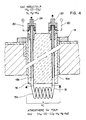
- Fig. 4 shows in more detail the constitution of the probe 14.
- the tubular conductor 15 comprises two branches 15a and 15b which extend parallel to the interior of the sleeve 16 which is a part serving both as a support, as an electrical insulator and thermal and protective for the conductor 15.
- a short segment 15c of the conductor 15, of length L, is exposed to the atmosphere of the furnace and constitutes the sensor itself. This short segment is, in the form of execution described here, wound on itself in the form of a solenoid. It could also be arranged along a serpentine line or any other route offering a large surface in contact with the atmosphere of the oven for a small footprint and unhindered circulation.
- the metal of which the conductor 15 is made is a ferrous metal of composition such that the measurement of its electrical resistance makes it possible to determine the average carbon content in the thickness of the wall of the conductor.
- the thickness of this wall will be sufficiently reduced, for example about 0.1 mm, so that the carbon can diffuse rapidly through the wall so that a state of dynamic equilibrium can be easily achieved as will be seen below.
- the two branches 15a and 15b of the tubular conductor 15 will be copper-coated externally in order to minimize the voltage drop and the change in resistance between the ends of the two branches 15a and 15b and the segment 15c.
- These two ends are in fact connected to the outside of the furnace, on the one hand to fittings 23 and 24 which are themselves connected to the reducing gas circuit 17, and on the other hand electrically to the circuit 20.
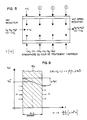
- Figures 5 and 6 illustrate the phenomenon to be controlled and give the physical quantities whose values must be processed by the computer.
- fig. 5 shows a short tubular segment which represents a part of the conductor 15 with its thin wall of cylindrical shape. If the external surface of this tubular segment is exposed to a fuel atmosphere at a determined temperature T, the carbon penetrates into the metal of the conductor and the quantity of carbon which is brought is represented by the expression mV1. This carbon diffuses through the wall and, as the interior space of the tubular conductor is in the presence of a reducing gas which circulates in the length of the conductor, this gas evacuates the carbon, the quantity of evacuated carbon being represented by expression mv2.
- Fig. 6 illustrates the equilibrium situation which is thus established.
- the graph shows the carbon content on the ordinate and the distance through the wall of the conductor 15c on the abscissa.
- the carbon content on the outside of this wall is greater than its value on the inside and the difference ⁇ % C corresponds to a mass transfer of carbon m (gram per square meter per hour).
- the value of the resistance of the conductor segment 15c depends on the temperature T, on the length L, on the thickness ⁇ X, and on the resistivity coefficient which itself depends on the carbon content.
- the value of the resistance at any instant t makes it possible to determine at this instant the average content% C of the carbon in the wall of the conductor 15c and the evolution over time of this value taking into account the flow rates of fuel gas and reducing gas mV1 and mV2. It makes it possible to determine the degree of evolution of the phenomenon of carbon penetration in the parts and therefore to follow their carburetion as shown in FIG. 7.
- the interior space of the tube has a constant carbon potential.
- a constant flow of carbon is absorbed by the constant flow of the reducing gas.
Landscapes
- Chemical & Material Sciences (AREA)
- Chemical Kinetics & Catalysis (AREA)
- Biochemistry (AREA)
- Life Sciences & Earth Sciences (AREA)
- Mechanical Engineering (AREA)
- Metallurgy (AREA)
- Organic Chemistry (AREA)
- Electrochemistry (AREA)
- Physics & Mathematics (AREA)
- General Physics & Mathematics (AREA)
- General Health & Medical Sciences (AREA)
- Analytical Chemistry (AREA)
- Materials Engineering (AREA)
- Engineering & Computer Science (AREA)
- Health & Medical Sciences (AREA)
- Immunology (AREA)
- Pathology (AREA)
- Investigating Or Analyzing Materials By The Use Of Electric Means (AREA)
- Measurement Of Resistance Or Impedance (AREA)
- Control Of Heat Treatment Processes (AREA)
- Non-Silver Salt Photosensitive Materials And Non-Silver Salt Photography (AREA)
- Crystals, And After-Treatments Of Crystals (AREA)
- Investigating And Analyzing Materials By Characteristic Methods (AREA)
- Investigating Or Analyzing Materials Using Thermal Means (AREA)
- Measuring Temperature Or Quantity Of Heat (AREA)
Abstract
Description
- La présente invention a pour objet un procédé de contrôle d'un traitement thermique avec pénétration de carbone effectué sur des pièces placées dans un four, ainsi qu'une sonde pour la mise en oeuvre de ce procédé.
- Les différents développements effectués ces dernières années dans les techniques de cémentation gazeuse ont essentiellement porté sur la réduction des temps de cycle, la qualité et la reproductibilité des traitements, ainsi que sur la consommation gazeuse et l'amélioration des conditions de sécurité.
- Ces recherches ont conduit à des atmosphères sursaturantes, souvent hors d'équilibre, mises en oeuvre dans des réacteurs agités, utilisés à la pression atmosphérique ou sous pression partielle d'hydrocarbures dans un four à vide.
- Les valeurs du potentiel carbone effectuées en mesure indirecte, à partir de gaz résiduels tels que H₂O, CO₂ ou O₂ ne peuvent plus être valablement définies.
- En traitement sous vide ou en atmosphère sursaturante, dont la libération du carbone ne passe pas par le cracking de la molécule de CO, mais par la décomposition directe d'un hydrocarbure, la notion de potentiel d'équilibre n'existe plus et pourrait être remplacée par le terme de potentiel cinétique: c'est-à-dire un enrichissement suivant une loi linéaire (dans le domaine usuel de la cémentation) en fonction du temps.
- La méthode de contrôle et de régulation parfaitement adaptée au suivi de ces réactions est la mesure en direct du flux de carbone.
- Le principe consiste à suivre en temps réel le carbone qui rentre à la surface de l'élément de mesure, soit en prise de poids (système de thermo-balance ou du feuillard), soit par analyse gazeuse après réaction secondaire du carbone avec un gaz dans un système isolé par rapport au réacteur ou par la mesure de la résistance d'un capteur en fonction de son enrichissement en carbone.
- Le premier principe, établi sur la prise de masse d'un élément, peut difficilement être utilisé dans un réacteur industriel, car la balance électronique est très sensible aux chocs et vibrations. Quant à la mesure sur clinquant, les valeurs ne sont que ponctuelles et significatives d'un état pendant une courte période.
- La deuxième méthode mise au point par Meyer et Schmidt consiste à utiliser une sonde à flux de carbone dans laquelle le carbone diffuse depuis l'atmosphère du four dans un tube en acier à parois minces: à l'intérieur du tube circule une atmosphère décarburante à base de N₂ et H₂ humides. Le flux de carbone est déterminé à partir de la teneur de cette atmosphère en CO/CO₂ (voir par exemple US-3,843,419).
- Le principal inconvénient de ce système réside dans le fait que l'analyse ne se fait pas in situ et que la chaîne de mesure basée sur des analyseurs infra-rouge devient complexe et imprécise.
- L'autre système développé par M. Wünning, utilise la méthode par résistance: un capteur en forme de fil très fin et court s'enrichit dans l'atmosphère du four et la mesure de sa résistance électrique donne une indication sur sa teneur en carbone donc sur le flux de carbone en fonction du temps. A intervalles réguliers la sonde est décarburée par une injection de H₂, H₂O et N₂ autour du capteur. (J. Wünning: Die C-Stromregelung bei der Gasaufkohlung.) HTM 40 (1985.3)
- Cette technologie n'est pas utilisable dans un réacteur sous vide, car l'introduction de gaz décarburant déplace les réactions gazeuses, affaiblit les cinétiques d'enrichissement, provoque une oxydation intergranulaire à la surface des pièces et remonte la pression de travail.
- Il faut également noter la fragilité du fil et sa complexité de montage après rupture (pour soudage).
- Le brevet US-2,935,866 (Schmidt and Wünning) décrit aussi une méthode de mesure utilisant la résistance électrique de conducteurs. Dans ce cas, deux capteurs sont mis en présence l'un d'une atmosphère à teneur en C connue et l'autre de l'atmosphère à mesurer.
- La présente invention vise à proposer un procédé qui évite ces inconvénients. Le principe de cette invention consiste à utiliser un capteur tubulaire dans lequel circule une atmosphère décarburante à base de N₂, H₂, H₂O, CO₂. Ce tube étant placé en partie dans l'atmosphère du four et sa paroi étant très fine, le carbone diffuse à travers et se combine à H₂O pour être évacué du système.
- Le flux de carbone est mesuré par la variation de résistivité du capteur. En connaissant le débit gazeux, la longueur et la surface du capteur, la mesure de cette résistance permet une analyse en continu et les avantages sont multiples:
- possibilité de travailler dans des réacteurs sous vide et dans une atmosphère gazeuse d'oxydo-réduction;
- méthode d'analyse continue et précise car elle se fait dans le réacteur;
- interchangeabilité facile (par des électrodes);
- fiabilité et souplesse d'utilisation;
- analyse basée sur un signal électrique sans traite ment faisant intervenir des mesures infra-rouge;
- pilotage aisé d'une installation à partir de ce système;
- temps de réponse rapide. - Ainsi l'objet principal de l'invention est un procédé de contrôle d'un traitement thermique avec pénétration de carbone, effectué sur des pièces placées dans un four, comportant l'utilisation d'une sonde pour la mesure de la résistance électrique d'un conducteur mis en présence de l'atmosphère du four, et le traitement des valeurs de résistance obtenues successivement par ces mesures, caractérisé en ce qu'on utilise un conducteur de forme tubulaire, on met une des faces d'un segment du conducteur en contact avec l'atmosphère du four et on raccorde l'espace avoisinant l'autre face dudit segment à une alimentation en gaz réducteur.
- On va décrire ci-après, à titre d'exemple, une forme de mise en oeuvre du procédé ainsi qu'une sonde qui constitue une forme d'exécution de l'objet secondaire de l'invention. Pour cela on se réfèrera aux dessins annexés dont:
- la fig. 1 est une vue schématique d'une sonde selon l'état antérieur de la technique;
- la fig. 2 est un graphique illustrant le fonctionnement de la sonde de la fig. 1;
- la fig. 3 est une vue schématique d'un four équipé d'une sonde selon l'invention et permettant la mise en oeuvre du procédé décrit;
- la fig. 4 est une vue en coupe à plus grande échelle de la sonde représentée à la fig. 3;
- la fig. 5 est une vue schématique en coupe à échelle encore plus grande permettant d'expliquer le déroulement du procédé et représentant un segment du conducteur tubulaire visible à la figure 4;
- la fig. 6 est une vue schématique montrant en coupe un segment de la paroi du conducteur tubulaire;
- et la fig. 7 est un graphique montrant l'évolution de la teneur en carbone dans la zone superficielle des pièces placées dans le four de la fig. 3.
- Les figures 1 et 2 illustrent le procédé connu de contrôle d'un traitement thermique de cémentation développé par M. Wünning et dont il a été question au début. La sonde 1 comporte à l'intérieur d'une enveloppe 2 qui traverse la paroi 3 du four un fil 4 de métal ferreux en forme de U et dont le coude constitue une résistance 5. Elle comporte encore un thermo-couple de mesure de température 6. Un centre de calcul 7 est conçu de façon à commander l'envoi d'un courant dans la résistance 5, à mesurer périodiquement la valeur de cette résistance, à commander également par une vanne 8 une alimentation de gaz de décarburation dans l'espace compris à l'intérieur de l'enveloppe 2 et à commander finalement par une vanne 9 le flux de gaz de cémentation qui pénètre dans le four.
- On a développé pour la mise en oeuvre de ce procédé un programme de calcul basé sur les valeurs de résistance mesurées sur le segment 5 du fil 4. Comme ce segment de fil placé dans le four a tendance à se saturer en carbone rapidement alors que la teneur en carbone de la zone superficielle des pièces à cémenter augmente progressivement au fur et à mesure que le carbone diffuse à l'intérieur des pièces, le procédé connu consiste à décarburer périodiquement le fil 4 de telle manière que la teneur en carbone de ce fil ait en fonction du temps l'allure de la courbe en zig zag 10 (fig. 2) alors que la teneur en carbone de la zone superficielle des pièces suit l'allure représentée par la courbe 11. Les intervalles de temps durant lesquels la décarburation est effectuée sont désignés par "1" à la fig. 2.
- Comme on le voit, la décarburation du fil 4 nécessite l'introduction du gaz décarburant à l'intérieur du four, de sorte que cette technologie n'est pas utilisable dans un réacteur sous vide et présente des inconvénients même lorsque l'atmosphère du four est en pression.
- La figure 3 illustre donc de façon générale l'agencement qui permet la mise en oeuvre du procédé décrit ci-après. Le four 12 contient une charge de pièces à cémenter désignée par 13. La sonde 14 comporte un capteur qui est constitué par un conducteur électrique tubulaire 15 disposé en forme de U à l'intérieur d'un manchon de support 16. Les deux extrémités du conducteur tubulaire 15 sont raccordées à des tuyaux d'alimentation et d'évacuation 17 permettant la circulation dans le conducteur d'un gaz réducteur. Cette circulation est commandée par une ou plusieurs vannes 18, commandées elles-mêmes à partir du centre de commande 19. Ce centre de commande assure aussi la circulation d'un courant électrique dans le conducteur tubulaire par le circuit 20 ainsi que la mesure de la résistance électrique du conducteur.
- Le dispositif d'alimentation 21, commandé par une vanne 22, permet l'introduction du gaz de cémentation dans le four 12.
- La fig. 4 montre plus en détail la constitution de la sonde 14. Le conducteur tubulaire 15 comporte deux branches 15a et 15b qui s'étendent parallèlement à l'intérieur du manchon 16 qui est une pièce servant à la fois de support, d'isolant électrique et thermique et de protection pour le conducteur 15. Un court segment 15c du conducteur 15, de longueur L, est exposé à l'atmosphère du four et constitue le capteur proprement dit. Ce court segment est, dans la forme d'exécution décrite ici, enroulé sur lui-même en forme de solénoïde. Il pourrait aussi être disposé selon une ligne en serpentine ou tout autre tracé offrant une grande surface au contact de l'atmosphère du four pour un faible encombrement et une circulation non entravée. Le métal dont le conducteur 15 est constitué est un métal ferreux de composition telle que la mesure de sa résistance électrique permet de déterminer la teneur en carbone moyenne dans l'épaisseur de la paroi du conducteur. L'épaisseur de cette paroi sera suffisament réduite, par exemple environ 0.1 mm, pour que le carbone puisse diffuser rapidement à travers la paroi afin qu'un état d'équilibre dynamique puisse être réalisé facilement comme on le verra plus loin.
- De préférence les deux branches 15a et 15b du conducteur tubulaire 15 seront cuivrées extérieurement afin de réduire au minimum la chute de tension et la modification de résistance entre les extrémités des deux branches 15a et 15b et le segment 15c. Ces deux extrémités sont en effet connectées à l'extérieur du four, d'une part à des raccords 23 et 24 qui sont reliés eux-mêmes au circuit de gaz réducteur 17, et d'autre part électriquement au circuit 20.
- Le procédé décrit peut être mis en oeuvre au cours de l'opération de cémentation soit de façon continue, soit de manière intermittente. Les figures 5 et 6 illustrent le phénomène qu'il s'agit de contrôler et donnent les grandeurs physiques dont les valeurs doivent être traitées par l'ordinateur. A la fig. 5 on a représenté un court segment tubulaire qui représente une partie du conducteur 15 avec sa paroi mince de forme cylindrique. Si la surface extérieure de ce segment tubulaire est exposée à une atmosphère carburante à une température déterminée T, le carbone pénétre dans le métal du conducteur et la quantité de carbone qui est apportée est représentée par l'expression mV₁. Ce carbone diffuse à travers la paroi et, comme l'espace intérieur du conducteur tubulaire se trouve en présence d'un gaz réducteur qui circule dans la longueur du conducteur, ce gaz évacue le carbone, la quantité de carbone évacuée étant représentée par l'expression mv2.
- La fig. 6 illustre la situation d'équilibre qui s'établit ainsi. Sur le graphique on a représenté en ordonnée la teneur en carbone et en abscisse la distance à travers la paroi du conducteur 15c. La teneur en carbone sur la face extérieure de cette paroi est supérieure à sa valeur sur la face intérieure et la différence Δ %C correspond à un transfert de masse de carbone m (gramme par mètre carré et par heure).
- La valeur de la résistance du segment de conducteur 15c dépend de la température T, de la longueur L, de l'épaisseur Δ X, et du coefficient de résistivité qui dépend lui-même de la teneur en carbone. Ainsi la valeur de la résistance à un instant quelconque t permet de déterminer à cet instant la teneur moyenne %C du carbone dans la paroi du conducteur 15c et l'évolution au cours du temps de cette valeur en tenant compte des débits de gaz carburant et de gaz réducteur mV₁ et mV₂. Elle permet de déterminer le degré d'évolution du phénomène de pénétration de carbone dans les pièces et par conséquent de suivre leur carburation telle qu'elle est représentée par la fig. 7.
- Lorsque les conditions d'équilibre sont réalisées, l'espace intérieur du tube comporte un potentiel carbone constant. Un flux constant de carbone est absorbé par le débit constant du gaz réducteur.
Claims (9)
Priority Applications (1)
| Application Number | Priority Date | Filing Date | Title |
|---|---|---|---|
| AT90810375T ATE101413T1 (de) | 1989-06-01 | 1990-05-23 | Verfahren zum kontrollieren einer thermischen behandlung mit c-diffusion. |
Applications Claiming Priority (2)
| Application Number | Priority Date | Filing Date | Title |
|---|---|---|---|
| CH2059/89 | 1989-06-01 | ||
| CH205989 | 1989-06-01 |
Publications (2)
| Publication Number | Publication Date |
|---|---|
| EP0401164A1 true EP0401164A1 (fr) | 1990-12-05 |
| EP0401164B1 EP0401164B1 (fr) | 1994-02-09 |
Family
ID=4224952
Family Applications (1)
| Application Number | Title | Priority Date | Filing Date |
|---|---|---|---|
| EP90810375A Expired - Lifetime EP0401164B1 (fr) | 1989-06-01 | 1990-05-23 | Procédé de contrôle d'un traitement thermique avec pénétration de carbone |
Country Status (4)
| Country | Link |
|---|---|
| US (1) | US5064620A (fr) |
| EP (1) | EP0401164B1 (fr) |
| AT (1) | ATE101413T1 (fr) |
| DE (1) | DE69006542T2 (fr) |
Cited By (3)
| Publication number | Priority date | Publication date | Assignee | Title |
|---|---|---|---|---|
| EP1306462A3 (fr) * | 2001-10-23 | 2003-10-29 | Schwäbische Härtetechnik Ulm GmbH | Procédé et installation pour mesurer et reguler l'atmosphère de cémentation dans une installation de cémentation sous vide |
| DE102011110084A1 (de) | 2011-08-12 | 2013-02-14 | Hanomag Härtecenter GmbH | Messeinrichtung |
| CN114778794A (zh) * | 2022-03-29 | 2022-07-22 | 生态环境部南京环境科学研究所 | 一种用于湿地生态系统的碳通量测定装置 |
Families Citing this family (6)
| Publication number | Priority date | Publication date | Assignee | Title |
|---|---|---|---|---|
| US5284526A (en) * | 1992-12-22 | 1994-02-08 | Air Products And Chemicals, Inc. | Integrated process for producing atmospheres suitable for heat treating from non-cryogenically generated nitrogen |
| US6125891A (en) * | 1996-03-15 | 2000-10-03 | Silicon Carbide Products, Inc. | Refractory u-bends and methods of manufacture |
| DE10242616A1 (de) * | 2002-09-13 | 2004-03-25 | Linde Ag | Verfahren und Vorrichtung zum Unterdruckaufkohlen |
| US9109277B2 (en) | 2011-01-10 | 2015-08-18 | Air Products And Chemicals, Inc. | Method and apparatus for heat treating a metal |
| CA3015805A1 (fr) * | 2017-08-28 | 2019-02-28 | Institut National De La Recherche Scientifique | Methode et systeme de fabrication de cristaux au moyen de faisceaux de particules accelerees au laser ou de sources secondaires |
| CN120539158B (zh) * | 2025-05-19 | 2025-12-02 | 长缆科技集团股份有限公司 | 一种高压电缆中间接头脱碳检验方法 |
Citations (2)
| Publication number | Priority date | Publication date | Assignee | Title |
|---|---|---|---|---|
| US2935866A (en) * | 1956-12-20 | 1960-05-10 | Indugas Fa | Apparatus for measuring the carbon level of furnace gases |
| US3843419A (en) * | 1970-05-12 | 1974-10-22 | Ludwig Ofag Indugas Gmbh | Method of and apparatus for carburizing steel bodies |
Family Cites Families (1)
| Publication number | Priority date | Publication date | Assignee | Title |
|---|---|---|---|---|
| DE3411605C2 (de) * | 1984-03-29 | 1986-07-17 | Joachim Dr.-Ing. 7250 Leonberg Wünning | Verfahren und Einrichtung zur Gasaufkohlung von Stahl |
-
1990
- 1990-05-23 AT AT90810375T patent/ATE101413T1/de not_active IP Right Cessation
- 1990-05-23 DE DE69006542T patent/DE69006542T2/de not_active Expired - Lifetime
- 1990-05-23 US US07/527,319 patent/US5064620A/en not_active Expired - Fee Related
- 1990-05-23 EP EP90810375A patent/EP0401164B1/fr not_active Expired - Lifetime
Patent Citations (2)
| Publication number | Priority date | Publication date | Assignee | Title |
|---|---|---|---|---|
| US2935866A (en) * | 1956-12-20 | 1960-05-10 | Indugas Fa | Apparatus for measuring the carbon level of furnace gases |
| US3843419A (en) * | 1970-05-12 | 1974-10-22 | Ludwig Ofag Indugas Gmbh | Method of and apparatus for carburizing steel bodies |
Non-Patent Citations (1)
| Title |
|---|
| HÄRTEREI TECHNISCHE MITTEILUNGEN, vol. 40, no. 3, mai-juin 1985, pages 104-106, Munich, DE; J. WÜNNING: "Die C-stromregelung als Ergänzung oder Ersatz für die C-Pegelregelung bei der Gasaufkohlung" * |
Cited By (3)
| Publication number | Priority date | Publication date | Assignee | Title |
|---|---|---|---|---|
| EP1306462A3 (fr) * | 2001-10-23 | 2003-10-29 | Schwäbische Härtetechnik Ulm GmbH | Procédé et installation pour mesurer et reguler l'atmosphère de cémentation dans une installation de cémentation sous vide |
| DE102011110084A1 (de) | 2011-08-12 | 2013-02-14 | Hanomag Härtecenter GmbH | Messeinrichtung |
| CN114778794A (zh) * | 2022-03-29 | 2022-07-22 | 生态环境部南京环境科学研究所 | 一种用于湿地生态系统的碳通量测定装置 |
Also Published As
| Publication number | Publication date |
|---|---|
| EP0401164B1 (fr) | 1994-02-09 |
| DE69006542T2 (de) | 1994-08-04 |
| ATE101413T1 (de) | 1994-02-15 |
| US5064620A (en) | 1991-11-12 |
| DE69006542D1 (de) | 1994-03-24 |
Similar Documents
| Publication | Publication Date | Title |
|---|---|---|
| EP0401164B1 (fr) | Procédé de contrôle d'un traitement thermique avec pénétration de carbone | |
| US3463005A (en) | Immersion molten metal sampler device | |
| US2839594A (en) | Contact thermocouple assembly | |
| EP0024566A1 (fr) | Appareil pour l'analyse de l'oxygène, de l'azote et de l'hydrogène contenus dans des métaux | |
| EP0066516A1 (fr) | Dispositif de surveillance de l'état du réfrigérant d'un réacteur nucléaire de puissance | |
| Frech et al. | On the determination of total mercury in natural gases using the amalgamation technique and cold vapour atomic absorption spectrometry | |
| MX9602789A (es) | Uso de polimeros en composiciones detergentes liquidas que contienen abrillantadores para evitar la formacion de manchas en las telas. | |
| Nicholson | Rapid thermal-decomposition technique for the atomic-absorption determination of mercury in rocks, soils and sediments | |
| EP0117230B1 (fr) | Sonde pour la mesure de la pression partielle de l'oxygène dans une atmosphère de gaz | |
| FR2684185A1 (fr) | Appareil pour recueillir et liberer des matieres condensables et appareil et procede pour analyser des matieres macromoleculaires. | |
| EP0054012B1 (fr) | Procédé de traitement d'un échantillon d'acier | |
| US3279888A (en) | Method of and apparatus for determining the oxygen content of metals | |
| US4450723A (en) | Multi-sample surface area measurement | |
| FR2466026A1 (fr) | Procede de mesure d'un flux neutronique continu et appareil pour la mise en oeuvre de ce procede | |
| EP0110778B1 (fr) | Dispositif de mesure de la puissance dans un réacteur nucléaire | |
| FR2591343A1 (fr) | Procede pour determiner le rapport oxygene/metal dans un oxyde utilise comme combustible nucleaire | |
| SU1008278A1 (ru) | Многопозиционный датчик дл активного контрол процессов химико-термического упрочнени металлов и сплавов | |
| US3891467A (en) | Thermocouple with a diffused chromium casing | |
| US2980513A (en) | Combustibles-in-air instrument | |
| EP0604275B1 (fr) | Procédé et dispositif pour la protection d'instruments de mesure dans une atmosphère corrosive chaude | |
| EP0195726B1 (fr) | Dispositif de mesure du flux de chaleur émis par un four métallurgique | |
| FR2565692A1 (fr) | Dispositif d'analyse de la teneur en oxygene de l'atmosphere d'un four, notamment de traitement thermique des aciers | |
| FR2465221A1 (fr) | Dispositif d'analyse thermique des materiaux a l'aide de l'effet thermoelectrique et son utilisation | |
| Fanciullo | Thermocouple Development Lithium-Cooled Reactor Experiment | |
| US3442118A (en) | Device for testing a body of fluid |
Legal Events
| Date | Code | Title | Description |
|---|---|---|---|
| PUAI | Public reference made under article 153(3) epc to a published international application that has entered the european phase |
Free format text: ORIGINAL CODE: 0009012 |
|
| AK | Designated contracting states |
Kind code of ref document: A1 Designated state(s): AT CH DE ES FR GB IT LI |
|
| 17P | Request for examination filed |
Effective date: 19910420 |
|
| 17Q | First examination report despatched |
Effective date: 19930401 |
|
| GRAA | (expected) grant |
Free format text: ORIGINAL CODE: 0009210 |
|
| AK | Designated contracting states |
Kind code of ref document: B1 Designated state(s): AT CH DE ES FR GB IT LI |
|
| PG25 | Lapsed in a contracting state [announced via postgrant information from national office to epo] |
Ref country code: IT Free format text: LAPSE BECAUSE OF FAILURE TO SUBMIT A TRANSLATION OF THE DESCRIPTION OR TO PAY THE FEE WITHIN THE PRE;WARNING: LAPSES OF ITALIAN PATENTS WITH EFFECTIVE DATE BEFORE 2007 MAY HAVE OCCURRED AT ANY TIME BEFORE 2007. THE CORRECT EFFECTIVE DATE MAY BE DIFFERENT FROM THE ONE RECORDED.SCRIBED TIME-LIMIT Effective date: 19940209 Ref country code: ES Free format text: THE PATENT HAS BEEN ANNULLED BY A DECISION OF A NATIONAL AUTHORITY Effective date: 19940209 Ref country code: GB Effective date: 19940209 |
|
| REF | Corresponds to: |
Ref document number: 101413 Country of ref document: AT Date of ref document: 19940215 Kind code of ref document: T |
|
| REF | Corresponds to: |
Ref document number: 69006542 Country of ref document: DE Date of ref document: 19940324 |
|
| GBV | Gb: ep patent (uk) treated as always having been void in accordance with gb section 77(7)/1977 [no translation filed] |
Effective date: 19940209 |
|
| PLBE | No opposition filed within time limit |
Free format text: ORIGINAL CODE: 0009261 |
|
| STAA | Information on the status of an ep patent application or granted ep patent |
Free format text: STATUS: NO OPPOSITION FILED WITHIN TIME LIMIT |
|
| 26N | No opposition filed | ||
| REG | Reference to a national code |
Ref country code: FR Ref legal event code: ST |
|
| REG | Reference to a national code |
Ref country code: FR Ref legal event code: RN |
|
| REG | Reference to a national code |
Ref country code: FR Ref legal event code: D3 |
|
| PGFP | Annual fee paid to national office [announced via postgrant information from national office to epo] |
Ref country code: FR Payment date: 20080716 Year of fee payment: 19 |
|
| REG | Reference to a national code |
Ref country code: FR Ref legal event code: ST Effective date: 20090119 |
|
| PG25 | Lapsed in a contracting state [announced via postgrant information from national office to epo] |
Ref country code: FR Free format text: LAPSE BECAUSE OF NON-PAYMENT OF DUE FEES Effective date: 20080602 |
|
| PGFP | Annual fee paid to national office [announced via postgrant information from national office to epo] |
Ref country code: DE Payment date: 20090528 Year of fee payment: 20 Ref country code: AT Payment date: 20090529 Year of fee payment: 20 |
|
| PGFP | Annual fee paid to national office [announced via postgrant information from national office to epo] |
Ref country code: CH Payment date: 20090527 Year of fee payment: 20 |
|
| REG | Reference to a national code |
Ref country code: CH Ref legal event code: PL |
|
| PG25 | Lapsed in a contracting state [announced via postgrant information from national office to epo] |
Ref country code: DE Free format text: LAPSE BECAUSE OF EXPIRATION OF PROTECTION Effective date: 20100523 |