EP0401171A2 - Bande de support pour appareils de scellement actionnés par poudre - Google Patents
Bande de support pour appareils de scellement actionnés par poudre Download PDFInfo
- Publication number
- EP0401171A2 EP0401171A2 EP90810389A EP90810389A EP0401171A2 EP 0401171 A2 EP0401171 A2 EP 0401171A2 EP 90810389 A EP90810389 A EP 90810389A EP 90810389 A EP90810389 A EP 90810389A EP 0401171 A2 EP0401171 A2 EP 0401171A2
- Authority
- EP
- European Patent Office
- Prior art keywords
- carrier strip
- setting direction
- nails
- receiving bores
- strip according
- Prior art date
- Legal status (The legal status is an assumption and is not a legal conclusion. Google has not performed a legal analysis and makes no representation as to the accuracy of the status listed.)
- Granted
Links
- 239000000843 powder Substances 0.000 title 1
- 239000011324 bead Substances 0.000 claims description 26
- 238000003780 insertion Methods 0.000 description 2
- 230000037431 insertion Effects 0.000 description 2
- 238000010276 construction Methods 0.000 description 1
- 230000005489 elastic deformation Effects 0.000 description 1
- 230000001771 impaired effect Effects 0.000 description 1
- 238000000034 method Methods 0.000 description 1
- 238000000926 separation method Methods 0.000 description 1
- 230000035939 shock Effects 0.000 description 1
Images
Classifications
-
- B—PERFORMING OPERATIONS; TRANSPORTING
- B25—HAND TOOLS; PORTABLE POWER-DRIVEN TOOLS; MANIPULATORS
- B25C—HAND-HELD NAILING OR STAPLING TOOLS; MANUALLY OPERATED PORTABLE STAPLING TOOLS
- B25C1/00—Hand-held nailing tools; Nail feeding devices
- B25C1/08—Hand-held nailing tools; Nail feeding devices operated by combustion pressure
- B25C1/10—Hand-held nailing tools; Nail feeding devices operated by combustion pressure generated by detonation of a cartridge
- B25C1/16—Cartridges specially adapted for impact tools; Cartridge and bolts units
-
- F—MECHANICAL ENGINEERING; LIGHTING; HEATING; WEAPONS; BLASTING
- F16—ENGINEERING ELEMENTS AND UNITS; GENERAL MEASURES FOR PRODUCING AND MAINTAINING EFFECTIVE FUNCTIONING OF MACHINES OR INSTALLATIONS; THERMAL INSULATION IN GENERAL
- F16B—DEVICES FOR FASTENING OR SECURING CONSTRUCTIONAL ELEMENTS OR MACHINE PARTS TOGETHER, e.g. NAILS, BOLTS, CIRCLIPS, CLAMPS, CLIPS OR WEDGES; JOINTS OR JOINTING
- F16B15/00—Nails; Staples
- F16B15/08—Nails; Staples formed in integral series but easily separable
-
- F—MECHANICAL ENGINEERING; LIGHTING; HEATING; WEAPONS; BLASTING
- F16—ENGINEERING ELEMENTS AND UNITS; GENERAL MEASURES FOR PRODUCING AND MAINTAINING EFFECTIVE FUNCTIONING OF MACHINES OR INSTALLATIONS; THERMAL INSULATION IN GENERAL
- F16B—DEVICES FOR FASTENING OR SECURING CONSTRUCTIONAL ELEMENTS OR MACHINE PARTS TOGETHER, e.g. NAILS, BOLTS, CIRCLIPS, CLAMPS, CLIPS OR WEDGES; JOINTS OR JOINTING
- F16B19/00—Bolts without screw-thread; Pins, including deformable elements; Rivets
- F16B19/14—Bolts or the like for shooting into concrete constructions, metal walls or the like by means of detonation-operated nailing tools
Definitions
- the invention relates to a carrier strip for powder-operated setting tools, with uniformly spaced receiving bores in which nails are slidably mounted, the nails having a head and a shaft with two spaced-apart guide disks for storing the nails in the receiving bores, the outer diameter of the head corresponds at most to the inner diameter of the receiving bores.
- a carrier strip with nails known from DE-P 38 06 624.6 enables the use of simple device-side transport and locking devices and prevents the occurrence of empty strokes of the device-side driving piston.
- the nails are held in the receiving bores of the carrier strip by using the elasticity of the carrier strip. This requires precise matching of the mounting holes and guide disks.
- the invention has for its object to provide a carrier strip that allows storage of nails without precise matching of mounting holes and guide washers, and also in the case of strong shocks or the like sudden impact, as can occur in rough construction site use, shifting the nails before setting prevented.
- At least one of the guide disks is provided with stops supporting the nails in and against the setting direction, at least the setting direction-side stop for moving the nails within the receiving bore being overcome under setting conditions.
- the stops ensure a reliable axial deflection which is not impaired by vibrations or the like support of the nails in the carrier strip, even if the diameter of the receiving bores is equal to or slightly larger than the diameter of the guide disks. Due to the functional separation of the guiding and holding function, the carrier strip does not require a precise diameter adjustment of the mounting holes with the guide washers of the nails.
- the stops are pushed radially outward by the guide disks with radial elastic deformation of the carrier strip, for example made of plastic.
- the nails with the guide disks can thus leave the carrier strip for the setting process under setting conditions.
- a stop is expediently provided for each of the guide disks.
- the stops can thus be offset from one another in the axial direction of the receiving bore in accordance with the distance between the guide disks, as a result of which the holding function of the stops is not mutually influenced, which is particularly advantageous when inserting the nails into the receiving bores.
- the stop on the setting direction is preferably provided for the guide disc on the setting direction in the setting direction and the stop lying against the setting direction is provided for the guide disc arranged against the setting direction against the setting direction.
- the stop provided in the setting direction is advantageously offset in its axial projection corresponding to the receiving bore with respect to the stop provided against the setting direction.
- the stops are preferably designed as annular beads which project into the clear width of the receiving bores and run along a normal plane to the axis of the receiving bores forms, which leads to a linear support of the guide discs.
- the annular beads can protrude radially into the clear width of the receiving bores by two or more tenths of a millimeter.
- the annular beads advantageously extend over a circumferential angle of 30 ° to 90 °. This configuration of the annular beads means that their radial protrusion into the clear width of the receiving bores can be kept small, while at the same time ensuring sufficient support for the guide disks.
- annular beads are expediently arranged in the circumferential direction of the receiving bores.
- two annular beads each forming a stop can be arranged diametrically opposite one another. While such a pair of annular beads supports the guide disk on the setting direction, another pair of annular beads can support the other guide disk against the setting direction. Both pairs of annular beads can be arranged offset from one another by 90 °. The nails are thus held evenly in the mounting holes.
- the annular beads advantageously have a sawtooth-shaped cross section in a sectional plane running along the axis of the receiving bores.
- the short sawtooth flank of the stops expediently faces the guide disks. This ensures that after insertion of the nails by sliding the guide disks along the long sawtooth flank, the guide disks are supported by the short sawtooth flank of the ring beads.
- the short sawtooth flank can extend normal to the axis of the receiving bores, which means that a correspondingly large radial dimension of the ring beads Axial support capable of absorbing force is achieved.
- Openings are advantageously provided between the annular beads provided in the opposite direction to the opposite direction of the end of the strip, the length of which runs along the receiving bore and extends from the end side directed in the opposite direction to the annular beads provided in the opposite direction.
- the parts remaining between the openings form cup-shaped fingers which are articulated on the carrier strip and can be elastically bent outwards. This is advantageous for the insertion of the nails into the receiving bores in that the guide disks can pass through the annular beads provided against the setting direction with springs open and the fingers then spring back.
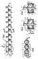
- the carrier strip 1 shown in FIG. 1 serves to hold nails 2 arranged at equal intervals from one another.
- the nails 2 are seated in receiving bores 3 of the carrier strip 1.
- the nails 2 shown overall in FIGS. 3 and 4 have a head 4 and a shaft 5.
- Two guide disks 6, 7 are seated on the shaft 5 at an axial distance from one another.
- the guide disks 6, 7 have the same diameter as the receiving bores 3 and thus ensure a concentric, axially parallel guidance of the nails 2 in the receiving bores 3.
- the guide discs 6, 7 also serve to axially hold the nails 2 in the carrier strip 1.
- the guide discs 6, 7 are supported axially against stops of the carrier strip 1 in the form of opposing ring beads 8 in the setting direction and further ring beads 9 against the setting direction.
- the annular beads 8 and 9 have a sawtooth-shaped cross section in a sectional plane running along the axis of the receiving bores 3 according to FIGS. 3 and 4.
- the shorter sawtooth flank 8a, 9a faces the guide disks 6, 7 and thus serves as a support shoulder.
- the carrier strip 1 is provided with openings 11 which are open toward the end face facing away from the setting direction and have a length L corresponding to approximately 30% of the length of the receiving bores 3.
- openings 11 which are open toward the end face facing away from the setting direction and have a length L corresponding to approximately 30% of the length of the receiving bores 3.
- the annular beads 9 facing away from the setting direction are arranged on the inside in the region of the free end.
- the parts 12 articulated on one side spring radially outwards when the nails 2 are inserted into the receiving bores 3 with the engagement of the guide disks 6 and back again for support purposes.
Landscapes
- Engineering & Computer Science (AREA)
- General Engineering & Computer Science (AREA)
- Mechanical Engineering (AREA)
- Chemical & Material Sciences (AREA)
- Combustion & Propulsion (AREA)
- Portable Nailing Machines And Staplers (AREA)
- Coating Apparatus (AREA)
- Electrostatic Spraying Apparatus (AREA)
- Automatic Assembly (AREA)
- Continuous Casting (AREA)
- Powder Metallurgy (AREA)
- Mounting, Exchange, And Manufacturing Of Dies (AREA)
- Food Preservation Except Freezing, Refrigeration, And Drying (AREA)
- Basic Packing Technique (AREA)
- Registering, Tensioning, Guiding Webs, And Rollers Therefor (AREA)
- Finish Polishing, Edge Sharpening, And Grinding By Specific Grinding Devices (AREA)
- Treating Waste Gases (AREA)
- Vaporization, Distillation, Condensation, Sublimation, And Cold Traps (AREA)
- Yarns And Mechanical Finishing Of Yarns Or Ropes (AREA)
- Preliminary Treatment Of Fibers (AREA)
- Automotive Seat Belt Assembly (AREA)
- Pulleys (AREA)
Applications Claiming Priority (2)
| Application Number | Priority Date | Filing Date | Title |
|---|---|---|---|
| DE3917846 | 1989-06-01 | ||
| DE3917846A DE3917846A1 (de) | 1989-06-01 | 1989-06-01 | Traegerstreifen fuer pulverkraftbetriebene setzgeraete |
Publications (3)
| Publication Number | Publication Date |
|---|---|
| EP0401171A2 true EP0401171A2 (fr) | 1990-12-05 |
| EP0401171A3 EP0401171A3 (fr) | 1992-04-01 |
| EP0401171B1 EP0401171B1 (fr) | 1994-04-27 |
Family
ID=6381827
Family Applications (1)
| Application Number | Title | Priority Date | Filing Date |
|---|---|---|---|
| EP90810389A Expired - Lifetime EP0401171B1 (fr) | 1989-06-01 | 1990-05-29 | Bande de support pour appareils de scellement actionnés par poudre |
Country Status (11)
| Country | Link |
|---|---|
| US (1) | US5046396A (fr) |
| EP (1) | EP0401171B1 (fr) |
| KR (1) | KR950011682B1 (fr) |
| AT (1) | ATE105054T1 (fr) |
| AU (1) | AU617617B2 (fr) |
| CA (1) | CA2017928C (fr) |
| DE (2) | DE3917846A1 (fr) |
| DK (1) | DK0401171T3 (fr) |
| ES (1) | ES2053160T3 (fr) |
| FI (1) | FI92428C (fr) |
| HU (1) | HU213990B (fr) |
Cited By (1)
| Publication number | Priority date | Publication date | Assignee | Title |
|---|---|---|---|---|
| EP3674569A1 (fr) * | 2018-12-27 | 2020-07-01 | Max Co., Ltd. | Attache de connexion |
Families Citing this family (20)
| Publication number | Priority date | Publication date | Assignee | Title |
|---|---|---|---|---|
| USD356479S (en) | 1993-07-08 | 1995-03-21 | Chen Ho T | Screw holding belt |
| ES2146664T3 (es) * | 1993-10-01 | 2000-08-16 | Henrob Ltd | Cinta portadora para elementos de fijacion. |
| DE19602789A1 (de) * | 1996-01-26 | 1997-07-31 | Hilti Ag | Nagelstreifen für Setzgerät |
| US5811717A (en) * | 1996-08-21 | 1998-09-22 | Illinois Tool Works Inc. | Powder-actuated tool cartridge clip with position indicator mark |
| US5931622A (en) * | 1997-10-07 | 1999-08-03 | Illinois Tool Works Inc. | Fastener assembly with lateral end extension |
| DE19854573A1 (de) | 1998-11-26 | 2000-05-31 | Basf Ag | Verfahren zur Nachvernetzung von Hydrogelen mit 2-Oxo-tetrahydro-1,3-oxazinen |
| USD446101S1 (en) | 1999-11-22 | 2001-08-07 | Michael P. Cone | Orienting and driving system for roofing nails |
| USD472783S1 (en) | 2000-08-21 | 2003-04-08 | Powers Fasteners, Inc. | Nail holder and nail holder strip for use with nail driving tools |
| US6814231B2 (en) | 2002-01-23 | 2004-11-09 | Illinois Tool Works Inc. | Strip of collated fasteners for fastener-driving tool |
| DE10225943A1 (de) | 2002-06-11 | 2004-01-08 | Basf Ag | Verfahren zur Herstellung von Estern von Polyalkoholen |
| US6676353B1 (en) * | 2002-07-15 | 2004-01-13 | Harry M. Haytayan | Self-drilling, self-tapping screws |
| KR100549454B1 (ko) * | 2002-08-22 | 2006-02-10 | 한넷텔레콤(주) | 이동통신 중계장치 및 그 제어방법 |
| US6779959B1 (en) * | 2003-04-21 | 2004-08-24 | Testo Industry Corp. | Belt of nails for nailers |
| US7654389B2 (en) * | 2004-04-14 | 2010-02-02 | Flexible Steel Lacing Company | Rivet collating system including rivet holder and method of forming the same |
| EP1736508A1 (fr) | 2005-06-22 | 2006-12-27 | Basf Aktiengesellschaft | Polymères formant des hydrogels avec perméabilité améliorée et haute capacité d'absorption |
| US20080124187A1 (en) * | 2006-11-08 | 2008-05-29 | Haytayan Harry M | Self-drilling, self-tapping screw fasteners |
| DE202007005605U1 (de) * | 2007-04-18 | 2008-10-09 | Sfs Intec Holding Ag | Gurtband zum Magazinieren von Schrauben und Vorrichtung zum Verarbeiten desselben |
| US10093476B2 (en) | 2014-12-02 | 2018-10-09 | Flexible Steel Lacing Company | Collating system for conveyor belt rivets and method |
| EP3501749A1 (fr) * | 2017-12-20 | 2019-06-26 | HILTI Aktiengesellschaft | Bandes d'éléments de fixation |
| EP3822027A1 (fr) * | 2019-11-12 | 2021-05-19 | Hilti Aktiengesellschaft | Dispositif de séparation, chargeur et système de fixation |
Family Cites Families (7)
| Publication number | Priority date | Publication date | Assignee | Title |
|---|---|---|---|---|
| DE1625316A1 (de) * | 1967-07-20 | 1970-06-11 | Holz Elektro Feinmechanik | Bolzen fuer Schubkolben-Schiessgeraete |
| FR1600417A (fr) * | 1968-08-05 | 1970-07-27 | ||
| US3670942A (en) * | 1970-10-15 | 1972-06-20 | Omark Industries Inc | Automatic feeding of fasteners |
| FR2282306A1 (fr) * | 1974-08-07 | 1976-03-19 | Otalu Sa | Rivet sur bande |
| US4106618A (en) * | 1975-12-15 | 1978-08-15 | Haytayan Harry M | Nail assemblies |
| DE3606514A1 (de) * | 1986-02-28 | 1987-09-03 | Hilti Ag | Pulverkraftbetriebenes bolzensetzgeraet |
| DE3806624A1 (de) * | 1988-03-02 | 1989-09-14 | Hilti Ag | Traegerstreifen |
-
1989
- 1989-06-01 DE DE3917846A patent/DE3917846A1/de not_active Withdrawn
-
1990
- 1990-05-29 DE DE59005503T patent/DE59005503D1/de not_active Expired - Lifetime
- 1990-05-29 ES ES90810389T patent/ES2053160T3/es not_active Expired - Lifetime
- 1990-05-29 DK DK90810389.8T patent/DK0401171T3/da active
- 1990-05-29 EP EP90810389A patent/EP0401171B1/fr not_active Expired - Lifetime
- 1990-05-29 AT AT9090810389T patent/ATE105054T1/de not_active IP Right Cessation
- 1990-05-30 US US07/530,888 patent/US5046396A/en not_active Expired - Lifetime
- 1990-05-30 FI FI902691A patent/FI92428C/fi not_active IP Right Cessation
- 1990-05-30 CA CA002017928A patent/CA2017928C/fr not_active Expired - Fee Related
- 1990-05-30 AU AU56142/90A patent/AU617617B2/en not_active Ceased
- 1990-05-31 KR KR1019900007917A patent/KR950011682B1/ko not_active Expired - Fee Related
- 1990-05-31 HU HU903283A patent/HU213990B/hu not_active IP Right Cessation
Cited By (2)
| Publication number | Priority date | Publication date | Assignee | Title |
|---|---|---|---|---|
| EP3674569A1 (fr) * | 2018-12-27 | 2020-07-01 | Max Co., Ltd. | Attache de connexion |
| US11624391B2 (en) | 2018-12-27 | 2023-04-11 | Max Co., Ltd. | Connection fastener |
Also Published As
| Publication number | Publication date |
|---|---|
| DK0401171T3 (da) | 1994-08-08 |
| CA2017928C (fr) | 1998-04-07 |
| HU903283D0 (en) | 1990-10-28 |
| EP0401171A3 (fr) | 1992-04-01 |
| FI92428C (fi) | 1994-11-10 |
| US5046396A (en) | 1991-09-10 |
| KR950011682B1 (ko) | 1995-10-07 |
| FI902691A0 (fi) | 1990-05-30 |
| HU213990B (en) | 1997-11-28 |
| AU617617B2 (en) | 1991-11-28 |
| ES2053160T3 (es) | 1994-07-16 |
| FI92428B (fi) | 1994-07-29 |
| DE3917846A1 (de) | 1990-12-06 |
| KR910000304A (ko) | 1991-01-29 |
| DE59005503D1 (de) | 1994-06-01 |
| HUT57397A (en) | 1991-11-28 |
| EP0401171B1 (fr) | 1994-04-27 |
| CA2017928A1 (fr) | 1990-12-01 |
| AU5614290A (en) | 1990-12-06 |
| ATE105054T1 (de) | 1994-05-15 |
Similar Documents
| Publication | Publication Date | Title |
|---|---|---|
| EP0401171A2 (fr) | Bande de support pour appareils de scellement actionnés par poudre | |
| DE3914120C2 (fr) | ||
| DE69520505T2 (de) | Nutenfräser | |
| EP0336089B1 (fr) | Support en forme de ruban | |
| DE10358683A1 (de) | Vorrichtung zum Verbinden eines Trägerteils und eines Anbauteils | |
| DE19827172A1 (de) | Werkzeughalter | |
| DE3638056A1 (de) | Kegelrollenlager | |
| DE8321186U1 (de) | Vorrichtung zum Befestigen von Maschinenteilen | |
| EP3191729B1 (fr) | Guidage d'un étirier d'un frein à disque à étrier flottant | |
| DE102015002712A1 (de) | Rundschaftmeißelanordnung, Sicherungsring für eine Rundschaftmeißelanordnung, Set mit einer Spannhülse und einem Sicherungsring und Verfahren zum Sichern eines Rundschaftmeißels in einem Meißelhalter | |
| DE202006020765U1 (de) | Rundschaftmeißel mit Meißelhalter | |
| EP0407733A1 (fr) | Roulement radial | |
| DE2750334C2 (fr) | ||
| DE3305419A1 (de) | Selbstsichernder zackenring | |
| EP1924378A1 (fr) | Dispositif pour realiser un couplage amovible de deux pieces | |
| EP0570442B1 (fr) | Segment de frein | |
| EP0208839A2 (fr) | Coussinet | |
| DE4306087C2 (de) | Vorschubspindelmechanismus mit einer Schwingungsdämpfungsvorrichtung | |
| DE69319093T2 (de) | Rotierendes werkzeug | |
| DE2647703C2 (de) | Verfahren und Vorrichtung zum Zusammenbau von Reibungskupplungen | |
| EP0198179A1 (fr) | Amortisseur à friction | |
| DE2406151B2 (de) | Nabenverbindung zwischen einer nabe und einer welle | |
| DE2820278B2 (de) | Federhalterung für die Membranfeder bei einem Kupplungsscheibendämpfer | |
| DE4003485A1 (de) | Werkzeugkupplung, insbesondere fuer zerspanungswerkzeuge | |
| EP0690239A1 (fr) | Elément de fixation |
Legal Events
| Date | Code | Title | Description |
|---|---|---|---|
| PUAI | Public reference made under article 153(3) epc to a published international application that has entered the european phase |
Free format text: ORIGINAL CODE: 0009012 |
|
| AK | Designated contracting states |
Kind code of ref document: A2 Designated state(s): AT BE CH DE DK ES FR GB IT LI NL SE |
|
| PUAL | Search report despatched |
Free format text: ORIGINAL CODE: 0009013 |
|
| AK | Designated contracting states |
Kind code of ref document: A3 Designated state(s): AT BE CH DE DK ES FR GB IT LI NL SE |
|
| 17P | Request for examination filed |
Effective date: 19920421 |
|
| 17Q | First examination report despatched |
Effective date: 19930405 |
|
| GRAA | (expected) grant |
Free format text: ORIGINAL CODE: 0009210 |
|
| ITF | It: translation for a ep patent filed | ||
| AK | Designated contracting states |
Kind code of ref document: B1 Designated state(s): AT BE CH DE DK ES FR GB IT LI NL SE |
|
| REF | Corresponds to: |
Ref document number: 105054 Country of ref document: AT Date of ref document: 19940515 Kind code of ref document: T |
|
| REF | Corresponds to: |
Ref document number: 59005503 Country of ref document: DE Date of ref document: 19940601 |
|
| ET | Fr: translation filed | ||
| GBT | Gb: translation of ep patent filed (gb section 77(6)(a)/1977) |
Effective date: 19940602 |
|
| REG | Reference to a national code |
Ref country code: ES Ref legal event code: FG2A Ref document number: 2053160 Country of ref document: ES Kind code of ref document: T3 |
|
| REG | Reference to a national code |
Ref country code: DK Ref legal event code: T3 |
|
| EAL | Se: european patent in force in sweden |
Ref document number: 90810389.8 |
|
| PLBE | No opposition filed within time limit |
Free format text: ORIGINAL CODE: 0009261 |
|
| STAA | Information on the status of an ep patent application or granted ep patent |
Free format text: STATUS: NO OPPOSITION FILED WITHIN TIME LIMIT |
|
| 26N | No opposition filed | ||
| REG | Reference to a national code |
Ref country code: GB Ref legal event code: IF02 |
|
| PGFP | Annual fee paid to national office [announced via postgrant information from national office to epo] |
Ref country code: DK Payment date: 20020514 Year of fee payment: 13 |
|
| PGFP | Annual fee paid to national office [announced via postgrant information from national office to epo] |
Ref country code: CH Payment date: 20020531 Year of fee payment: 13 |
|
| PGFP | Annual fee paid to national office [announced via postgrant information from national office to epo] |
Ref country code: BE Payment date: 20020717 Year of fee payment: 13 |
|
| PG25 | Lapsed in a contracting state [announced via postgrant information from national office to epo] |
Ref country code: BE Free format text: LAPSE BECAUSE OF NON-PAYMENT OF DUE FEES Effective date: 20030531 Ref country code: LI Free format text: LAPSE BECAUSE OF NON-PAYMENT OF DUE FEES Effective date: 20030531 Ref country code: CH Free format text: LAPSE BECAUSE OF NON-PAYMENT OF DUE FEES Effective date: 20030531 |
|
| BERE | Be: lapsed |
Owner name: *HILTI A.G. Effective date: 20030531 |
|
| PG25 | Lapsed in a contracting state [announced via postgrant information from national office to epo] |
Ref country code: DK Free format text: LAPSE BECAUSE OF NON-PAYMENT OF DUE FEES Effective date: 20031201 |
|
| REG | Reference to a national code |
Ref country code: CH Ref legal event code: PL |
|
| REG | Reference to a national code |
Ref country code: DK Ref legal event code: EBP |
|
| PG25 | Lapsed in a contracting state [announced via postgrant information from national office to epo] |
Ref country code: IT Free format text: LAPSE BECAUSE OF NON-PAYMENT OF DUE FEES Effective date: 20050529 |
|
| PGFP | Annual fee paid to national office [announced via postgrant information from national office to epo] |
Ref country code: ES Payment date: 20090605 Year of fee payment: 20 Ref country code: NL Payment date: 20090504 Year of fee payment: 20 |
|
| PGFP | Annual fee paid to national office [announced via postgrant information from national office to epo] |
Ref country code: SE Payment date: 20090512 Year of fee payment: 20 Ref country code: FR Payment date: 20090515 Year of fee payment: 20 Ref country code: DE Payment date: 20090511 Year of fee payment: 20 Ref country code: AT Payment date: 20090514 Year of fee payment: 20 |
|
| PGFP | Annual fee paid to national office [announced via postgrant information from national office to epo] |
Ref country code: GB Payment date: 20090527 Year of fee payment: 20 |
|
| REG | Reference to a national code |
Ref country code: NL Ref legal event code: V4 Effective date: 20100529 |
|
| EUG | Se: european patent has lapsed | ||
| REG | Reference to a national code |
Ref country code: ES Ref legal event code: FD2A Effective date: 20100531 |
|
| PG25 | Lapsed in a contracting state [announced via postgrant information from national office to epo] |
Ref country code: NL Free format text: LAPSE BECAUSE OF EXPIRATION OF PROTECTION Effective date: 20100529 |
|
| PG25 | Lapsed in a contracting state [announced via postgrant information from national office to epo] |
Ref country code: ES Free format text: LAPSE BECAUSE OF EXPIRATION OF PROTECTION Effective date: 20100531 |
|
| PG25 | Lapsed in a contracting state [announced via postgrant information from national office to epo] |
Ref country code: GB Free format text: LAPSE BECAUSE OF EXPIRATION OF PROTECTION Effective date: 20100528 |
|
| PG25 | Lapsed in a contracting state [announced via postgrant information from national office to epo] |
Ref country code: DE Free format text: LAPSE BECAUSE OF EXPIRATION OF PROTECTION Effective date: 20100529 |