EP0401178A1 - Auspufftopf für Brennkraftmaschinen zur Beseitigung von Verbrennungsrückständen - Google Patents
Auspufftopf für Brennkraftmaschinen zur Beseitigung von Verbrennungsrückständen Download PDFInfo
- Publication number
- EP0401178A1 EP0401178A1 EP90830236A EP90830236A EP0401178A1 EP 0401178 A1 EP0401178 A1 EP 0401178A1 EP 90830236 A EP90830236 A EP 90830236A EP 90830236 A EP90830236 A EP 90830236A EP 0401178 A1 EP0401178 A1 EP 0401178A1
- Authority
- EP
- European Patent Office
- Prior art keywords
- housing
- exhaust
- unburnt
- exhaust pipe
- eliminate
- Prior art date
- Legal status (The legal status is an assumption and is not a legal conclusion. Google has not performed a legal analysis and makes no representation as to the accuracy of the status listed.)
- Withdrawn
Links
Images
Classifications
-
- F—MECHANICAL ENGINEERING; LIGHTING; HEATING; WEAPONS; BLASTING
- F01—MACHINES OR ENGINES IN GENERAL; ENGINE PLANTS IN GENERAL; STEAM ENGINES
- F01N—GAS-FLOW SILENCERS OR EXHAUST APPARATUS FOR MACHINES OR ENGINES IN GENERAL; GAS-FLOW SILENCERS OR EXHAUST APPARATUS FOR INTERNAL-COMBUSTION ENGINES
- F01N3/00—Exhaust or silencing apparatus having means for purifying, rendering innocuous, or otherwise treating exhaust
- F01N3/08—Exhaust or silencing apparatus having means for purifying, rendering innocuous, or otherwise treating exhaust for rendering innocuous
- F01N3/10—Exhaust or silencing apparatus having means for purifying, rendering innocuous, or otherwise treating exhaust for rendering innocuous by thermal or catalytic conversion of noxious components of exhaust
- F01N3/24—Exhaust or silencing apparatus having means for purifying, rendering innocuous, or otherwise treating exhaust for rendering innocuous by thermal or catalytic conversion of noxious components of exhaust characterised by constructional aspects of converting apparatus
- F01N3/38—Arrangements for igniting
-
- F—MECHANICAL ENGINEERING; LIGHTING; HEATING; WEAPONS; BLASTING
- F01—MACHINES OR ENGINES IN GENERAL; ENGINE PLANTS IN GENERAL; STEAM ENGINES
- F01N—GAS-FLOW SILENCERS OR EXHAUST APPARATUS FOR MACHINES OR ENGINES IN GENERAL; GAS-FLOW SILENCERS OR EXHAUST APPARATUS FOR INTERNAL-COMBUSTION ENGINES
- F01N3/00—Exhaust or silencing apparatus having means for purifying, rendering innocuous, or otherwise treating exhaust
- F01N3/08—Exhaust or silencing apparatus having means for purifying, rendering innocuous, or otherwise treating exhaust for rendering innocuous
- F01N3/10—Exhaust or silencing apparatus having means for purifying, rendering innocuous, or otherwise treating exhaust for rendering innocuous by thermal or catalytic conversion of noxious components of exhaust
- F01N3/24—Exhaust or silencing apparatus having means for purifying, rendering innocuous, or otherwise treating exhaust for rendering innocuous by thermal or catalytic conversion of noxious components of exhaust characterised by constructional aspects of converting apparatus
- F01N3/26—Construction of thermal reactors
-
- Y—GENERAL TAGGING OF NEW TECHNOLOGICAL DEVELOPMENTS; GENERAL TAGGING OF CROSS-SECTIONAL TECHNOLOGIES SPANNING OVER SEVERAL SECTIONS OF THE IPC; TECHNICAL SUBJECTS COVERED BY FORMER USPC CROSS-REFERENCE ART COLLECTIONS [XRACs] AND DIGESTS
- Y02—TECHNOLOGIES OR APPLICATIONS FOR MITIGATION OR ADAPTATION AGAINST CLIMATE CHANGE
- Y02T—CLIMATE CHANGE MITIGATION TECHNOLOGIES RELATED TO TRANSPORTATION
- Y02T10/00—Road transport of goods or passengers
- Y02T10/10—Internal combustion engine [ICE] based vehicles
- Y02T10/12—Improving ICE efficiencies
Definitions
- the object of the invention is to provide a waste-gas exhaust head (or muffler) for internal-combustion engines, especially for automotive engines, which is apt to reduce unburnt or anyhow polluting combustion residues, thereby solving many ecological problems.
- the present exhaust head comprises, in a portion of the gas path having enlarged cross-section, and thus in which the gases have reduced speed, means able to trigger the combustion of the combustible residues eliminating the unburnt products out of the exhaust gas.
- said heated means are uncovered electrical resistances which come in contact with the exhaust gas.
- the housing of the exhaust head is thermally insulated - mostly with refractory material - owing to the presence of high internal temperatures due to said electrical resistances; an exhaust pipe leads into said housing and a terminal exhaust pipe, for the gases which have gone through the same housing, extends therefrom.
- housing - which may be cylindrical - there may be provided at least two arcuated electrical resistances formed of spiral wire, transversally disposed to the exhaust gas flow to come in contact therewith; the wires extend partially around the exhaust pipe which goes into the housing parallel to the axis thereof.
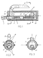
- mumeral 1 indicates the connection of the exhaust pipe coming from an internal-combustion engine, such as a petrol or other liquid fuel-powered engine, especially an automotive engine.
- Numeral 3 generically indicates the exhaust head which is developed with a peripherical skirt 5 made of metal sheet and having an internal lining of refractory material and of such a thickness as to ensure a thermal insulation, thereby reducing external heat losses and keeping the temperature of the matal skirt 5 within acceptable limits.
- 7A and 7B indicate two end portions made of refractory material which complete the above mentioned insulation. The end portion 7B may be built in the form of a mobile bottom to allow access both for the assembly and for the inspection and control of the internal members of the exhaust head.
- Numeral 9 indicates the housing with the refractory lining 7, 7A, 7B for the transit of the gases.
- the cross-section of housing 9 is much larger than the cross-section of both the connection 1 for the exhaust pipe coming from the engine, and of the one of the terminal pipe 10 for the final discharge.
- the connection 1 for the incoming exhaust gases goes through the end plate 7A and proceeds with a portion 1A parallel to the axis of the exhaust head and, in particular, of the housing 9, but is out of alignment with respect to the said axis; this extension with the portion 1A is also advantageously made of refractory material.
- the portion 1A ends close to the end plate 7B of the housing of the exhaust head 3, while the terminal 10 is placed near the end plate 7A.
- the exhaust gases travel the portion 1A within the housing 9, from the jointing connection 1 up to one end of the housing 9 and then flow back in opposite direction the full extension of the housing 9 to reach the exhaust terminal 10.
- the area of the housing 9 which is crossed by the gases, has a very large cross-section, notwithstanding the presence of portion 1A inside the exhaust pipe, thereby reducing the gas speed within the housing.
- the resistances 12 may be, in practice, coil resistances which may be heated up at least to the red colour and, anyway, to such a temperature as to trigger the combustion of residual products possibly present in the exhaust gases. The unburnt products, therefore, burns before being discharged through the terminal pipe 10, thereby eliminating the presence of pollutants in the exhaust gases which are discharged into the atmosphere.
- the resistances 12 may be supported by structural shapes 14 which are disposed side-by-side and sustain, likewise support brackets, the length 1A of the exhaust pipe which is inside the housing 9.
- the metal shapes 14 may form electrical conductors to supply the resistances 12 from connectors like those indicated by 16 (see Fig. 2) which provide an external connection for the supply of the electrical resistances; the latter being supplied by the on-board system in case of application on motor vehicles.
- the presence of the refractory insulation 7, 7A, 7B is suitable both for avoiding heat losses and for keeping a high temperature within the housing 9, where the resistances 12 must provide for an elevated temperature and where the temperature is increased also by the combustion of the unburnt products coming from the exhaust gases of the engine. Such residues are thus eliminated, as already set forth, before being discahrged and scattered outside.
- a different conformation of the exhaust head may be provided as far as the fumes path is concerned.
- the heating means may also be different. For example, provision may be made for a trigger operated by an electric arc or other.
Landscapes
- Chemical & Material Sciences (AREA)
- Engineering & Computer Science (AREA)
- Chemical Kinetics & Catalysis (AREA)
- Health & Medical Sciences (AREA)
- Toxicology (AREA)
- Combustion & Propulsion (AREA)
- Mechanical Engineering (AREA)
- General Engineering & Computer Science (AREA)
- Exhaust Silencers (AREA)
Applications Claiming Priority (2)
| Application Number | Priority Date | Filing Date | Title |
|---|---|---|---|
| IT943989 | 1989-06-02 | ||
| IT8909439A IT1233281B (it) | 1989-06-02 | 1989-06-02 | Marmitta per gas di scarico di motori endotermici, atta ad eliminare gli incombusti |
Publications (1)
| Publication Number | Publication Date |
|---|---|
| EP0401178A1 true EP0401178A1 (de) | 1990-12-05 |
Family
ID=11130162
Family Applications (1)
| Application Number | Title | Priority Date | Filing Date |
|---|---|---|---|
| EP90830236A Withdrawn EP0401178A1 (de) | 1989-06-02 | 1990-05-25 | Auspufftopf für Brennkraftmaschinen zur Beseitigung von Verbrennungsrückständen |
Country Status (2)
| Country | Link |
|---|---|
| EP (1) | EP0401178A1 (de) |
| IT (1) | IT1233281B (de) |
Cited By (1)
| Publication number | Priority date | Publication date | Assignee | Title |
|---|---|---|---|---|
| WO1998035142A1 (en) * | 1997-02-10 | 1998-08-13 | Mats Tikka | Catalytic reactor for two-stroke engines |
Citations (4)
| Publication number | Priority date | Publication date | Assignee | Title |
|---|---|---|---|---|
| US3043096A (en) * | 1961-03-14 | 1962-07-10 | Nat Exhaust Purifier Co Inc | Exhaust gas purifier and muffler |
| FR2098887A5 (de) * | 1970-07-30 | 1972-03-10 | Kafcsak Joseph | |
| GB1396607A (en) * | 1972-06-03 | 1975-06-04 | Culp N B | Exhaust gas thermal afterburning apparatus |
| US4077888A (en) * | 1975-12-08 | 1978-03-07 | John Stewart Rhoades | Arc discharge apparatus |
-
1989
- 1989-06-02 IT IT8909439A patent/IT1233281B/it active
-
1990
- 1990-05-25 EP EP90830236A patent/EP0401178A1/de not_active Withdrawn
Patent Citations (4)
| Publication number | Priority date | Publication date | Assignee | Title |
|---|---|---|---|---|
| US3043096A (en) * | 1961-03-14 | 1962-07-10 | Nat Exhaust Purifier Co Inc | Exhaust gas purifier and muffler |
| FR2098887A5 (de) * | 1970-07-30 | 1972-03-10 | Kafcsak Joseph | |
| GB1396607A (en) * | 1972-06-03 | 1975-06-04 | Culp N B | Exhaust gas thermal afterburning apparatus |
| US4077888A (en) * | 1975-12-08 | 1978-03-07 | John Stewart Rhoades | Arc discharge apparatus |
Cited By (2)
| Publication number | Priority date | Publication date | Assignee | Title |
|---|---|---|---|---|
| WO1998035142A1 (en) * | 1997-02-10 | 1998-08-13 | Mats Tikka | Catalytic reactor for two-stroke engines |
| US6216447B1 (en) | 1997-02-10 | 2001-04-17 | Mats Tikka | Two-cycle carburetor gasoline engine for snowmobiles, lawn mowers, motorcycles or outboard motors |
Also Published As
| Publication number | Publication date |
|---|---|
| IT1233281B (it) | 1992-03-26 |
| IT8909439A0 (it) | 1989-06-02 |
Similar Documents
| Publication | Publication Date | Title |
|---|---|---|
| US3211534A (en) | Exhaust control apparatus | |
| RU2141040C1 (ru) | Катализатор с электрическим нагревом | |
| KR950013644B1 (ko) | 배출가스촉매장치의 반응을 촉진시키기 위한 방법 및 장치 그리고 상기 방법을 실시하기 위한 전기로 가열되는 지지체 | |
| US5887427A (en) | Electrically insulating gas tight penetration | |
| JP2502945B2 (ja) | 噴射式内燃機関 | |
| US20170016370A1 (en) | Electrically heatable catalytic converter and method for manufacturing same | |
| JPH1089686A (ja) | グロープラグ | |
| US5536478A (en) | Electrical leads for a fluid heaters | |
| US4353208A (en) | Exhaust gas purification apparatus for an internal combustion engine of motor vehicles | |
| EP0456919A2 (de) | Katalytischer Umwandler | |
| US5618462A (en) | Electrically insulating, gas-tight leadthrough for at least one electrical conductor through a metallic sheath | |
| EP0942158B1 (de) | Heizvorrichtung für einen Abgasreinigungskatalysator | |
| EP0401178A1 (de) | Auspufftopf für Brennkraftmaschinen zur Beseitigung von Verbrennungsrückständen | |
| EP1013997A3 (de) | Brennkraftmaschine mit einem Verbrennungsheizgerät | |
| US4077888A (en) | Arc discharge apparatus | |
| CN101547731B (zh) | 汽车排放组件和制造方法 | |
| US20020053283A1 (en) | Magnetic pollution filter | |
| JP3626197B2 (ja) | 内燃機関の排気系統 | |
| JPH0676916A (ja) | 点火プラグ | |
| JPH08278027A (ja) | 予熱プラグ | |
| JP3823393B2 (ja) | グロープラグ | |
| TW472109B (en) | Device for the exhaust treatment in an internal combustion engine | |
| EP0151558A1 (de) | Partikelfilter zur Reinigung der Abgase von Verbrennungsmotoren | |
| US5325665A (en) | Catalytic converter arrangement | |
| US3661529A (en) | Combination afterburner and auxiliary muffler |
Legal Events
| Date | Code | Title | Description |
|---|---|---|---|
| PUAI | Public reference made under article 153(3) epc to a published international application that has entered the european phase |
Free format text: ORIGINAL CODE: 0009012 |
|
| AK | Designated contracting states |
Kind code of ref document: A1 Designated state(s): DE ES FR GB SE |
|
| 17P | Request for examination filed |
Effective date: 19901123 |
|
| 17Q | First examination report despatched |
Effective date: 19920409 |
|
| STAA | Information on the status of an ep patent application or granted ep patent |
Free format text: STATUS: THE APPLICATION IS DEEMED TO BE WITHDRAWN |
|
| 18D | Application deemed to be withdrawn |
Effective date: 19931026 |