EP0401180A1 - Paroi repliable - Google Patents
Paroi repliable Download PDFInfo
- Publication number
- EP0401180A1 EP0401180A1 EP90830239A EP90830239A EP0401180A1 EP 0401180 A1 EP0401180 A1 EP 0401180A1 EP 90830239 A EP90830239 A EP 90830239A EP 90830239 A EP90830239 A EP 90830239A EP 0401180 A1 EP0401180 A1 EP 0401180A1
- Authority
- EP
- European Patent Office
- Prior art keywords
- hinge
- section
- intermediate section
- panel
- panels
- Prior art date
- Legal status (The legal status is an assumption and is not a legal conclusion. Google has not performed a legal analysis and makes no representation as to the accuracy of the status listed.)
- Granted
Links
- 238000005192 partition Methods 0.000 title claims abstract description 21
- 238000009413 insulation Methods 0.000 description 5
- 230000000694 effects Effects 0.000 description 3
- 238000004519 manufacturing process Methods 0.000 description 3
- 238000012423 maintenance Methods 0.000 description 2
- 238000000638 solvent extraction Methods 0.000 description 2
- 230000006978 adaptation Effects 0.000 description 1
- 230000002411 adverse Effects 0.000 description 1
- 230000003467 diminishing effect Effects 0.000 description 1
- 239000011521 glass Substances 0.000 description 1
- 230000008595 infiltration Effects 0.000 description 1
- 238000001764 infiltration Methods 0.000 description 1
- 238000003780 insertion Methods 0.000 description 1
- 230000037431 insertion Effects 0.000 description 1
- 239000000463 material Substances 0.000 description 1
- 238000000034 method Methods 0.000 description 1
- 230000000007 visual effect Effects 0.000 description 1
- XLYOFNOQVPJJNP-UHFFFAOYSA-N water Substances O XLYOFNOQVPJJNP-UHFFFAOYSA-N 0.000 description 1
Images
Classifications
-
- E—FIXED CONSTRUCTIONS
- E06—DOORS, WINDOWS, SHUTTERS, OR ROLLER BLINDS IN GENERAL; LADDERS
- E06B—FIXED OR MOVABLE CLOSURES FOR OPENINGS IN BUILDINGS, VEHICLES, FENCES OR LIKE ENCLOSURES IN GENERAL, e.g. DOORS, WINDOWS, BLINDS, GATES
- E06B3/00—Window sashes, door leaves, or like elements for closing wall or like openings; Layout of fixed or moving closures, e.g. windows in wall or like openings; Features of rigidly-mounted outer frames relating to the mounting of wing frames
- E06B3/32—Arrangements of wings characterised by the manner of movement; Arrangements of movable wings in openings; Features of wings or frames relating solely to the manner of movement of the wing
- E06B3/48—Wings connected at their edges, e.g. foldable wings
- E06B3/481—Wings foldable in a zig-zag manner or bi-fold wings
Definitions
- the invention relates to a folding partition structure consisting in a set of adjoining panels slidable in tracks, alternated with intermediate hinge post sections and joined together by hinges that are concealed from external view.
- Numerous types of partition systems are currently marketed, which consist in folding panels designed to glide between top and bottom horizontal tracks. These folding panel systems are especially useful for partitioning off and protecting open spaces such as terrace roofs, balconies, porticoes, etc.. The panels can be stowed away one against the next in simple fashion to the end of minimizing the space taken up when not in use.
- folding panel systems of the type in question can be used advantageously to partition off internal spaces in a wide variety of ways, each such partition being swiftly removable.
- a first drawback stems from the fact that the structure of most partitions is somewhat complex and costly.
- Another folding partition structure incorporates an intermediate hinge post section, located between and articulating with each two adjacent panels.
- the upright stile sections of the panel sashes in this system are provided at each articulation with two contact surfaces contoured in the shape of an arc to a circle, each concentric with the point of articulation itself, and the intermediate section with two corresponding seals designed to engage the contact surfaces as the panels rotate. Whilst able to solve the problems of heat and sound insulation, this latter solution is still by no means free from drawbacks; in effect, such folding structures have proved slow to sell by reason of the high cost of manufacture involved in producing the particular contour of the sash stile section.
- a second disadvantage stems from the fact that tight contact must be ensured between the contoured surfaces of the panel sash stile sections and the respective seals in order to obtain good acoustic insulation during rotation of the panel; thus there is strong sliding friction between the surfaces and the seals, resulting in heavy wear on the seals.
- a further limitation affecting structures of this type is due to the fact that the extended partition can be made to follow a curved track on one side only.
- the single panel can rotate in relation to the intermediate post section through no more than 90° from the fully open position to the folded and stowed position, so that no rotation whatever is possible in the direction opposite to the folding direction.
- a first drawback stems from the fact that the pivot to which the locking ring is fitted must first be machined, and therefore requires prior adaptation to suit the type of hinge adopted.
- a second drawback stems from the fact that, in the event of the sash and frame needing to be separated from one another, the locking ring must first be removed; not only is this an operation requiring special tools, but notable additional difficulties also arise, especially with hinges installed in positions that deny easy access.
- the object of the present invention is to overcome the drawbacks mentioned above.
- a further advantage consists in the fact that the structure according to the invention can be used easily for non-rectilinear partitioning, whereby the panels, which swing to either side of the hinge centre through a certain angle, can be positioned along any given curved trajectory.
- the seals adopted are not affected by problems of wear.
- the significant proximity of the sash stile sections and the intermediate post sections, attributable to the particular arrangement of the hinge, enables the use of ordinary abutting seals.
- An additional advantage of the structure disclosed is that no relative axial movement of hinge parts can occur, and the risk of sashes being blown off by the wind is thus eliminated.
- routine maintenance of the panels is much facilitated, even of the external faces that are often difficult if not altogether impossible to reach in conventional structures, as the sashes can be lifted easily from their pivots when folded into the stowed position.
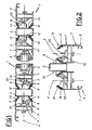
- the structure 1 consists substantially in panels 5 and intermediate sections 2 located between the panels 5.
- the panels 5 consist preferably in centred panes of glass, and sash frame members 7 surrounding the panes.
- Each intermediate section 2 connects on either hand with the adjacent panel 5 by way of a hinge 3 that is located between the longitudinal median plane 4 of the panel 5 and one or other of the two external faces 6 of the sash.
- Each hinge 3 is accommodated within the dimensional compass of the corresponding panel sash member 7, in such a way as to remain concealed from external view and thus ensure that the appearance of the panels 5 will not be adversely affected when the partition is extended.
- the positioning of the hinge 3 is advantageous in particular as it enables the upright sash members, i.e. the stile sections 7, to be brought markedly close to the corresponding intermediate sections 2, when the panels 5 are drawn out into the extended configuration of the partition.
- the seals 8 can be of different types and differently disposed.
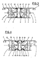
- each seal 8 is fitted directly to the intermediate section 2, anchored in relative seatings 18 located at the vertical edges. Accordingly, when the panels 5 are folded away into the stowing position, each seal 8 will be located between the flank surface 17 of the intermediate section 2 and the adjacent external face 6 of the panel 5. Positioned thus between the two surfaces, the seal 8 functions as a soft cushioning medium.
- each seal 8 is split into two matching parts 8a and 8b.
- both the intermediate section 2 and the stile section 7 afford seatings 18, 14 to accommodate the respective parts 8a and 8b.
- the seatings denoted 18 are located along the vertical edges of the intermediate section 2; the seatings denoted 14, on the other hand, are the same as in figs 1 and 2.
- This particular arrangement of the seals 8a, 8b is especially advantageous in cases where magnetic types are adopted.
- the magnetic force of attraction which persists when the lips of the seals 8a and 8b are offered to one another, is such as to ensure an efficient excluding action even with seals that have become especially worn or deformed.
- the intermediate section connects with the hinge 3 by way of an element 9 which, being appropriately profiled, allows the adjacent stile section 7 to rotate freely, but in such a way that no contact is possible geometrically between the stile and the element 9 when the panel 5 is rotated.
- the interconnecting element 9 issues from the flank 17 of the intermediate section 2 directed toward the hinge 3 and is L-shaped, thus creating a recess in which to accommodate the edge 13 of the stile section 7 when the relative panel 5 is folded into the stowed position.
- the stile sections 7 are fashioned with a rounded profile at the edges 13, in such a way as to minimize the space necessary for rotation.
- the hinge 3 is connected by way of a second element 10 with the stile section 7 of the panel.
- the two interconnecting elements 9, 10 will engage with the intermediate section 2 and the stile section 7, respectively, by way of positive sliding fittings 11 and 12.
- the elements 9 and 10 might equally well be associated removably with the sections by means of other fasteners such as screws, bolts etc.
- the fitting denoted 12 consists in a slot 16 running longitudinally and in relief along the flank 17 of the intermediate section 2.
- the side face of the slot 16 farthest from the hinge 3 is located advantageously behind and directly adjoining one of the seals 8; in this way, the face also provides a stop to check the inwardly-directed flexural movement of the seals 8, caused by wind or draught, while presenting an internal labyrinth profile to any air that may in fact infiltrate.
- the check for the seals 8 can be fashioned as illustrated in fig 2, in the form of a simple fin 15.
- a simple fin will be located, clearly enough, in the area opposite that occupied by the hinge 3 in relation to the longitudinal median plane 4 of the panel 5, and positioned longitudinally on the flank 17 of the intermediate section 2; needless to say, the fin 15 will extend continuously along the entire length of the seal 8 if its function as a stop is to be performed to best effect. Disposed thus, the fin 15 provides an effective labyrinth against any infiltration of air, water etc.
- the folding partition disclosed possesses the capacity to bend marginally, even toward the side opposite that on which the panels are folded away for stowing. Accordingly, it becomes possible for the extended partition to follow trajectories deviating on either side from the median plane 4, with equal ease.
- the hinge 3 used in the folding structure which consists essentially in a pivot and a bushing, also comprises an interference element denoted 20.
- the interference element 20 is rigidly associated with one component of the hinge assembly (pivot or bushing) and stationed outside the dimensional compass normally allowing relative axial movement of the hinge components.
- the interference element 20 is positioned so as to register with a given component of the partition structure and disallow its movement along the axis of rotation of the hinge 3.
- the interference element 20 can be embodied, as in the example illustrated, in such a way as to enter into contact with the intermediate section 2 by way of the element 9 interconnecting the section with the respective component of the hinge 3.
- the function of the interference element 20 is linked to two particular positions: a first of non-interference, in which the intermediate section 2 is easily separated from the point of articulation, and a second of interference in which movement of the relative interconnecting element 9 in an axial direction is disallowed by reason of the fact that the interference element 20 is rigidly associated with the interconnecting element 10 of the sash stile section 7, hence with the remaining component of the hinge.
- the dimensions and shape of the interference element 20 permit of selecting an angle of rotation of the panel 5 at which its movement in the axial direction will be either enabled or inhibited; moreover, the interference element 20 can be associated removably with the relative component of the hinge 3.
- the folding structure is rendered significantly more stable and safe in the extended configuration, given that freedom of relative axial movement at the various points of articulation is entirely eliminated.
- the intermediate sections 2 will become freely detachable from the sashes 5 at the respective hinge 3, automatically, when the panels are folded back.
Landscapes
- Engineering & Computer Science (AREA)
- Civil Engineering (AREA)
- Structural Engineering (AREA)
- Extensible Doors And Revolving Doors (AREA)
- Specific Sealing Or Ventilating Devices For Doors And Windows (AREA)
- Body Structure For Vehicles (AREA)
Priority Applications (1)
| Application Number | Priority Date | Filing Date | Title |
|---|---|---|---|
| AT90830239T ATE86709T1 (de) | 1989-05-30 | 1990-05-29 | Faltwand. |
Applications Claiming Priority (4)
| Application Number | Priority Date | Filing Date | Title |
|---|---|---|---|
| IT8903498A IT1234091B (it) | 1989-05-30 | 1989-05-30 | Struttura a parete pieghevole formata da una serie di ante affiancate |
| IT349989 | 1989-05-30 | ||
| IT349889 | 1989-05-30 | ||
| IT8903499A IT1234092B (it) | 1989-05-30 | 1989-05-30 | Articolazione per serramenti, atta ad inibire scorrimenti assiali dei serramenti lungo il proprio asse di rotazione in corrispondenza di un angolo di rotazione prefissato |
Publications (2)
| Publication Number | Publication Date |
|---|---|
| EP0401180A1 true EP0401180A1 (fr) | 1990-12-05 |
| EP0401180B1 EP0401180B1 (fr) | 1993-03-10 |
Family
ID=26325415
Family Applications (1)
| Application Number | Title | Priority Date | Filing Date |
|---|---|---|---|
| EP19900830239 Expired - Lifetime EP0401180B1 (fr) | 1989-05-30 | 1990-05-29 | Paroi repliable |
Country Status (6)
| Country | Link |
|---|---|
| EP (1) | EP0401180B1 (fr) |
| CA (1) | CA2017457A1 (fr) |
| DE (1) | DE69001043T2 (fr) |
| ES (1) | ES2040586T3 (fr) |
| IE (1) | IE901874A1 (fr) |
| PT (1) | PT8375U (fr) |
Cited By (4)
| Publication number | Priority date | Publication date | Assignee | Title |
|---|---|---|---|---|
| EP0537878A1 (fr) * | 1991-10-12 | 1993-04-21 | Toko Shutter Co., Ltd. | Dispositif de fermeture hermétique pour portes et fenêtres pliantes |
| AT411380B (de) * | 2001-10-31 | 2003-12-29 | Alutechnik Matauschek Gmbh | Anordnung von mindestens zwei flächigen elementen |
| GB2506968A (en) * | 2012-08-07 | 2014-04-16 | Smart Systems Ltd | Bi-folding door with internal hinges |
| WO2022047510A1 (fr) * | 2020-09-02 | 2022-03-10 | Schneider Torsysteme Gesellschaft m.b.H. | Fixation d'encadrement de porte pour porte pliante |
Families Citing this family (1)
| Publication number | Priority date | Publication date | Assignee | Title |
|---|---|---|---|---|
| AU2004201522B2 (en) * | 2004-04-13 | 2011-03-10 | Capral Limited | Improvements in or relating to doors |
Citations (7)
| Publication number | Priority date | Publication date | Assignee | Title |
|---|---|---|---|---|
| CH517888A (de) * | 1969-12-26 | 1972-01-15 | Metallurg De Saint Louis Sa So | Tür oder Fenster, bestehend aus einem Tür- bzw. Fensterflügel und einem Festrahmen aus hohlen Metallprofilen |
| US3720255A (en) * | 1970-12-11 | 1973-03-13 | E Ueda | Horizontal shutter |
| DE2602206A1 (de) * | 1975-01-27 | 1976-07-29 | Saxi A S | Falttuer oder faltwand |
| EP0014361A1 (fr) * | 1979-02-01 | 1980-08-20 | Manfred Greschbach | Porte repliable coulissante |
| DE3505267A1 (de) * | 1983-08-24 | 1986-08-21 | Adolf Dipl.-Ing. 2312 Mönkeberg Kindler | Glatt ausziehbare zweischalige faltwand |
| DE8633829U1 (de) * | 1986-12-18 | 1987-03-19 | Dieter Klaiber, Markisen-Klaiber, 76189 Karlsruhe | Faltwand |
| EP0277531A1 (fr) * | 1987-01-27 | 1988-08-10 | SCHÜCO International GmbH & Co. | Porte ou fenêtre pliante et coulissante |
-
1990
- 1990-05-24 CA CA 2017457 patent/CA2017457A1/fr not_active Abandoned
- 1990-05-24 IE IE187490A patent/IE901874A1/en unknown
- 1990-05-29 DE DE1990601043 patent/DE69001043T2/de not_active Expired - Fee Related
- 1990-05-29 EP EP19900830239 patent/EP0401180B1/fr not_active Expired - Lifetime
- 1990-05-29 ES ES90830239T patent/ES2040586T3/es not_active Expired - Lifetime
-
1991
- 1991-10-18 PT PT837591U patent/PT8375U/pt not_active IP Right Cessation
Patent Citations (7)
| Publication number | Priority date | Publication date | Assignee | Title |
|---|---|---|---|---|
| CH517888A (de) * | 1969-12-26 | 1972-01-15 | Metallurg De Saint Louis Sa So | Tür oder Fenster, bestehend aus einem Tür- bzw. Fensterflügel und einem Festrahmen aus hohlen Metallprofilen |
| US3720255A (en) * | 1970-12-11 | 1973-03-13 | E Ueda | Horizontal shutter |
| DE2602206A1 (de) * | 1975-01-27 | 1976-07-29 | Saxi A S | Falttuer oder faltwand |
| EP0014361A1 (fr) * | 1979-02-01 | 1980-08-20 | Manfred Greschbach | Porte repliable coulissante |
| DE3505267A1 (de) * | 1983-08-24 | 1986-08-21 | Adolf Dipl.-Ing. 2312 Mönkeberg Kindler | Glatt ausziehbare zweischalige faltwand |
| DE8633829U1 (de) * | 1986-12-18 | 1987-03-19 | Dieter Klaiber, Markisen-Klaiber, 76189 Karlsruhe | Faltwand |
| EP0277531A1 (fr) * | 1987-01-27 | 1988-08-10 | SCHÜCO International GmbH & Co. | Porte ou fenêtre pliante et coulissante |
Cited By (5)
| Publication number | Priority date | Publication date | Assignee | Title |
|---|---|---|---|---|
| EP0537878A1 (fr) * | 1991-10-12 | 1993-04-21 | Toko Shutter Co., Ltd. | Dispositif de fermeture hermétique pour portes et fenêtres pliantes |
| AT411380B (de) * | 2001-10-31 | 2003-12-29 | Alutechnik Matauschek Gmbh | Anordnung von mindestens zwei flächigen elementen |
| GB2506968A (en) * | 2012-08-07 | 2014-04-16 | Smart Systems Ltd | Bi-folding door with internal hinges |
| WO2022047510A1 (fr) * | 2020-09-02 | 2022-03-10 | Schneider Torsysteme Gesellschaft m.b.H. | Fixation d'encadrement de porte pour porte pliante |
| US12497822B2 (en) | 2020-09-02 | 2025-12-16 | Schneider Torsysteme Gesellschaft m.b.H | Gateframe fastening for a folding gate |
Also Published As
| Publication number | Publication date |
|---|---|
| ES2040586T3 (es) | 1993-10-16 |
| DE69001043T2 (de) | 1993-09-02 |
| IE901874A1 (en) | 1991-01-02 |
| DE69001043D1 (de) | 1993-04-15 |
| PT8375T (pt) | 1992-03-31 |
| CA2017457A1 (fr) | 1990-11-30 |
| EP0401180B1 (fr) | 1993-03-10 |
| PT8375U (pt) | 1994-10-31 |
Similar Documents
| Publication | Publication Date | Title |
|---|---|---|
| AU2002227283B2 (en) | Overhead garage door | |
| RU2113586C1 (ru) | Шарнирное приспособление | |
| US4185416A (en) | Weatherstrip | |
| US20180363345A1 (en) | Adjustable Path Guide for Movable Partition Assemblies | |
| US4663896A (en) | Window frame members | |
| US2913046A (en) | Sliding closure construction | |
| US4953261A (en) | Waterproof hinged panel assembly | |
| US20010011583A1 (en) | Combination carrier and hinge for folding panels | |
| US5088236A (en) | Pivotable glazing for a balcony | |
| US5839228A (en) | Swing-up sliding door arrangement | |
| EP0168354A1 (fr) | Système de cloison de séparation constituée d'une série de panneaux adjacents | |
| EP0401180B1 (fr) | Paroi repliable | |
| US5065544A (en) | Window assembly | |
| GB2110283A (en) | Frame for patio doors | |
| FI84645C (fi) | Svaengbar glasbelaeggning. | |
| CN209942665U (zh) | 一种防风铝合金门窗 | |
| US6997230B2 (en) | Folding device as room divider or room closure | |
| US4612727A (en) | Windows | |
| US3427747A (en) | Sliding sash assembly with storm window | |
| AU2004280215A1 (en) | Improvements in and relating to multi-fold door and window assemblies | |
| EP0080870A1 (fr) | Constructions de portes de terrasse | |
| CN221462156U (zh) | 一种折叠门 | |
| CA2083506A1 (fr) | Fenetre | |
| JPS623514Y2 (fr) | ||
| AU726943B3 (en) | Combination carrier and hinge for folding panels |
Legal Events
| Date | Code | Title | Description |
|---|---|---|---|
| PUAI | Public reference made under article 153(3) epc to a published international application that has entered the european phase |
Free format text: ORIGINAL CODE: 0009012 |
|
| AK | Designated contracting states |
Kind code of ref document: A1 Designated state(s): AT BE CH DE DK ES FR GB GR LI LU NL SE |
|
| 17P | Request for examination filed |
Effective date: 19910128 |
|
| 17Q | First examination report despatched |
Effective date: 19911223 |
|
| GRAA | (expected) grant |
Free format text: ORIGINAL CODE: 0009210 |
|
| AK | Designated contracting states |
Kind code of ref document: B1 Designated state(s): AT BE CH DE DK ES FR GB GR LI LU NL SE |
|
| PG25 | Lapsed in a contracting state [announced via postgrant information from national office to epo] |
Ref country code: SE Effective date: 19930310 Ref country code: DK Effective date: 19930310 |
|
| REF | Corresponds to: |
Ref document number: 86709 Country of ref document: AT Date of ref document: 19930315 Kind code of ref document: T |
|
| REF | Corresponds to: |
Ref document number: 69001043 Country of ref document: DE Date of ref document: 19930415 |
|
| ET | Fr: translation filed | ||
| REG | Reference to a national code |
Ref country code: GR Ref legal event code: FG4A Free format text: 3008092 |
|
| REG | Reference to a national code |
Ref country code: ES Ref legal event code: FG2A Ref document number: 2040586 Country of ref document: ES Kind code of ref document: T3 |
|
| PLBE | No opposition filed within time limit |
Free format text: ORIGINAL CODE: 0009261 |
|
| STAA | Information on the status of an ep patent application or granted ep patent |
Free format text: STATUS: NO OPPOSITION FILED WITHIN TIME LIMIT |
|
| 26N | No opposition filed | ||
| EPTA | Lu: last paid annual fee | ||
| REG | Reference to a national code |
Ref country code: GB Ref legal event code: IF02 |
|
| PGFP | Annual fee paid to national office [announced via postgrant information from national office to epo] |
Ref country code: GR Payment date: 20060413 Year of fee payment: 17 |
|
| PGFP | Annual fee paid to national office [announced via postgrant information from national office to epo] |
Ref country code: NL Payment date: 20060503 Year of fee payment: 17 |
|
| PGFP | Annual fee paid to national office [announced via postgrant information from national office to epo] |
Ref country code: AT Payment date: 20060511 Year of fee payment: 17 |
|
| PGFP | Annual fee paid to national office [announced via postgrant information from national office to epo] |
Ref country code: FR Payment date: 20060515 Year of fee payment: 17 |
|
| PGFP | Annual fee paid to national office [announced via postgrant information from national office to epo] |
Ref country code: GB Payment date: 20060524 Year of fee payment: 17 |
|
| PGFP | Annual fee paid to national office [announced via postgrant information from national office to epo] |
Ref country code: DE Payment date: 20060525 Year of fee payment: 17 |
|
| PGFP | Annual fee paid to national office [announced via postgrant information from national office to epo] |
Ref country code: CH Payment date: 20060530 Year of fee payment: 17 |
|
| PGFP | Annual fee paid to national office [announced via postgrant information from national office to epo] |
Ref country code: LU Payment date: 20060601 Year of fee payment: 17 |
|
| PGFP | Annual fee paid to national office [announced via postgrant information from national office to epo] |
Ref country code: BE Payment date: 20060712 Year of fee payment: 17 |
|
| BERE | Be: lapsed |
Owner name: *TENDER S.R.L. Effective date: 20070531 |
|
| REG | Reference to a national code |
Ref country code: CH Ref legal event code: PL |
|
| GBPC | Gb: european patent ceased through non-payment of renewal fee |
Effective date: 20070529 |
|
| PG25 | Lapsed in a contracting state [announced via postgrant information from national office to epo] |
Ref country code: NL Free format text: LAPSE BECAUSE OF NON-PAYMENT OF DUE FEES Effective date: 20071201 |
|
| NLV4 | Nl: lapsed or anulled due to non-payment of the annual fee |
Effective date: 20071201 |
|
| PG25 | Lapsed in a contracting state [announced via postgrant information from national office to epo] |
Ref country code: AT Free format text: LAPSE BECAUSE OF NON-PAYMENT OF DUE FEES Effective date: 20070529 Ref country code: CH Free format text: LAPSE BECAUSE OF NON-PAYMENT OF DUE FEES Effective date: 20070531 Ref country code: LI Free format text: LAPSE BECAUSE OF NON-PAYMENT OF DUE FEES Effective date: 20070531 |
|
| REG | Reference to a national code |
Ref country code: FR Ref legal event code: ST Effective date: 20080131 |
|
| PG25 | Lapsed in a contracting state [announced via postgrant information from national office to epo] |
Ref country code: BE Free format text: LAPSE BECAUSE OF NON-PAYMENT OF DUE FEES Effective date: 20070531 |
|
| PG25 | Lapsed in a contracting state [announced via postgrant information from national office to epo] |
Ref country code: DE Free format text: LAPSE BECAUSE OF NON-PAYMENT OF DUE FEES Effective date: 20071201 |
|
| PG25 | Lapsed in a contracting state [announced via postgrant information from national office to epo] |
Ref country code: GB Free format text: LAPSE BECAUSE OF NON-PAYMENT OF DUE FEES Effective date: 20070529 |
|
| PG25 | Lapsed in a contracting state [announced via postgrant information from national office to epo] |
Ref country code: FR Free format text: LAPSE BECAUSE OF NON-PAYMENT OF DUE FEES Effective date: 20070531 |
|
| PGFP | Annual fee paid to national office [announced via postgrant information from national office to epo] |
Ref country code: ES Payment date: 20080619 Year of fee payment: 19 |
|
| PG25 | Lapsed in a contracting state [announced via postgrant information from national office to epo] |
Ref country code: GR Free format text: LAPSE BECAUSE OF NON-PAYMENT OF DUE FEES Effective date: 20071204 |
|
| PG25 | Lapsed in a contracting state [announced via postgrant information from national office to epo] |
Ref country code: LU Free format text: LAPSE BECAUSE OF NON-PAYMENT OF DUE FEES Effective date: 20070529 |
|
| REG | Reference to a national code |
Ref country code: ES Ref legal event code: FD2A Effective date: 20090530 |
|
| PG25 | Lapsed in a contracting state [announced via postgrant information from national office to epo] |
Ref country code: ES Free format text: LAPSE BECAUSE OF NON-PAYMENT OF DUE FEES Effective date: 20090530 |