EP0401197A1 - Vorrichtung zum Magazinieren von Kleinteilen - Google Patents
Vorrichtung zum Magazinieren von Kleinteilen Download PDFInfo
- Publication number
- EP0401197A1 EP0401197A1 EP90890145A EP90890145A EP0401197A1 EP 0401197 A1 EP0401197 A1 EP 0401197A1 EP 90890145 A EP90890145 A EP 90890145A EP 90890145 A EP90890145 A EP 90890145A EP 0401197 A1 EP0401197 A1 EP 0401197A1
- Authority
- EP
- European Patent Office
- Prior art keywords
- housing
- magazine
- face
- drive device
- extends
- Prior art date
- Legal status (The legal status is an assumption and is not a legal conclusion. Google has not performed a legal analysis and makes no representation as to the accuracy of the status listed.)
- Granted
Links
- 230000035939 shock Effects 0.000 description 3
- 238000010276 construction Methods 0.000 description 2
- 229910000831 Steel Inorganic materials 0.000 description 1
- 210000003323 beak Anatomy 0.000 description 1
- 239000000945 filler Substances 0.000 description 1
- 230000007257 malfunction Effects 0.000 description 1
- 238000000034 method Methods 0.000 description 1
- 238000005096 rolling process Methods 0.000 description 1
- 239000010959 steel Substances 0.000 description 1
- 238000004804 winding Methods 0.000 description 1
Images


Classifications
-
- B—PERFORMING OPERATIONS; TRANSPORTING
- B23—MACHINE TOOLS; METAL-WORKING NOT OTHERWISE PROVIDED FOR
- B23Q—DETAILS, COMPONENTS, OR ACCESSORIES FOR MACHINE TOOLS, e.g. ARRANGEMENTS FOR COPYING OR CONTROLLING; MACHINE TOOLS IN GENERAL CHARACTERISED BY THE CONSTRUCTION OF PARTICULAR DETAILS OR COMPONENTS; COMBINATIONS OR ASSOCIATIONS OF METAL-WORKING MACHINES, NOT DIRECTED TO A PARTICULAR RESULT
- B23Q7/00—Arrangements for handling work specially combined with or arranged in, or specially adapted for use in connection with, machine tools, e.g. for conveying, loading, positioning, discharging, sorting
- B23Q7/10—Arrangements for handling work specially combined with or arranged in, or specially adapted for use in connection with, machine tools, e.g. for conveying, loading, positioning, discharging, sorting by means of magazines
Definitions
- the invention relates to a device for magazining small parts, in particular round bodies, with an inclined cylindrical housing rotatably mounted in a device frame, which has an opening on its upper end face for introducing the small parts, is closed on its lower end face and contains a helical path which extends in the interior of the housing from the upper to the lower end of the housing, the housing being rotatable by an associated drive device.
- the object of the invention is to provide a device of the type specified in the introduction, which is suitable for the storage of shock-sensitive round bodies and prevents any risk of damage to the body.
- the device according to the invention is characterized in that the helical path extends inward from the inside of the cylindrical housing only over part of the housing cross section, in that a core extends downward from the area of the upper housing end only through a few turns of the helical raceway, and that the lower end of the housing is interchangeably connected in a rotatably connected to the housing, pivotally mounted on the device frame socket which is pivotable from a position in which it is in drive connection with the rotary drive device to a position in which it disengages stands with the drive device.
- a storage and conveyor for rotationally symmetrical parts in particular roller bearing bodies, is known, which belongs to a genus other than the invention and has a helically bent tube, which is connected via fastening arms to a support body which represents the axis of rotation, the pipe ends opening into the axis of rotation.
- the support body is rotatably mounted and coupled to a drive.
- this device does not have a cylindrical housing which contains a helical path.
- the known construction has the disadvantage that it is only suitable for rotationally symmetrical parts of a certain dimension and there is a risk of the parts getting stuck.
- the tube cross-section and the winding diameter of the helix must be precisely matched to the part diameter and part length, which means that a separate magazine is required for almost every part dimension. Therefore only rotationally symmetrical parts can be stored, parts with a different shape would clog the magazine immediately.
- Problems with the known construction are also the first curvature after the central inlet pipe, because it can give rise to malfunctions.
- the device according to the invention in which the helical path is open towards the interior of the cylindrical housing, allows a large amount of free space. Due to the short core in the upper spiral track section and the inclined position of the housing, a collision of parts falling rapidly into the housing can be absolutely avoided at a predetermined housing speed. In the device according to the invention, each part is immediately transported away from every rotational position of the housing. This allows a high frequency of e.g. sensitive parts can be gently stored at more than 8 parts per second.
- Another advantage of the magazine according to the invention is that it can be replaced easily in order to be used as a storage and transport container. Furthermore, the magazine according to the invention, with the same space requirement, has a much higher filling volume than the known magazine, the interchangeability of which is much more complex in mechanical terms.
- the rotary drive device has an endless chain which can be brought into engagement with the bushing via a toothed pinion mounted thereon, wherein a plurality of similar bushings for accommodating one magazine each are arranged next to one another and can be coupled to the drive chain.
- the angle of inclination of the socket is adjustable and is preferably between 30 ° and 60 °.
- the invention enables a bumpless magazine of the round bodies, which are introduced into each magazine individually and roll down one after the other on the helical track, the magazine being rotated counter to the direction of the spiral.
- the angle of inclination and the speed of the magazine receiving bushing are selected so that the round bodies line up smoothly under the elevator effect and fill the magazines from bottom to top.
- the device has a series of cylindrical bushings 1 arranged next to one another, only one of which is shown in FIG. 1 and each of which is located in a machine frame 2, e.g. the frame of a classifier for round bodies are rotatably supported by a bearing part 3.
- the bearing part 3 is in turn on the frame 2 at 2 'pivotally mounted (see. Fig. 2) and is via a sprocket 4 mounted at the lower end of the socket 1 with an endless chain, not shown, of a drive device 5 indicated only schematically in FIG a motor 5 'in rotary connection.
- the cylindrical housing 6 of a magazine is interchangeably inserted into each socket 1 and connected to the socket in a rotationally fixed manner by means not shown either.
- the bushing 1 can be pivoted away from the frame 2 by means of a handle 8 connected to the bearing part 3, as a result of which the drive pinion 4 of the bushing 1 disengages from the drive device 5.
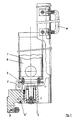
- a helix 9 is provided in the interior of the housing 6, which extends from the inside of the housing only over part of the housing cross section.
- the spiral runs from the open upper to the closed lower housing end and forms a raceway for the round bodies.
- a core 10 extends downward through approximately two spiral turns.
- the angle of inclination of the bushes 1 to the vertical is selectable or adjustable and is expediently between 30 ° and 60 °.
- the slope of the bushings 1 and the slope Angle of the career 9 are chosen so that the parts between the career turns can not get stuck.
- the round bodies successively enter the upper end of the housing 6 at a mutual distance and roll downward on the helical track 9.
- an elevator effect is generated which enables the magazine to be picked up or filled practically without jolts.
- gentle emptying is possible.
- the magazine is stopped and the rotary drive device changes after the bushing has been swung out.
- the dimensions of the magazine are appropriately adapted to the round bodies to be accommodated.
Landscapes
- Engineering & Computer Science (AREA)
- Mechanical Engineering (AREA)
- Filling Or Emptying Of Bunkers, Hoppers, And Tanks (AREA)
- Coating With Molten Metal (AREA)
- Diaphragms For Electromechanical Transducers (AREA)
- Electrical Discharge Machining, Electrochemical Machining, And Combined Machining (AREA)
- Photoreceptors In Electrophotography (AREA)
- Vehicle Step Arrangements And Article Storage (AREA)
Abstract
Description
- Die Erfindung betrifft eine Vorrichtung zum Magazinieren von Kleinteilen, insbesondere Rundkörpern, mit einem geneigt angeordneten, in einem Vorrichtungsgestell drehbar gelagerten zylindrischen Gehäuse, das an seiner oberen Stirnseite eine Öffnung zum Einbringen der Kleinteile aufweist, an seiner unteren Stirnseite geschlossen ist und eine wendelförmige Bahn enthält, die sich im Gehäuseinnenraum von der oberen zur unteren Gehäusestirnseite erstreckt, wobei das Gehäuse durch eine zugeordnete Antriebseinrichtung in Drehung versetzbar ist.
- Bei der Klassierung von Rundkörpern, die eine Oberflächenfeinheit aufweisen, welche die Rundkörper stoßempfindlich macht, z.B. im Falle von Wälzkörpern für Kugellager, müssen die unterschiedlich klassierten Rundkörper zur Lagerung und zum Transport in Magazine eingebracht werden. Bisher wurden die Rundkörper einfach in Aufnahmemagazine fallen oder rollen gelassen, was beim Aufprall der Körper aufeinander zu Oberflächenbeschädigungen und zu Ausschuß führte.
- Aus der DE-AS 1,474.925 ist eine Vorrichtung der einleitend angegebenen Art bekannt, die als Selbstverkäufer für Zuckerwürfel ausgebildet ist. Bei dieser Vorrichtung ist im Gehäuseinneren ein konzentrischer Innenmantel vorgesehen, der mit den Teilen befüllt wird, die über Öffnungen im Innenmantel in den Bereich der an der Außenseite des Innenmantels verlaufenden wendelförmigen Bahn austreten und zur vereinzelten Abgabe zum oberen Gehäuseende wandern. Eine derartige Ausbildung wäre zum Magazinieren von stoßempfindlichen Rundkörpern aus Stahl der vorstehend erläuterten Art völlig ungeeignet, weil die Rundkörper in Schüttgutform in den Innenmantel des Gehäuses gefüllt werden müßten und dabei beschädigt würden. Die bekannte Vorrichtung hätte also die schon erwähnten Nachteile des bisherigen Magazinierens der stoßempfindlichen Rundkörper.
- Die Aufgabe der Erfindung besteht darin, eine Vorrichtung der einleitend angegebenen Art zu schaffen, die sich zum Magazinieren von stoßempfindlichen Rundkörpern eignet und jede Beschädigungsgefahr der Körper hintanhält. Die erfindungsgemäße Vorrichtung zeichnet sich dadurch aus, daß sich die wendelförmige Bahn von der Innenseite des zylindrischen Gehäuses nur über einen Teil des Gehäusequerschnittes nach innen erstreckt, daß sich vom Bereich des oberen Gehäuseendes ein Kern nur durch einige Windungen der wendelförmigen Laufbahn hindurch nach unten erstreckt, und daß das Gehäuse mit seinem unteren Ende auswechselbar in einer mit dem Gehäuse drehfest verbunden, am Vorrichtungsgestell schwenkbar gelagerten Buchse steckt, die aus einer Stellung, in welcher sie mit der Drehantriebseinrichtung in Antriebsverbindung steht, in eine Stellung schwenkbar ist, in welcher sie außer Eingriff mit der Antriebseinrichtung steht.
- Es sei erwähnt, daß aus der DD-PS 206.474 ein Speicher und Förderer für rotationssymmetrische Teile, insbesondere Wälzlagerkörper, bekannt ist, der einer anderen Gattung als die Erfindung angehört und ein wendelförmig gebogenes Rohr aufweist, das über Befestigungsarme mit einem Tragkörper verbunden ist, der die Rotationsachse darstellt, wobei die Rohrenden in die Rotationsachse münden. Der Tragkörper ist drehbar gelagert und mit einem Antrieb gekoppelt.
- Diese Vorrichtung hat aber kein zylindrisches Gehäuse, das eine wendelförmige Bahn enthält. Die bekannte Konstruktion hat vor allem den Nachteil, daß sie nur für rotationssymmetrische Teile einer bestimmten Abmessung geeignet ist und die Gefahr eines Steckenbleibens der Teile besteht. Der Rohrquerschnitt und der Wickeldurchmesser der Wendel müssen genau auf den Teildurchmesser und die Teillänge abgestimmt sein, was bedeutet, daß für nahezu jede Teilabmessung ein eigenes Magazin erforderlich ist. Es können deshalb nur rotationssymmetrische Teile magaziniert werden, Teile mit anderer Form würden das Magazin sofort verstopfen. Probleme macht bei der bekannten Konstruktion auch die erste Krümmung nach dem zentrischen Einlaufrohr, weil sie zu Betriebsstörungen Anlaß geben kann.
- Im Gegensatz zur bekannten Ausführung ermöglicht die erfindungsgemäße Vorrichtung, bei welcher die wendelförmige Bahn gegen das Innere des zylindrischen Gehäuses offen ist, einen großen Freiraum. Durch den kurzen Kern im oberen Wendelbahnabschnitt und die Gehäuseschrägstellung kann bei vorbestimmter Gehäusedrehzahl ein Aufeinanderprallen rasch hintereinander in das Gehäuse fallender Teile absolut vermieden werden. Bei der erfindungsgemäßen Vorrichtung wird jeder Teil aus jeder Rotationsstellung des Gehäuses sofort wegtransportiert. Damit können mit einer hohen Frequenz von z.B. mehr als 8 Teilen pro Sekunde empfindliche Teile schonend magaziniert werden.
- Ein weiterer Vorteil des erfindungsgemäßen Magazins besteht darin, daß es auf einfache Weise auswechselbar ist, um als Lager- und Transportbehälter verwendet zu werden. Ferner hat das erfindungsgemäße Magazin bei gleichem Platzbedarf ein wesentlich höheres Füllvolumen als das bekannte Magazin, dessen Austauschbarkeit in mechanischer Hinsicht wesentlich aufwendiger ist.
- Gemäß einer Weiterbildung der Erfindung weist die Drehantriebseinrichtung eine endlose Kette auf, die mit der Buchse über ein an dieser montiertes Zahnritzel in Eingriff versetzbar ist, wobei eine Mehrzahl von gleichartigen Buchsen zur Aufnahme je eines Magazines nebeneinander angeordnet und mit der Antriebskette kuppelbar sind.
- Gemäß einer bevorzugten Ausführungsform der Erfindung ist der Neigungswinkel der Buchse einstellbar und beträgt vorzugsweise zwischen 30° und 60°.
- Die Erfindung ermöglicht eine stoßfreie Magazinierung der Rundkörper, die in jedes Magazin einzeln eingebracht werden und nacheinander auf der wendelförmigen Laufbahn nach unten rollen, wobei das Magazin entgegen der Wendellaufrichtung gedreht wird. Der Neigungswinkel und die Drehzahl der Magazinaufnahmebuchse sind so gewählt, daß die Rundkörper sich unter dem Elevatoreffekt stoßfrei aneinanderreihen und die Magazine von unten nach oben füllen.
- Ein Ausführungsbeispiel der Erfindung wird nachfolgend unter Bezugnahme auf die Zeichnungen näher erläutert. Es zeigen:
- Fig. 1 eine schematische Ansicht einer Vorrichtung gemäß der Erfindung,
- Fig. 2 einen Teillängsschnitt durch eine Magazinhalterung und
- Fig. 3 einen Längsschnitt durch ein Magazin.
- Die Vorrichtung weist eine Reihe von nebeneinander angeordneten zylindrischen Buchsen 1 auf, von denen in Fig. 1 nur eine gezeigt ist und die je in einem Maschinengestell 2, z.B. dem Gestell einer Klassiervorrichtung für Rundkörper über einen Lagerteil 3 drehbar gelagert sind. Der Lagerteil 3 ist seinerseits am Gestell 2 bei 2′ schwenkbar gelagert (vgl. Fig. 2) und steht über ein am unteren Ende der Buchse 1 montiertes Zahnritzel 4 mit einer nicht gezeigten endlosen Kette einer in Fig. 2 nur schematisch angedeuteten Antriebseinrichtung 5 mit einem Motor 5′ in Drehverbindung. In jede Buchse 1 ist das zylindrische Gehäuse 6 eines Magazins auswechselbar eingesteckt und mit der Buchse über ebenfalls nicht gezeigte Mittel drehfest verbunden. In das offene obere Stirnende des Gehäuses 6 mündet ein Einfüllschnabel 7 od.dgl. für die in das Magazin einzutragenden Rundkörper. Die Buchse 1 ist mittels eines mit dem Lagerteil 3 verbundenen Handgriffes 8 vom Gestell 2 wegschwenkbar, wodurch das Antriebsritzel 4 der Buchse 1 außer Eingriff mit der Antriebseinrichtung 5 kommt.
- Wie Fig. 2 zeigt, ist im Inneren des Gehäuses 6 eine Wendel 9 vorgesehen, die sich von der Gehäuseinnenseite nur über einen Teil des Gehäusequerschnittes erstreckt. Die Wendel verläuft vom offenen oberen zum geschlossenen unteren Gehäuseende und bildet eine Laufbahn für die Rundkörper. Im Bereich des oberen Gehäuseendes erstreckt sich ein Kern 10 durch etwa zwei Wendelwindungen nach unten.
- Der Neigungswinkel der Buchsen 1 zur Vertikalen ist wählbar bzw. einstellbar und beträgt zweckmäßig zwischen 30° und 60°. Die Neigung der Buchsen 1 und der Steigungs winkel der Laufbahn 9 werden so gewählt, daß die Teile zwischen den Laufbahnwindungen nicht stecken bleiben können.
- Im Betrieb der Vorrichtung treten die Rundkörper nacheinander mit gegenseitigem Abstand in das obere Ende des Gehäuses 6 ein und rollen auf der wendelförmigen Laufbahn 9 nach unten. Durch Drehung des Magazins mit Hilfe der Antriebseinrichtung 5 entgegen der Laufrichtung wird ein Elevatoreffekt erzeugt, der eine praktisch stoßfreie Aufnahme bzw. Befüllung des Magazins ermöglicht. Bei Umkehr der Drehrichtung ist demgegenüber eine schonende Entleerung möglich. Nach Erreichen des maximalen Füllstandes wird das Magazin stillgesetzt und nach Ausschwenken der Buchse von der Drehantriebseinrichtung gewechselt.
- Die Abmessungen des Magazins werden zweckmäßig den aufzunehmenden Rundkörpern angepaßt.
Claims (3)
Applications Claiming Priority (2)
| Application Number | Priority Date | Filing Date | Title |
|---|---|---|---|
| AT1320/89 | 1989-05-31 | ||
| AT0132089A AT396442B (de) | 1989-05-31 | 1989-05-31 | Vorrichtung zum magazinieren von kleinteilen |
Publications (2)
| Publication Number | Publication Date |
|---|---|
| EP0401197A1 true EP0401197A1 (de) | 1990-12-05 |
| EP0401197B1 EP0401197B1 (de) | 1993-08-11 |
Family
ID=3511340
Family Applications (1)
| Application Number | Title | Priority Date | Filing Date |
|---|---|---|---|
| EP90890145A Expired - Lifetime EP0401197B1 (de) | 1989-05-31 | 1990-05-11 | Vorrichtung zum Magazinieren von Kleinteilen |
Country Status (3)
| Country | Link |
|---|---|
| EP (1) | EP0401197B1 (de) |
| AT (2) | AT396442B (de) |
| DE (1) | DE59002269D1 (de) |
Cited By (1)
| Publication number | Priority date | Publication date | Assignee | Title |
|---|---|---|---|---|
| DE4340456A1 (de) * | 1993-11-27 | 1995-06-01 | Teves Gmbh Alfred | Portioniereinrichtung für Montageteile |
Citations (3)
| Publication number | Priority date | Publication date | Assignee | Title |
|---|---|---|---|---|
| US1232485A (en) * | 1915-10-28 | 1917-07-10 | David Bloom | Receptacle for an article of food. |
| DD138044A1 (de) * | 1978-07-03 | 1979-10-10 | Hans W Mnilk | Speicher und foerderer fuer rotationssymmetrische teile |
| EP0215516A1 (de) * | 1985-09-02 | 1987-03-25 | Elite N.V. | Kupplungsstück zum Verbinden von aufeinanderfolgenden Teilen einer Förderspirale |
Family Cites Families (1)
| Publication number | Priority date | Publication date | Assignee | Title |
|---|---|---|---|---|
| SU1144840A1 (ru) * | 1982-08-04 | 1985-03-15 | Воронежский Политехнический Институт | Барабанное автоматическое бункерно-загрузочное устройство |
-
1989
- 1989-05-31 AT AT0132089A patent/AT396442B/de not_active IP Right Cessation
-
1990
- 1990-05-11 AT AT90890145T patent/ATE92822T1/de not_active IP Right Cessation
- 1990-05-11 DE DE9090890145T patent/DE59002269D1/de not_active Expired - Fee Related
- 1990-05-11 EP EP90890145A patent/EP0401197B1/de not_active Expired - Lifetime
Patent Citations (3)
| Publication number | Priority date | Publication date | Assignee | Title |
|---|---|---|---|---|
| US1232485A (en) * | 1915-10-28 | 1917-07-10 | David Bloom | Receptacle for an article of food. |
| DD138044A1 (de) * | 1978-07-03 | 1979-10-10 | Hans W Mnilk | Speicher und foerderer fuer rotationssymmetrische teile |
| EP0215516A1 (de) * | 1985-09-02 | 1987-03-25 | Elite N.V. | Kupplungsstück zum Verbinden von aufeinanderfolgenden Teilen einer Förderspirale |
Non-Patent Citations (1)
| Title |
|---|
| SOVIET INVENTIONS ILLUSTRATED,P,Q Sektionen, Woche 8539, 6. November 1985 DERWENT PUBLICATIONS LTD., London, Seite 29, P 56 & SU 1144 840 - A ( VORON POLY ) * |
Cited By (1)
| Publication number | Priority date | Publication date | Assignee | Title |
|---|---|---|---|---|
| DE4340456A1 (de) * | 1993-11-27 | 1995-06-01 | Teves Gmbh Alfred | Portioniereinrichtung für Montageteile |
Also Published As
| Publication number | Publication date |
|---|---|
| AT396442B (de) | 1993-09-27 |
| EP0401197B1 (de) | 1993-08-11 |
| ATE92822T1 (de) | 1993-08-15 |
| DE59002269D1 (de) | 1993-09-16 |
| ATA132089A (de) | 1993-01-15 |
Similar Documents
| Publication | Publication Date | Title |
|---|---|---|
| DE2437193C2 (de) | Vorrichtung zum Vereinzeln und Zählen von Münzen gleicher Wertigkeit | |
| DE1436508C3 (de) | Zufuhrvorrichtung für eine Kapsel markierungsmaschine | |
| DE2801864C2 (de) | Vorrichtung zum Zählen und Ausgeben von Münzen | |
| DE2747866A1 (de) | Vorrichtung zum ausstreuen von saatgut | |
| DE4019104C2 (de) | ||
| EP3552993B1 (de) | Vereinzelungsmaschine | |
| EP0401197B1 (de) | Vorrichtung zum Magazinieren von Kleinteilen | |
| DE3490795C2 (de) | Vorrichtung zum Herausnehmen und Zuf}hren von St}ckg}tern | |
| DE2347143C3 (de) | Vorrichtung zum Bearbeiten von Werkstücken in einer rotierenden Trommel | |
| DE4104716C1 (de) | ||
| EP0241884B1 (de) | Austragevorrichtung für Schüttgut | |
| DE2607265C3 (de) | Vorrichtung zum Kühlen von Gußteilen und Formsand | |
| DE3321173C2 (de) | ||
| EP0695942B1 (de) | Grossraum-Magazin mit Wechselcontainer | |
| DE2649835C3 (de) | Schneckenförderer für körniges Material, wie Getreide | |
| EP1502664A2 (de) | Trennförderer | |
| DE3417498A1 (de) | Speichereinrichtung fuer integrierte schaltkreise | |
| DE1054013B (de) | Senkrechter Schneckenfoerderer | |
| DE1103847B (de) | Schneckenelevator | |
| DE10162598B4 (de) | Vorrichtung zum Transport von kleinstückigen Gegenständen | |
| DE1477963C3 (de) | ||
| DE3208169A1 (de) | Munitionsfoerdervorrichtung | |
| DE2636190A1 (de) | Drehkopfvorrichtung fuer die beschickung der speiseschaechte von maschinen fuer die paketierung von zigaretten | |
| DE1481394C (de) | Vorrichtung zum Zufuhren von einen Schaft und einen Kopf aufweisenden Korpern, insbesondere Spikes fur Kraftfahrzeugreifen | |
| DE4017677A1 (de) | Zusatzvorrichtung fuer eine schleuderstrahlanlage zur entfernung des strahlmittels bei grossen werkstuecken |
Legal Events
| Date | Code | Title | Description |
|---|---|---|---|
| PUAI | Public reference made under article 153(3) epc to a published international application that has entered the european phase |
Free format text: ORIGINAL CODE: 0009012 |
|
| AK | Designated contracting states |
Kind code of ref document: A1 Designated state(s): AT CH DE FR GB LI SE |
|
| EL | Fr: translation of claims filed | ||
| GBC | Gb: translation of claims filed (gb section 78(7)/1977) | ||
| 17P | Request for examination filed |
Effective date: 19910513 |
|
| 17Q | First examination report despatched |
Effective date: 19921026 |
|
| GRAA | (expected) grant |
Free format text: ORIGINAL CODE: 0009210 |
|
| AK | Designated contracting states |
Kind code of ref document: B1 Designated state(s): AT CH DE FR GB LI SE |
|
| PG25 | Lapsed in a contracting state [announced via postgrant information from national office to epo] |
Ref country code: SE Effective date: 19930811 |
|
| REF | Corresponds to: |
Ref document number: 92822 Country of ref document: AT Date of ref document: 19930815 Kind code of ref document: T |
|
| REF | Corresponds to: |
Ref document number: 59002269 Country of ref document: DE Date of ref document: 19930916 |
|
| GBT | Gb: translation of ep patent filed (gb section 77(6)(a)/1977) |
Effective date: 19930916 |
|
| ET | Fr: translation filed | ||
| PLBE | No opposition filed within time limit |
Free format text: ORIGINAL CODE: 0009261 |
|
| STAA | Information on the status of an ep patent application or granted ep patent |
Free format text: STATUS: NO OPPOSITION FILED WITHIN TIME LIMIT |
|
| 26N | No opposition filed | ||
| PGFP | Annual fee paid to national office [announced via postgrant information from national office to epo] |
Ref country code: GB Payment date: 19950501 Year of fee payment: 6 |
|
| PGFP | Annual fee paid to national office [announced via postgrant information from national office to epo] |
Ref country code: AT Payment date: 19950510 Year of fee payment: 6 |
|
| PGFP | Annual fee paid to national office [announced via postgrant information from national office to epo] |
Ref country code: FR Payment date: 19950519 Year of fee payment: 6 |
|
| PGFP | Annual fee paid to national office [announced via postgrant information from national office to epo] |
Ref country code: CH Payment date: 19950529 Year of fee payment: 6 |
|
| PGFP | Annual fee paid to national office [announced via postgrant information from national office to epo] |
Ref country code: DE Payment date: 19950530 Year of fee payment: 6 |
|
| PG25 | Lapsed in a contracting state [announced via postgrant information from national office to epo] |
Ref country code: GB Effective date: 19960511 Ref country code: AT Effective date: 19960511 |
|
| PG25 | Lapsed in a contracting state [announced via postgrant information from national office to epo] |
Ref country code: LI Effective date: 19960531 Ref country code: CH Effective date: 19960531 |
|
| GBPC | Gb: european patent ceased through non-payment of renewal fee |
Effective date: 19960511 |
|
| REG | Reference to a national code |
Ref country code: CH Ref legal event code: PL |
|
| PG25 | Lapsed in a contracting state [announced via postgrant information from national office to epo] |
Ref country code: FR Effective date: 19970131 |
|
| PG25 | Lapsed in a contracting state [announced via postgrant information from national office to epo] |
Ref country code: DE Effective date: 19970201 |
|
| REG | Reference to a national code |
Ref country code: FR Ref legal event code: ST |