EP0401281B1 - Device for intravaginal, barrier-type prevention of conception and infection - Google Patents
Device for intravaginal, barrier-type prevention of conception and infection Download PDFInfo
- Publication number
- EP0401281B1 EP0401281B1 EP89903370A EP89903370A EP0401281B1 EP 0401281 B1 EP0401281 B1 EP 0401281B1 EP 89903370 A EP89903370 A EP 89903370A EP 89903370 A EP89903370 A EP 89903370A EP 0401281 B1 EP0401281 B1 EP 0401281B1
- Authority
- EP
- European Patent Office
- Prior art keywords
- brim
- dome
- barrier
- rim
- vaginal
- Prior art date
- Legal status (The legal status is an assumption and is not a legal conclusion. Google has not performed a legal analysis and makes no representation as to the accuracy of the status listed.)
- Expired - Lifetime
Links
- 208000015181 infectious disease Diseases 0.000 title claims abstract description 12
- 230000002265 prevention Effects 0.000 title claims abstract description 6
- 208000019802 Sexually transmitted disease Diseases 0.000 claims abstract description 7
- 239000012530 fluid Substances 0.000 claims description 11
- 239000000463 material Substances 0.000 claims description 6
- 230000007423 decrease Effects 0.000 claims description 3
- 238000004891 communication Methods 0.000 claims description 2
- 210000003679 cervix uteri Anatomy 0.000 description 28
- 210000001215 vagina Anatomy 0.000 description 23
- 230000004888 barrier function Effects 0.000 description 9
- 210000003484 anatomy Anatomy 0.000 description 7
- 230000007704 transition Effects 0.000 description 7
- 230000035479 physiological effects, processes and functions Effects 0.000 description 5
- 230000000717 retained effect Effects 0.000 description 5
- 210000004291 uterus Anatomy 0.000 description 5
- 238000007789 sealing Methods 0.000 description 4
- 230000004720 fertilization Effects 0.000 description 3
- 230000001568 sexual effect Effects 0.000 description 3
- 208000030507 AIDS Diseases 0.000 description 2
- 230000037007 arousal Effects 0.000 description 2
- 230000008901 benefit Effects 0.000 description 2
- 238000006073 displacement reaction Methods 0.000 description 2
- 238000003780 insertion Methods 0.000 description 2
- 230000037431 insertion Effects 0.000 description 2
- 230000007246 mechanism Effects 0.000 description 2
- 239000000934 spermatocidal agent Substances 0.000 description 2
- 210000001124 body fluid Anatomy 0.000 description 1
- 239000003795 chemical substances by application Substances 0.000 description 1
- 230000001113 coital effect Effects 0.000 description 1
- 229920001971 elastomer Polymers 0.000 description 1
- 230000000423 heterosexual effect Effects 0.000 description 1
- 229920000126 latex Polymers 0.000 description 1
- 239000002184 metal Substances 0.000 description 1
- 244000005700 microbiome Species 0.000 description 1
- 238000012986 modification Methods 0.000 description 1
- 230000004048 modification Effects 0.000 description 1
- 238000000465 moulding Methods 0.000 description 1
- 229940087419 nonoxynol-9 Drugs 0.000 description 1
- 229920004918 nonoxynol-9 Polymers 0.000 description 1
- 230000027758 ovulation cycle Effects 0.000 description 1
- 230000035515 penetration Effects 0.000 description 1
- 239000004033 plastic Substances 0.000 description 1
- 210000003689 pubic bone Anatomy 0.000 description 1
- 230000009467 reduction Effects 0.000 description 1
- 210000000582 semen Anatomy 0.000 description 1
- 230000001150 spermicidal effect Effects 0.000 description 1
- 208000011580 syndromic disease Diseases 0.000 description 1
- FBWNMEQMRUMQSO-UHFFFAOYSA-N tergitol NP-9 Chemical compound CCCCCCCCCC1=CC=C(OCCOCCOCCOCCOCCOCCOCCOCCOCCO)C=C1 FBWNMEQMRUMQSO-UHFFFAOYSA-N 0.000 description 1
Images


Classifications
-
- A—HUMAN NECESSITIES
- A61—MEDICAL OR VETERINARY SCIENCE; HYGIENE
- A61F—FILTERS IMPLANTABLE INTO BLOOD VESSELS; PROSTHESES; DEVICES PROVIDING PATENCY TO, OR PREVENTING COLLAPSING OF, TUBULAR STRUCTURES OF THE BODY, e.g. STENTS; ORTHOPAEDIC, NURSING OR CONTRACEPTIVE DEVICES; FOMENTATION; TREATMENT OR PROTECTION OF EYES OR EARS; BANDAGES, DRESSINGS OR ABSORBENT PADS; FIRST-AID KITS
- A61F6/00—Contraceptive devices; Pessaries; Applicators therefor
- A61F6/06—Contraceptive devices; Pessaries; Applicators therefor for use by females
- A61F6/08—Pessaries, i.e. devices worn in the vagina to support the uterus, remedy a malposition or prevent conception, e.g. combined with devices protecting against contagion
- A61F6/12—Inserters or removers
-
- A—HUMAN NECESSITIES
- A61—MEDICAL OR VETERINARY SCIENCE; HYGIENE
- A61F—FILTERS IMPLANTABLE INTO BLOOD VESSELS; PROSTHESES; DEVICES PROVIDING PATENCY TO, OR PREVENTING COLLAPSING OF, TUBULAR STRUCTURES OF THE BODY, e.g. STENTS; ORTHOPAEDIC, NURSING OR CONTRACEPTIVE DEVICES; FOMENTATION; TREATMENT OR PROTECTION OF EYES OR EARS; BANDAGES, DRESSINGS OR ABSORBENT PADS; FIRST-AID KITS
- A61F6/00—Contraceptive devices; Pessaries; Applicators therefor
- A61F6/06—Contraceptive devices; Pessaries; Applicators therefor for use by females
- A61F6/08—Pessaries, i.e. devices worn in the vagina to support the uterus, remedy a malposition or prevent conception, e.g. combined with devices protecting against contagion
Definitions
- the invention concerns contraception and the prevention of sexually-transmitted diseases by means of a barrier-type device and further concerns a barrier-type device which engages the cervix by extending into the fornices and seals circumferentially against the vagina in the vicinity of the cervix.
- the prior art devices for intravaginal, barrier-type prevention of conception and sexually transmitted disease include the diaphragm and the cervical cap.
- the diaphragm when seated intravaginally, acts as a barrier to prevent sperm from entering the os of the cervix.
- a spermicide is used on the inside of the diaphragm to kill sperm traversing over the edge of the diaphragm.
- the diaphragm is a shallow rubber cup with a rim.
- a round, coiled metal spring is disposed in the rim.
- the diaphragm is intended for intravaginal disposition between the posterior aspect of the pubic bone and the posterior fornix. When thus seated, the diaphragm presses against the vaginal wall to form a continuous barrier therewith.
- the cervical cap is a small, vaulted or domed device, more rigid than the diaphragm, and dimensioned to fit over a cervix, where it is retained by suction, rather than spring tension as is the diaphragm.
- the cap includes a dome which rises from a rim. The cap is slipped over the cervical protrusion to block access to the uterus through the cervical os.
- None of these barrier-type devices is adapted to fit in close anatomical sealing engagement between the vagina and the cervix.
- the diaphragm is held against the upper part of the vaginal canal by the tension of the spring in its rim, while the cervical cap typically engages only the tip of the cervix.
- Both of these devices can be dislodged by sexual arousal, coital activity, or orgasm. As is known, such dislodgment can reduce the effectiveness of the barrier and permit unintended fertilization or unwanted infection, or worse, both.
- DE-845832 shows an example of a cervical cap comprising a dome containing spermicidal material, basal ring around the opening of dome, and circumferential basal crown extending from the basal ring.
- This prior art document forms the basis of the preamble of Claim 1.
- the prior art barrier-type devices form imperfect barriers against the penetration of sperm and agents of sexually transmitted diseases into the uterus.
- fertilization and infection take place within the uterus, therefore the more sound the barrier to the cervical os, the greater the likelihood of preventing such fertilization or infection.
- AIDS immunodeficiency syndrome
- the risk of life-threatening infection accompanying heterosexual activity is increasing steadily. Therefore, there is a compelling need for intravaginal, barrier-type devices which can substantially decrease the risk of infection by significantly increasing the effectiveness and reliability of the barrier to entry of bodily fluids such as semen, into the cervix.
- an intravaginal, barrier-type device which accounts for, and takes advantage of, the anatomy and physiology of the vagina in the vicinity of the cervix to form a more perfect, and a more reliable, seal against the movement of sperm and micro organisms from the vaginal canal through the cervical os into the uterus.
- a significant advantage of such a device is the simultaneous reduction of the prospects of conception.
- the invention is based upon the inventor's critical observation that a barrier-type device engaging the cervix and the vagina by seating at the bottom of the fornices and then folding back from the fornices along the interior vaginal walls provides a barrier adapted to the anatomy and physiology of the vagina in the vicinity of the cervix which not only forms a reliable, effective seal, but also resists displacement during arousal, intercourse, and orgasm.
- the device conforms to and sealingly engages the vagina in the vicinity of the cervix.
- the sealing engagement of the device with the vagina is continuous during all of the expected physiological changes which the vagina and cervix undergo as the result of, for example, sexual activity and menstrual cycle.
- the invention provides a barrier tee device for a barrier-type device for preventing conception and infection by sexually-transmitted diseases, comprising:
- the device includes an annular lip on said rim which extend inwardly from the rim toward a centreline of the dome, and an annular groove being formed by an outward fold of said vaginal brim at said annular lip.
- the invention also provides a kit for intravaginal, barrier-type prevention of conception and sexually-transmitted infection, comprising, in combination:
- the fornical rim of the device forms an inwardly extending lip and a fluid trapping, inwardly extending groove between said brim and said lip.
- the radial distance between said dome and said brim may decrease upwardly with respect to the dome peak and towards the dome opening to a minimum distance just below said rim.
- said fornical rim which is annular and folded, defines fluid trapping means extending radially inwardly of the dome wall, said rim connecting said dome means with said brim means to form a portion of said barrier-type device such that said fluid trapping means is a generally annular groove-shaped cavity in communication with said brim means acting as a scoop and being for trapping fluids entering said brim means acting as a scoop.
- the dome means and said brim means may mutually define an annular passageway between said brim means acting as a scoop and said annular groove-shaped cavity, said passageway having a radial width less than the greatest radial width of said cavity.
- the fluid trapping means preferably extends radially inwardly of said brim means acting as a scoop.
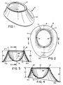
- the device 8 includes a cervical dome 10.
- the dome preferably has a hemi-spherical or hemi-ovoid shape which forms a cervical enclosure.
- the dome 10 transitions to a fornical rim 12, which in turn, transitions by a backward fold to a vaginal brim 14.
- the dome has a peak, or top, 16.
- the vaginal brim circumscribes, or surrounds, the dome and extends upwardly from the rim 12.
- the brim exhibits lateral symmetry, as illustrated in Figure 3, where the lateral extensions 14a and 14b of the brim 14 are substantially equal in form and dimension.
- the width of the brim increases continuously from the anterior to the posterior of the device 8. This increase is revealed in Figures 1 and 4.
- the anterior extension 14c of the brim 14 has a smaller dimension 22 than the dimension 23 at the posterior extension 14d of the brim 14.
- the brim also has an outward bias, or curve, to it, as is seen in Figures 1, 3, and 4.
- the width of the brim increases with circumferential symmetry from an anterior vaginal location 18 on the anterior extension 14c of the brim to a posterior vaginal location 20 on the posterior portion 14d of the brim.
- the circumferential symmetry of the brim 14 is illustrated in Figure 2.
- point A over the lateral extension 14a is displaced in a counterclockwise direction on the rim 12 from the anterior vaginal location by a rim segment equal to the rim segment by which the point B over the lateral extension 14b is displaced on the rim 12 clockwise from the anterior vaginal location 18.
- the dimension 26 reflecting the width of the brim at extension 14a is equal to the dimension 28 reflecting the width of the brim at extension 14b.
- An annular lip 24 is formed in the device 8 by an inward extension of the rim 12 along the periphery of the opening into the dome 10.
- the lip 24 juts into the opening toward the center line 25 of the dome 10.
- the backward fold of the rim 12 at the lip 24 by which the rim 12 transitions to the brim 14 forms an annular groove 27 between the brim 14 and dome 10.
- FIG. 5 and 6 female anatomy is conventionally illustrated as including a cervix 30 through which the cervical os 32 opens to the interior of the uterus 34.
- the vagina 36 includes an inner surface 37 which transitions to the cervix 30 by way of a fornix, an anatomical fold or recess.
- the fornix increases in depth from its anterior to its posterior aspects, which are usually referred to as the anterior fornix 38 and the posterior fornix 39, respectively.
- the vagina 36 transitions, by way of the anterior vaginal wall 40 to the anterior fornix 38, and by way of the posterior vaginal wall 42 to the posterior fornix 39.
- the fornix is laterally symmetrical.
- Figures 5 and 6 illustrate how the barrier-type device of Figures 1-4 is adapted to the anatomy and physiology of the vagina in the vicinity of the cervix.
- the proper orientation of the device 8 finds the cervical dome 10 engaging the cervix, which extends through the opening defined by the rim 12.
- the rim is seated at the bottom of the fornices.
- the annular lip 24 grips the bottom of the cervix at the fornices, thereby forming a circumferential seal.
- the brim 14 extends from the bottom of the fornices in close sealing engagement with the walls of the vagina, thereby continuing the circumferential seal along the vagina forwardly from the fornices.
- the barrier-type device is oriented with respect to the cervix to place the anterior extension 14c against the anterior vaginal wall 40, in the vicinity of the anterior fornix.
- the posterior extension 14d is oriented to engage the posterior vaginal wall 42 in the vicinity of the posterior fornix.
- the orientation of Figure 5 disposes the lateral rim extensions 14a and 14b against the lateral vaginal walls in the vicinity of the lateral fornices.
- a spermicide such as NONOXYNOL-9
- NONOXYNOL-9 is applied to the total surface of the device 8, and the device is inserted into the vagina to engage the cervix with the orientation illustrated in Figures 5 and 6.
- the barrier-type device of the invention will seal from the base of the cervix, in the fornices and continuously and circumferentially along the vagina. This seal is superior to the prior art barrier devices.
- the diaphragm would engage only the posterior fornix, extending across the top of the vaginal wall forward of the anterior of the cervix.
- the cervical cap engages only the top of the cervix, and, generally, does not extend fully into the posterior, anterior, and lateral fornices.
- the device 8 fits precisely to the anatomy and physiology of the vagina in the vicinity of the cervix.
- Such an anatomically adapted form will not only seal effectively when the device is seated, but will also seal reliably by resisting unintentional displacement or dislodgment.
- the device is retained in place by suction exerted in the cervix by the dome 10, by the grip exerted on the base of the cervix by the annular lip 24, by a snug fitting between the rim 12 of the fornices, and by the outward curve of the brim, which flattens against the vagina. All of these mechanisms help prevent dislodgment of the device and contribute to the seal which the device makes.
- the applicator 50 consists of a speculum-type portion with a main body, or a handle, 52 which transitions into a projection 54 having an angle of, preferably, 40° with the main body 52.
- the angled projection 54 has a concave recess 55.
- a rounded forward edge 56 is provided on the distal end of the projection 54.
- a movable inserter 57 is slidably disposed in the main portion 52 and moved in the main portion between a first position, indicated by the solid lines in Figure 7, and a second, release, position denoted in Figure 7 by the interrupted lines.
- the inserter 57 consists of two equivalent elongate pieces 57a and 57b having serrated forward faces 60a and 60b and rear flanges 61a and 61b, respectively.
- the applicator 50 is formed from a physiologically inert material, such as a relatively rigid plastic, and has all of its edges and ends smoothed and rounded to reduce the prospect of injuring the vagina during placement of the device 8.
- Figures 8-10 illustrate how the applicator is used to place the barrier-type device 8.
- the barrier-type device is carried on the applicator by engagement of the forward end 56 in the groove 27 of the device 8 formed between the dome 10, the rim 12, and the posterior vaginal extension 14d.
- the brim 14 is grasped between the serrated surfaces 60a and 60b at the anterior vaginal extension 14c.
- the inserter 57 is retracted to the first position. In this position, the serrated faces 60a and 60b are forced together with the anterior vaginal extension 14c grasped between them.
- the barrier-type device is stretched and retained on the applicator 50 by the tension of the flexible material from which the device 8 is formed.
- the barrier-type device on the applicator 50 is placed intravaginally, with the device oriented as in Figure 5.
- the end 56 of the applicator 50 will place the posterior vaginal extension 14d of the brim against the posterior vaginal wall and seat the rim 12 in the posterior fornix 39.
- the anterior vaginal extension 14c will still be forward of the anterior fornix 38.
- the inserter 57 is slid forwardly in the main body 52 to the second position, which will move the anterior vaginal extension 14c into engagement with the anterior fornix 38.
- the barrier-type device 8 will be retained in the engagement of Figure 5 by the mechanisms described above.
- an extractor 64 has an elongate portion 66 with a cross section substantially flattened in a plane.
- the distal tip of the elongate portion 66 transitions to a hook 68.
- the hook curves backwardly over the elongate portion and is flattened in the same plane.
- An operating handle 69 is attached to the proximal end of the portion 66, to be substantially perpendicular to the plane of flattening of the portion and hooks.
- the barrier-type device 8 is extracted by insertion of the elongate portion 66, hook first, flat into the vagina in the direction of the anterior fornix.
- the extractor is rotated 90, by the handle, to bring the hook 68 into engagement with the back of the brim 12 at the anterior vaginal location.
- the extractor is pulled out, bringing the device 8 with it.
Landscapes
- Health & Medical Sciences (AREA)
- General Health & Medical Sciences (AREA)
- Reproductive Health (AREA)
- Biomedical Technology (AREA)
- Heart & Thoracic Surgery (AREA)
- Vascular Medicine (AREA)
- Life Sciences & Earth Sciences (AREA)
- Engineering & Computer Science (AREA)
- Public Health (AREA)
- Animal Behavior & Ethology (AREA)
- Veterinary Medicine (AREA)
- Orthopedics, Nursing, And Contraception (AREA)
- Surgical Instruments (AREA)
- Prostheses (AREA)
- Eye Examination Apparatus (AREA)
- External Artificial Organs (AREA)
Applications Claiming Priority (3)
| Application Number | Priority Date | Filing Date | Title |
|---|---|---|---|
| US159846 | 1988-02-24 | ||
| US07/159,846 US4858624A (en) | 1988-02-24 | 1988-02-24 | Device and method for intravaginal, barrier-type prevention of conception and infection |
| PCT/US1989/000569 WO1989007919A1 (en) | 1988-02-24 | 1989-02-10 | Device and method for intravaginal, barrier-type prevention of conception and infection |
Publications (3)
| Publication Number | Publication Date |
|---|---|
| EP0401281A1 EP0401281A1 (en) | 1990-12-12 |
| EP0401281A4 EP0401281A4 (en) | 1991-04-17 |
| EP0401281B1 true EP0401281B1 (en) | 1997-11-05 |
Family
ID=22574328
Family Applications (1)
| Application Number | Title | Priority Date | Filing Date |
|---|---|---|---|
| EP89903370A Expired - Lifetime EP0401281B1 (en) | 1988-02-24 | 1989-02-10 | Device for intravaginal, barrier-type prevention of conception and infection |
Country Status (11)
| Country | Link |
|---|---|
| US (1) | US4858624A (da) |
| EP (1) | EP0401281B1 (da) |
| JP (1) | JPH0649047B2 (da) |
| AT (1) | ATE159851T1 (da) |
| AU (1) | AU615727B2 (da) |
| CA (1) | CA1320884C (da) |
| DE (1) | DE68928430T2 (da) |
| DK (1) | DK203890D0 (da) |
| ES (1) | ES2013059A6 (da) |
| GR (1) | GR1001518B (da) |
| WO (1) | WO1989007919A1 (da) |
Families Citing this family (27)
| Publication number | Priority date | Publication date | Assignee | Title |
|---|---|---|---|---|
| US5386836A (en) * | 1986-10-14 | 1995-02-07 | Zedlani Pty Limited | Urinary incontinence device |
| FR2614525B1 (fr) * | 1987-04-29 | 1995-11-10 | Jacques Augros | Tampon en eponge elastique, notamment tampon vaginal |
| US5295984A (en) | 1989-12-07 | 1994-03-22 | Ultrafem, Inc. | Vaginal discharge collection device and intravaginal drug delivery system |
| US6264638B1 (en) | 1989-12-07 | 2001-07-24 | Ultrafem, Inc. | Intravaginal drug delivery system and discharge collection device |
| ES2141162T3 (es) * | 1992-06-30 | 2000-03-16 | Us Health | Metodo para producir materiales de barrera con proteccion contra virus. |
| DK170323B1 (da) * | 1993-03-24 | 1995-08-07 | Tonni Judith Geertsen | Indføringsrør for et vaginalbæger |
| US5846249A (en) * | 1996-02-07 | 1998-12-08 | Pinotage, Llc | Video gynecological examination apparatus |
| US5778886A (en) * | 1996-02-27 | 1998-07-14 | Shihata; Alfred | Vaginal compositions combining a spermicidal agent and a peroxygen compound |
| EP0921826A4 (en) | 1996-07-03 | 2002-07-24 | Ultrafem Inc | METHOD AND SYSTEM FOR PRODUCING ELASTROME ITEMS |
| US5934279A (en) * | 1996-12-04 | 1999-08-10 | Lammers; Delmar R. | Pessary insertion apparatus |
| US5771900A (en) * | 1997-07-22 | 1998-06-30 | Path | Contraceptive diaphragm |
| NL1008170C1 (nl) * | 1998-01-30 | 1999-08-02 | Akzo Nobel Nv | Applicator voor een vaginale ring. |
| US20020058674A1 (en) | 1999-01-08 | 2002-05-16 | Hedenstrom John C. | Systems and methods for treating a mucosal surface |
| FR2788987B1 (fr) | 1999-02-03 | 2001-05-04 | Bernard Chaffringeon | Dispositif a usage unique de transfert d'un liquide actif dans une cavite intracorporelle |
| US6737084B2 (en) | 2000-06-27 | 2004-05-18 | Qualilife | Compositions and methods for enhancing or treating female sexual response |
| US20030153864A1 (en) * | 2001-10-16 | 2003-08-14 | Bernard Chaffringeon | Disposable device and method for transferring an active liquid into a body cavity |
| WO2004075854A2 (en) * | 2003-02-26 | 2004-09-10 | Program For Appropriate Technology In Health | Microbicidal compositions and method of use |
| US20050037033A1 (en) * | 2003-05-23 | 2005-02-17 | Program For Appropriate Technology In Health | Microbicidal compositions and methods and use |
| US8137327B2 (en) * | 2006-06-16 | 2012-03-20 | Family Health International | Vaginal drug delivery system and method |
| US20080121238A1 (en) * | 2006-11-29 | 2008-05-29 | Shihata Alfred A | Kit for Contraception and Prevention of Sexually Transmitted Infections |
| JP2010099440A (ja) * | 2008-10-21 | 2010-05-06 | Yoshio Abe | 女性用安全避妊具。 |
| GB0900461D0 (en) | 2009-01-12 | 2009-02-11 | Photocure Asa | Photodynamic therapy device |
| PT2432410T (pt) * | 2009-05-18 | 2022-04-08 | Intimate Bridge 2 Conception Inc | Inseminação artificial |
| GB201306369D0 (en) | 2013-04-09 | 2013-05-22 | Photocure As | Irradiation device |
| US10226387B2 (en) | 2014-09-19 | 2019-03-12 | Gwynne Marie Hite | Cervical pad |
| US12582559B2 (en) | 2022-03-24 | 2026-03-24 | Outasite, Llc | Bi-directionally positionable tampon |
| EP4477195B1 (de) * | 2023-06-12 | 2026-01-21 | Birgit Arabin | Vaginalpessar |
Family Cites Families (22)
| Publication number | Priority date | Publication date | Assignee | Title |
|---|---|---|---|---|
| FR363976A (fr) * | 1906-03-08 | 1906-08-11 | Georges Pierre Juchaut | Pessaire |
| FR473023A (fr) * | 1914-06-04 | 1914-12-28 | Rene Jean Nicolas Gabriel Vauc | Pessaire |
| US1634555A (en) * | 1925-02-16 | 1927-07-05 | William S Peloubet | Catamenial sack and womb support |
| US2218009A (en) * | 1931-08-10 | 1940-10-15 | Jr William L Schmitz | Introducer |
| US1949863A (en) * | 1932-11-25 | 1934-03-06 | Durex Products Inc | Pessary |
| US2157689A (en) * | 1935-11-02 | 1939-05-09 | Jr Percy L Clark | Pessary |
| US2071248A (en) * | 1935-11-27 | 1937-02-16 | Frank L Campbell | Pessary |
| US2110962A (en) * | 1936-01-30 | 1938-03-15 | Ruth W Munro | Medical device |
| US2104275A (en) * | 1937-05-11 | 1938-01-04 | Schleicher Lawrence | Pessary applicator |
| US2324656A (en) * | 1940-09-03 | 1943-07-20 | Cranston G Vincent | Pessary |
| US2443943A (en) * | 1945-08-28 | 1948-06-22 | Durex Products Inc | Pessary |
| US2664082A (en) * | 1948-03-15 | 1953-12-29 | Walter J Heuboski | Pessary |
| US2625154A (en) * | 1948-06-10 | 1953-01-13 | Durex Products Inc | Laterally collapsible pessary |
| US2638896A (en) * | 1948-07-10 | 1953-05-19 | John T Clark | Spring structure |
| US2676589A (en) * | 1949-12-08 | 1954-04-27 | Walter J Heuboski | Folded pessary |
| DE845832C (de) * | 1950-02-02 | 1952-08-07 | Franz Aichinger Dr Med | Pessar |
| US2823669A (en) * | 1956-07-20 | 1958-02-18 | Holland Rantos Company Inc | Vaginal diaphragm |
| US3128762A (en) * | 1961-08-23 | 1964-04-14 | John C Young | Mechanical contraceptives |
| US3130721A (en) * | 1961-06-26 | 1964-04-28 | John C Young | Mechanical contraceptives |
| US4031886A (en) * | 1975-09-11 | 1977-06-28 | Morhenn Vera B | Occlusive pessary |
| US4286593A (en) * | 1980-05-05 | 1981-09-01 | Place Virgil A | Vaginal contraceptive shield |
| US4381771A (en) * | 1980-07-31 | 1983-05-03 | Kedma, Incorporated | Female contraceptive |
-
1988
- 1988-02-24 US US07/159,846 patent/US4858624A/en not_active Expired - Fee Related
-
1989
- 1989-02-10 WO PCT/US1989/000569 patent/WO1989007919A1/en not_active Ceased
- 1989-02-10 EP EP89903370A patent/EP0401281B1/en not_active Expired - Lifetime
- 1989-02-10 AU AU32018/89A patent/AU615727B2/en not_active Ceased
- 1989-02-10 AT AT89903370T patent/ATE159851T1/de not_active IP Right Cessation
- 1989-02-10 JP JP1502880A patent/JPH0649047B2/ja not_active Expired - Fee Related
- 1989-02-10 DE DE68928430T patent/DE68928430T2/de not_active Expired - Fee Related
- 1989-02-23 CA CA000591867A patent/CA1320884C/en not_active Expired - Fee Related
- 1989-02-23 ES ES8900669A patent/ES2013059A6/es not_active Expired - Lifetime
- 1989-02-23 GR GR890100116A patent/GR1001518B/el not_active IP Right Cessation
-
1990
- 1990-08-24 DK DK203890A patent/DK203890D0/da not_active Application Discontinuation
Also Published As
| Publication number | Publication date |
|---|---|
| WO1989007919A1 (en) | 1989-09-08 |
| AU3201889A (en) | 1989-09-22 |
| US4858624A (en) | 1989-08-22 |
| EP0401281A1 (en) | 1990-12-12 |
| GR1001518B (el) | 1994-02-28 |
| DE68928430T2 (de) | 1999-02-04 |
| ATE159851T1 (de) | 1997-11-15 |
| EP0401281A4 (en) | 1991-04-17 |
| AU615727B2 (en) | 1991-10-10 |
| JPH0649047B2 (ja) | 1994-06-29 |
| DK203890A (da) | 1990-08-24 |
| ES2013059A6 (es) | 1990-04-16 |
| DE68928430D1 (de) | 1997-12-11 |
| JPH03501694A (ja) | 1991-04-18 |
| CA1320884C (en) | 1993-08-03 |
| DK203890D0 (da) | 1990-08-24 |
Similar Documents
| Publication | Publication Date | Title |
|---|---|---|
| EP0401281B1 (en) | Device for intravaginal, barrier-type prevention of conception and infection | |
| US4989618A (en) | Device and method for intravaginal, barrier-type prevention of conception and infection | |
| US5207232A (en) | Device and method for intravaginal, barrier-type prevention of conception and infection | |
| US3683904A (en) | Pessaries | |
| US4004591A (en) | Birth control device | |
| US4703752A (en) | Contraceptive device | |
| US20140109915A1 (en) | Female condom | |
| WO1996016619A1 (en) | Female condom | |
| US5598852A (en) | Receptive condom assembly | |
| US4183358A (en) | Male contraceptive device | |
| US20060278236A1 (en) | Universal unisex safety condom | |
| US10335312B2 (en) | Vaginal ring removal device and methods | |
| US5353811A (en) | Trap | |
| US20140296621A1 (en) | Reproductive infusion device | |
| WO2008067458A2 (en) | A kit for contraception and prevention of sexually transmitted infections | |
| US3842827A (en) | Endocervical contraceptive device | |
| US8764623B2 (en) | Reproductive infusion device | |
| WO2001037766A1 (fr) | Poche contraceptive pour femmes | |
| RU242176U1 (ru) | Пессарий вагинальный | |
| ZA200501858B (en) | Female condom | |
| JP3074835U (ja) | コンドームの改良 | |
| KR20010019454A (ko) | 생리통 치료기 | |
| JP3018562U (ja) | 防病避妊衛生カバー | |
| JPH0650616U (ja) | コンドーム補助器具 |
Legal Events
| Date | Code | Title | Description |
|---|---|---|---|
| PUAI | Public reference made under article 153(3) epc to a published international application that has entered the european phase |
Free format text: ORIGINAL CODE: 0009012 |
|
| 17P | Request for examination filed |
Effective date: 19900904 |
|
| AK | Designated contracting states |
Kind code of ref document: A1 Designated state(s): AT BE CH DE FR GB IT LI LU NL SE |
|
| RIN1 | Information on inventor provided before grant (corrected) |
Inventor name: SHIHATA, ALFRED, A. |
|
| A4 | Supplementary search report drawn up and despatched |
Effective date: 19910301 |
|
| AK | Designated contracting states |
Kind code of ref document: A4 Designated state(s): AT BE CH DE FR GB IT LI LU NL SE |
|
| RAP1 | Party data changed (applicant data changed or rights of an application transferred) |
Owner name: SHIHATA, ALFRED A. |
|
| 17Q | First examination report despatched |
Effective date: 19921117 |
|
| GRAG | Despatch of communication of intention to grant |
Free format text: ORIGINAL CODE: EPIDOS AGRA |
|
| GRAH | Despatch of communication of intention to grant a patent |
Free format text: ORIGINAL CODE: EPIDOS IGRA |
|
| GRAH | Despatch of communication of intention to grant a patent |
Free format text: ORIGINAL CODE: EPIDOS IGRA |
|
| RAP1 | Party data changed (applicant data changed or rights of an application transferred) |
Owner name: HELIX MEDICAL INC. |
|
| RIN1 | Information on inventor provided before grant (corrected) |
Inventor name: SHIHATA, ALFRED A. |
|
| GRAA | (expected) grant |
Free format text: ORIGINAL CODE: 0009210 |
|
| AK | Designated contracting states |
Kind code of ref document: B1 Designated state(s): AT BE CH DE FR GB IT LI LU NL SE |
|
| PG25 | Lapsed in a contracting state [announced via postgrant information from national office to epo] |
Ref country code: IT Free format text: LAPSE BECAUSE OF FAILURE TO SUBMIT A TRANSLATION OF THE DESCRIPTION OR TO PAY THE FEE WITHIN THE PRE;WARNING: LAPSES OF ITALIAN PATENTS WITH EFFECTIVE DATE BEFORE 2007 MAY HAVE OCCURRED AT ANY TIME BEFORE 2007. THE CORRECT EFFECTIVE DATE MAY BE DIFFERENT FROM THE ONE RECORDED.SCRIBED TIME-LIMIT Effective date: 19971105 Ref country code: CH Free format text: LAPSE BECAUSE OF FAILURE TO SUBMIT A TRANSLATION OF THE DESCRIPTION OR TO PAY THE FEE WITHIN THE PRESCRIBED TIME-LIMIT Effective date: 19971105 Ref country code: NL Free format text: LAPSE BECAUSE OF FAILURE TO SUBMIT A TRANSLATION OF THE DESCRIPTION OR TO PAY THE FEE WITHIN THE PRESCRIBED TIME-LIMIT Effective date: 19971105 Ref country code: AT Free format text: LAPSE BECAUSE OF FAILURE TO SUBMIT A TRANSLATION OF THE DESCRIPTION OR TO PAY THE FEE WITHIN THE PRESCRIBED TIME-LIMIT Effective date: 19971105 Ref country code: BE Free format text: LAPSE BECAUSE OF FAILURE TO SUBMIT A TRANSLATION OF THE DESCRIPTION OR TO PAY THE FEE WITHIN THE PRESCRIBED TIME-LIMIT Effective date: 19971105 Ref country code: LI Free format text: LAPSE BECAUSE OF FAILURE TO SUBMIT A TRANSLATION OF THE DESCRIPTION OR TO PAY THE FEE WITHIN THE PRESCRIBED TIME-LIMIT Effective date: 19971105 |
|
| REF | Corresponds to: |
Ref document number: 159851 Country of ref document: AT Date of ref document: 19971115 Kind code of ref document: T |
|
| REG | Reference to a national code |
Ref country code: CH Ref legal event code: EP |
|
| REF | Corresponds to: |
Ref document number: 68928430 Country of ref document: DE Date of ref document: 19971211 |
|
| RAP2 | Party data changed (patent owner data changed or rights of a patent transferred) |
Owner name: SHIHATA, ALFRED A. |
|
| RIN2 | Information on inventor provided after grant (corrected) |
Free format text: SHIHATA, ALFRED A. |
|
| PG25 | Lapsed in a contracting state [announced via postgrant information from national office to epo] |
Ref country code: SE Free format text: LAPSE BECAUSE OF FAILURE TO SUBMIT A TRANSLATION OF THE DESCRIPTION OR TO PAY THE FEE WITHIN THE PRESCRIBED TIME-LIMIT Effective date: 19980205 |
|
| PG25 | Lapsed in a contracting state [announced via postgrant information from national office to epo] |
Ref country code: LU Free format text: LAPSE BECAUSE OF NON-PAYMENT OF DUE FEES Effective date: 19980210 |
|
| NLT2 | Nl: modifications (of names), taken from the european patent patent bulletin |
Owner name: SHIHATA, ALFRED A. |
|
| ET | Fr: translation filed | ||
| NLV1 | Nl: lapsed or annulled due to failure to fulfill the requirements of art. 29p and 29m of the patents act | ||
| REG | Reference to a national code |
Ref country code: CH Ref legal event code: PL |
|
| PLBE | No opposition filed within time limit |
Free format text: ORIGINAL CODE: 0009261 |
|
| STAA | Information on the status of an ep patent application or granted ep patent |
Free format text: STATUS: NO OPPOSITION FILED WITHIN TIME LIMIT |
|
| 26N | No opposition filed | ||
| REG | Reference to a national code |
Ref country code: GB Ref legal event code: IF02 |
|
| PGFP | Annual fee paid to national office [announced via postgrant information from national office to epo] |
Ref country code: FR Payment date: 20020117 Year of fee payment: 14 |
|
| PGFP | Annual fee paid to national office [announced via postgrant information from national office to epo] |
Ref country code: DE Payment date: 20020118 Year of fee payment: 14 |
|
| PG25 | Lapsed in a contracting state [announced via postgrant information from national office to epo] |
Ref country code: DE Free format text: LAPSE BECAUSE OF NON-PAYMENT OF DUE FEES Effective date: 20030902 |
|
| PG25 | Lapsed in a contracting state [announced via postgrant information from national office to epo] |
Ref country code: FR Free format text: LAPSE BECAUSE OF NON-PAYMENT OF DUE FEES Effective date: 20031031 |
|
| REG | Reference to a national code |
Ref country code: FR Ref legal event code: ST |
|
| PGFP | Annual fee paid to national office [announced via postgrant information from national office to epo] |
Ref country code: GB Payment date: 20040204 Year of fee payment: 16 |
|
| PG25 | Lapsed in a contracting state [announced via postgrant information from national office to epo] |
Ref country code: GB Free format text: LAPSE BECAUSE OF NON-PAYMENT OF DUE FEES Effective date: 20050210 |
|
| GBPC | Gb: european patent ceased through non-payment of renewal fee |
Effective date: 20050206 |