EP0401292B1 - Fermeture a charniere pour recipient - Google Patents
Fermeture a charniere pour recipient Download PDFInfo
- Publication number
- EP0401292B1 EP0401292B1 EP89903558A EP89903558A EP0401292B1 EP 0401292 B1 EP0401292 B1 EP 0401292B1 EP 89903558 A EP89903558 A EP 89903558A EP 89903558 A EP89903558 A EP 89903558A EP 0401292 B1 EP0401292 B1 EP 0401292B1
- Authority
- EP
- European Patent Office
- Prior art keywords
- closure member
- bar
- tongue
- container
- latch
- Prior art date
- Legal status (The legal status is an assumption and is not a legal conclusion. Google has not performed a legal analysis and makes no representation as to the accuracy of the status listed.)
- Expired - Lifetime
Links
Images


Classifications
-
- B—PERFORMING OPERATIONS; TRANSPORTING
- B65—CONVEYING; PACKING; STORING; HANDLING THIN OR FILAMENTARY MATERIAL
- B65D—CONTAINERS FOR STORAGE OR TRANSPORT OF ARTICLES OR MATERIALS, e.g. BAGS, BARRELS, BOTTLES, BOXES, CANS, CARTONS, CRATES, DRUMS, JARS, TANKS, HOPPERS, FORWARDING CONTAINERS; ACCESSORIES, CLOSURES, OR FITTINGS THEREFOR; PACKAGING ELEMENTS; PACKAGES
- B65D43/00—Lids or covers for rigid or semi-rigid containers
- B65D43/14—Non-removable lids or covers
- B65D43/16—Non-removable lids or covers hinged for upward or downward movement
- B65D43/163—Non-removable lids or covers hinged for upward or downward movement the container and the lid being made separately
- B65D43/164—Non-removable lids or covers hinged for upward or downward movement the container and the lid being made separately and connected by interfitting hinge elements integrally with the container and the lid formed respectively
-
- E—FIXED CONSTRUCTIONS
- E05—LOCKS; KEYS; WINDOW OR DOOR FITTINGS; SAFES
- E05C—BOLTS OR FASTENING DEVICES FOR WINGS, SPECIALLY FOR DOORS OR WINDOWS
- E05C3/00—Fastening devices with bolts moving pivotally or rotatively
- E05C3/12—Fastening devices with bolts moving pivotally or rotatively with latching action
- E05C3/14—Fastening devices with bolts moving pivotally or rotatively with latching action with operating handle or equivalent member rigid with the latch
-
- E—FIXED CONSTRUCTIONS
- E05—LOCKS; KEYS; WINDOW OR DOOR FITTINGS; SAFES
- E05D—HINGES OR SUSPENSION DEVICES FOR DOORS, WINDOWS OR WINGS
- E05D7/00—Hinges or pivots of special construction
- E05D7/10—Hinges or pivots of special construction to allow easy separation or connection of the parts at the hinge axis
- E05D7/1061—Hinges or pivots of special construction to allow easy separation or connection of the parts at the hinge axis in a radial direction
- E05D7/1077—Hinges or pivots of special construction to allow easy separation or connection of the parts at the hinge axis in a radial direction with snap-fitted pins
-
- E—FIXED CONSTRUCTIONS
- E05—LOCKS; KEYS; WINDOW OR DOOR FITTINGS; SAFES
- E05D—HINGES OR SUSPENSION DEVICES FOR DOORS, WINDOWS OR WINGS
- E05D9/00—Flaps or sleeves specially designed for making from particular material, e.g. hoop-iron, sheet metal, plastics
- E05D9/005—Flaps or sleeves specially designed for making from particular material, e.g. hoop-iron, sheet metal, plastics from plastics
-
- B—PERFORMING OPERATIONS; TRANSPORTING
- B65—CONVEYING; PACKING; STORING; HANDLING THIN OR FILAMENTARY MATERIAL
- B65D—CONTAINERS FOR STORAGE OR TRANSPORT OF ARTICLES OR MATERIALS, e.g. BAGS, BARRELS, BOTTLES, BOXES, CANS, CARTONS, CRATES, DRUMS, JARS, TANKS, HOPPERS, FORWARDING CONTAINERS; ACCESSORIES, CLOSURES, OR FITTINGS THEREFOR; PACKAGING ELEMENTS; PACKAGES
- B65D2251/00—Details relating to container closures
- B65D2251/10—Details of hinged closures
- B65D2251/1016—Means for locking the closure in closed position
-
- B—PERFORMING OPERATIONS; TRANSPORTING
- B65—CONVEYING; PACKING; STORING; HANDLING THIN OR FILAMENTARY MATERIAL
- B65D—CONTAINERS FOR STORAGE OR TRANSPORT OF ARTICLES OR MATERIALS, e.g. BAGS, BARRELS, BOTTLES, BOXES, CANS, CARTONS, CRATES, DRUMS, JARS, TANKS, HOPPERS, FORWARDING CONTAINERS; ACCESSORIES, CLOSURES, OR FITTINGS THEREFOR; PACKAGING ELEMENTS; PACKAGES
- B65D2251/00—Details relating to container closures
- B65D2251/10—Details of hinged closures
- B65D2251/1016—Means for locking the closure in closed position
- B65D2251/1025—Integral locking elements penetrating in an opening, e.g. a flap through a slit, a hook in an opening
-
- E—FIXED CONSTRUCTIONS
- E05—LOCKS; KEYS; WINDOW OR DOOR FITTINGS; SAFES
- E05B—LOCKS; ACCESSORIES THEREFOR; HANDCUFFS
- E05B15/00—Other details of locks; Parts for engagement by bolts of fastening devices
- E05B15/16—Use of special materials for parts of locks
- E05B15/1635—Use of special materials for parts of locks of plastics materials
-
- E—FIXED CONSTRUCTIONS
- E05—LOCKS; KEYS; WINDOW OR DOOR FITTINGS; SAFES
- E05B—LOCKS; ACCESSORIES THEREFOR; HANDCUFFS
- E05B65/00—Locks or fastenings for special use
- E05B65/0014—Locks or fastenings for special use to prevent opening by children
-
- E—FIXED CONSTRUCTIONS
- E05—LOCKS; KEYS; WINDOW OR DOOR FITTINGS; SAFES
- E05D—HINGES OR SUSPENSION DEVICES FOR DOORS, WINDOWS OR WINGS
- E05D5/00—Construction of single parts, e.g. the parts for attachment
- E05D5/10—Pins, sockets or sleeves; Removable pins
- E05D5/14—Construction of sockets or sleeves
- E05D2005/145—Construction of sockets or sleeves with elastically deformable parts
-
- E—FIXED CONSTRUCTIONS
- E05—LOCKS; KEYS; WINDOW OR DOOR FITTINGS; SAFES
- E05Y—INDEXING SCHEME ASSOCIATED WITH SUBCLASSES E05D AND E05F, RELATING TO CONSTRUCTION ELEMENTS, ELECTRIC CONTROL, POWER SUPPLY, POWER SIGNAL OR TRANSMISSION, USER INTERFACES, MOUNTING OR COUPLING, DETAILS, ACCESSORIES, AUXILIARY OPERATIONS NOT OTHERWISE PROVIDED FOR, APPLICATION THEREOF
- E05Y2900/00—Application of doors, windows, wings or fittings thereof
- E05Y2900/10—Application of doors, windows, wings or fittings thereof for buildings or parts thereof
- E05Y2900/13—Type of wing
- E05Y2900/148—Windows
-
- E—FIXED CONSTRUCTIONS
- E05—LOCKS; KEYS; WINDOW OR DOOR FITTINGS; SAFES
- E05Y—INDEXING SCHEME ASSOCIATED WITH SUBCLASSES E05D AND E05F, RELATING TO CONSTRUCTION ELEMENTS, ELECTRIC CONTROL, POWER SUPPLY, POWER SIGNAL OR TRANSMISSION, USER INTERFACES, MOUNTING OR COUPLING, DETAILS, ACCESSORIES, AUXILIARY OPERATIONS NOT OTHERWISE PROVIDED FOR, APPLICATION THEREOF
- E05Y2999/00—Subject-matter not otherwise provided for in this subclass
Definitions
- the present invention relates to child resistant closures for containers having medicinals or other dangerous materials therein and, in particular, to such a container having a bipositional latch which allows adults of limited dexterity to easily open the container in one configuration and which provides a substantial amount of resistance to adolescents in opening the container when in the other configuration.
- a hinge is provided which allows a closure member for the container to be molded separately from the remainder of the container, yet which prevents easy removal of the closure member from the hinge side when the closure member is closed. This allows a separately molded closure member to be easily mated with the container when the closure member is in an open position thereof.
- None of the prior art devices has highly effectively and inexpensively combined a structure which can be configured so that it is easy opening for adults and yet which can be configured so that it is very difficult to open by children.
- closure members for certain types of containers should be designed such that the lid once attached to the body is always maintained connected to the body of the container and preferably such that the lid can be closed using a single hand. That is, that a user can both swing the lid into a closed position while holding the vial with the same hand that is being utilized to swing the lid and that the lid will then automatically lock in a secured configuration when the lid is closed.
- This concept is frequently referred to as "one hand and one motion to close”.
- the container include a hinge for connecting the lid to the body of the container that is also difficult for a child to manipulate and, thereby, open the container from the rear thereof.
- the lid is also a need in the industry for the lid to be able to be removed from the container when in the open configuration thereof such that the lid can be individually molded from the container. This allows one standard size lid to be manufactured for multiple sized containers or vials at a substantial savings in molding expense.
- United States Patent No. 2,797,849 shows a hinge design in which a hinge pintle is connected to two ears molded with the cover. The pintle is forced toward the body of the container in order that the pintle spread the female hinge element "jaws". The pintle passes through the "jaws” and the female elements spring back into place to embrace the pintle and form the hinging structures.
- such a hinge hold the lid in at least one predetermined open position such that the lid will not flop freely back into a closed position, thereby making manipulation of the vial difficult.
- the region between the container lid and body other than at the latch and hinge is preferably also protected from children prying apart the lid from the body in this region.
- the objects of the present invention are: to provide a container having a closure member and a latch for the closure member which is alternatively adjustable to an easy opening configuration or to a child resistant configuration; to provide such a latch that, when in the child resistant configuration thereof, is relatively inaccessible to a child's teeth; to provide such a latch wherein the latch mechanism includes a bipositional and resilient tang or tongue with an outward projecting tooth on a distal end thereof and with an opposite end thereof connected to either the container body or the closure member and with the opposite of the container body or closure member including a bar behind which the tooth flexibly passes upon closing of the closure member such that the tooth is resiliently biased to remain in such position until manipulated by a person opening the container; to provide such a latch wherein the person opening the latch must both push radially against the resiliency of the tongue while pulling upwardly on the closure member thereby requiring simultaneous manipulation of at least three different fungei to open the closure member; to provide such a latch wherein the degree to resistance provided by the latch member to
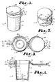
- Fig. 1 is a perspective view of a container having a container body, a closure member, a latch, and a hinge connecting the closure member to the container body.
- Fig. 2 is a fragmentary perspective view of the container, showing the latch in greater detail and the closure member in a closed configuration thereof.
- Fig. 3 is a top plan view of the container showing the closure member thereof in an open configuration.
- Fig. 4 is a cross-sectional view of the container showing the closure member in an open configuration thereof and showing the latch in an easy open configuration thereof, taken along line 4-4 of Fig. 3.
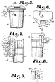
- Fig. 5 is a side elevational view of the container with portions broken away to show detail thereof, with the closure member in the closed configuration thereof and with the latch in the easy open position thereof.
- Fig. 6 is an enlarged and fragmentary top plan view of the container showing the latch thereof.
- Fig. 7 is an enlarged and fragmentary cross-sectional view of the container showing the latch thereof, taken along line 7-7 of Fig. 6.
- Fig. 8 is an enlarged and fragmentary side elevational view of the container showing the hinge thereof, with portions broken away to show detail of the hinge.
- Fig. 9 is a cross-sectional view of the container, taken along line 9-9 of Fig. 5.
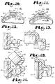
- Fig. 10 is a top plan view of the container body of the container with the closure member removed therefrom, showing a portion of the hinge.
- Fig. 11 is a fragmentary and enlarged bottom plan view of the closure member of the container, showing a portion of the hinge thereof.
- Fig. 12 is an enlarged and fragmentary side and cross-sectional elevational view of the container, showing a portion of the hinge and taken along line 12-12 of Fig. 10.
- Fig. 13 is an enlarged and fragmentary side and cross-sectional elevational view of the closure member of the container, showing a portion of the hinge and taken along line 13-13 of Fig. 11.
- Fig. 14 is an enlarged and fragmentary side elevational view of the container showing the hinge in detail and showing the closure member in an open configuration thereof.
- Fig. 15 is an enlarged and fragmentary cross-sectional side elevation view of the container, showing the hinge and showing the closure member in a closed configuration thereof.
- Fig. 16 is a fragmentary and enlarged front elevational view of the container showing the latch member in a child resistant configuration thereof.
- Fig. 17 is an enlarged and fragmentary front elevational view of the container, showing the latch in an easy open configuration and showing the closure member in a closed configuration thereof.
- Fig. 18 is an enlarged and fragmentary top plan view of the container with the latch in the open configuration thereof.
- Fig. 19 is a fragmentary and enlarged cross-sectional view of the container, showing the closure member in a first open configuration thereof.
- Fig. 20 is a fragmentary and enlarged cross-sectional view of the container, showing the closure member in a second open configuration thereof.
- Fig. 21 is a fragmentary and enlarged cross-sectional view of the container, showing the closure member in a third open configuration thereof.
- Fig. 22 is a fragmentary cross-sectional view of a first modified container showing a closure in a first open configuration thereof.
- Fig. 23 is a fragmentary cross-sectional view of the first modified container, showing the closure in a second open configuration thereof.
- Fig. 24 is a fragmentary cross-sectional view of the first modified container, showing the closure in a third open configuration thereof.
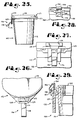
- Fig. 25 is a side elevational view of a third modified container in accordance with the present invention, including a container body, a hinged closure member and a latch wherein lifting tabs offset from the latch are provided on the closure member.
- Fig. 26 is an enlarged and fragmentary top plan view of the third modified container, showing the latch in an easy open configuration thereof.
- Fig. 27 is a fragmentary and enlarged front elevational view of the third modified container, showing the closure member thereof in a closed configuration and showing the latch thereof in a child resistant configuration.
- Fig. 28 is a fragmentary front elevational view of a fourth modified container in accordance with the present invention showing a container body, a closure member, a latch and a tamper indicating device.
- Fig. 29 is an enlarged and fragmentary side elevational view of the fourth modified container with the latch thereof in a child resistant configuration and with the tamper indicating device in position, with portions broken away to show detail thereof.
- Figs. 1 through 21 illustrate a first container in accordance with the present invention, generally designated by the reference numeral 1.
- the container 1 includes a container body 3, a closure member 4, a hinge mechanism 5 rotatably connecting the closure member 4 to the container body 3 and a latch mechanism 6 for securing the closure member 4 in a closed configuration to the container body 3.
- the container body 3 of the illustrated embodiment is a vial-like structure having a generally cylindrical side wall 10 and a bottom wall 11 secured to the side wall 10.
- the side wall 10 is slightly tapered toward the bottom and includes inwardly projecting beads 12 such that multiple container bodies 3 with the closure members thereof in an open position can be stacked together and such that the beads 12 allow the stacked or nested container bodies 3 to be removed from one another, as the beads 12 function to prevent a vacuum from being formed between adjacent container bodies 3.
- the container body 3 could be many different structures such as a squeeze tube, liquid dispensing bottles, including pour and squirt liquid dispensers, aerosol cans, blow molded bottles and the like. It is also foreseen under the present invention that the container body could essentially be only an attachment ring for mounting on a retention ring of a glass bottle, a mechanical structure having a lid, such as a copy machine or the like.
- the present invention can be utilized with a wide variety of devices wherein it is advantageous to protect such a device from being easily opened by children and yet wherein it is desirable for adults of limited dexterity to be able to open the device.
- a first portion 15 of the latch mechanism 6 and a first portion 16 of the hinge mechanism 5 are fixedly attached to the container body 3. Likewise, a second portion 17 of the latch mechanism 6 and a second portion 18 of the hinge mechanism 5 are attached to the closure member 4.
- the latch mechanism first portion 15 comprises a radially outwardly projecting carrier 20 and a tang or tongue 21 which is connected to the carrier at the lower end thereof by a hinge 22.
- the terms “upper”, “lower”, “front”, “back” and the like refer to the direction provided in the description of the drawings and, in particular, "front” is to the left in Fig. 4.
- the distal part of the tongue 21 is thicker or wider than the attached part thereof.
- the distal half of the tongue 21 includes a rectangularly shaped recess 24. The recess 24 opens radially outward when the latch mechanism 6 is in a hard to open configiuration thereof, such as seen in Fig. 7.
- the tongue 21 also has a back surface 26 which is opposite the recess 24 and which is generally planar.
- the carrier 20 includes a mating surface 27 which partly abuts against the tongue back surface 26 when the tongue 21 is in the hard to open configuration thereof.
- the mating surface 27 extends from near the tongue hinge 22 to near the lower edge of the recess 24. As will be discussed later, the extension of the mating surface 27 is important in determining how easy or how hard the latch mechanism 6 is to open.
- the hinge 22 is designed to have limited flexibility, the position of the hinge 32 must be below the top of the mating surface 27 such that the tongue 21 will abut against the surface 27 at full extension of the hinge 22 and provide a backstop for the lower part of the tongue 21, while the tongue upper or distal end 29 is being biased backwards.
- a relatively small elongate channel 28 On the most outward side of the recess 24 is a relatively small elongate channel 28. Also extending from near the recess 24 to near the distal end 29 of the tongue is a slanted cam surface 30. It is noted that the tongue 21 has an easy open configuration which is illustrated in Fig. 5 wherein the tongue 21 is rotated on the hinge 22 such that the back surface 26 does not engage the mating surface 27.
- the tongue 21 is constructed of a relatively resilient but bendable material if sufficient force is applied thereto.
- the tongue 21, when in the hard to open configuration thereof, is bendable at the upper end thereof about an upper edge 32 of the mating surface 27.
- the degree of the radius and the placement of the edge 32 relative to the recess 24 also regulate the degree of difficulty in opening the latch mechanism 6 when in the hard to open configuration.
- the edge 32 is raised and as the degree of radius is lessened, the latch mechanism 6 becomes harder to open because it is harder than to bend the tongue distal end 29 rearward so as to clear the latch mechanism second portion 17 and allow the closure member 4 to be opened.
- the lower side of the recess 24 has associated therewith a bar-like structure 31 that extends across the front of the tongue.
- the structure 31 functions as a lower projection and further limits the ease of opening of the latch mechanism 6.
- the structure 31 prevents a user from simultaneously pushing inward on the tongue 21 and upward on the latch mechanism second portion 17. It is foreseen that the structure 31 may be not included if it is desirable to have an easy open latch of this type, such as on a lunch box.
- the upper end of the tongue 21 is bendable or rotatable to the right with the edge 32 acting as a fulcrum for such bending.
- the mating surface 27 cooperatively prevents a user from depressing the tongue 21 from beneath the recess 24 such that the user must push against the tongue 21 above the recess 24.
- this requires at least two manual operations to be applied to open the container 1 in addition to requiring the container 1 to be held, since a user cannot push upward on the closure member 4 with the same finger or thumb being used to depress the tongue 4.
- the latch mechanism second portion 17 is fixedly secured to the closure member 4 and extends radially outward therefrom.
- the closure member 4 of the illustrated embodiment comprises a cap or lid 33 having a circumferential side wall 34 and a top 35.
- a bottom edge 36 of the wall 34 seats in a corresponding recess 38 in the top of the container body 3.
- the recess 38 has an outer wall or ridge 39 that extends somewhat above the bottom of the closure member 4 when in the closed configuration thereof so as to prevent a child from placing his or her teeth under the closure member 4 and prying it upward.
- This feature could also be provided by providing a reverse draft or a bead and groove mating between the surface of the container body 3 and closure member 4.
- the latch mechanism second portion 17 comprises a wedge or tetrahedral-shaped projection 40 extending outwardly from the closure member 4.
- the projection 40 has an aperture 41 extending from top to bottom therethrough (when in the closed position) and defining an opening for receiving the tongue 21.
- a bar 43 forms the radially outermost side of the aperture 41 and extends between opposite triangularly shaped sections 44 and 45 of the projection 40.
- the aperture 41 is sufficiently wide to receive the distal end of the tongue 21.
- the cam surface 30 of the tongue 21 defining a tooth-like structure engages the lower side of the bar 43, thereby pushing the distal end of the tongue 21 inwardly and bending same backwards over the mating surface 27 until the recess 24 clears the bar 43.
- the distal end of the tongue 21 resiliently springs forward and the recess 24 snugly receives the bar 43 which is essentially shaped identical to the recess 24.
- the bar 43 thereafter interferingly restricts removal of the tongue 21 from the aperture 41 and, in particular, prevents the tongue distal end 29 from passing through the aperture 41 unless the tongue 21 is bent substantially rearward.
- the bar 43 includes a radially outward projecting bead 47 which extends past the tongue 21 and recess 24 thereof. Also in the present embodiment, the bead 47 provides a fingerhold for a user to urge the closure member 4 upwardly when the opposite hand of the user is being utilized to push the upper end of the tongue 21 backwardly so that the bar 43 is free to clear the recess 24. In this manner, the closure member 4 can be opened.
- the bar 43 also has a centrally located and upwardly projecting hemisphere or bump 49 thereon which is positioned so as to interferingly mate with the channel 28 of the tongue 21 when the tongue 21 is in the hard to close configuration thereof and when the closure member 4 is in the closed position thereof, such as is shown in Fig. 7 so as to further interfere with opening of the latch mechanism 6 when in the hard to open configuration thereof. Consequently, the degree of difficulty in opening the latch mechanism 6 depends on many features including the placement of the edge 32, the radius at the top of the surface 27, the flexibility of the tongue 21, the size and placement of the bar-like structure 31 and the interference between the channel 28 and bump 49.
- hinge mechanism first and second portions 16 and 18 and the latch mechanism first and second portions 15 and 17 are shown on the container body 3 and closure member 4 respectively, it is foreseen that their positions could be reversed.
- the hinge mechanism first portion 16 includes a pair of triangularly shaped and outwardly projecting stubs 51 and 52 joined by a bar 53.
- the bar 53 has a circular cross-section and is continuous between the stubs 51 and 52.
- the bar could have other cross-sections including bumps, slots or the like or that the bar could be formed by discontinuous and spaced sections such as nipples extending outwardly from the stubs 51 and 52.
- the bar 53 is positioned close to the top of the container body 3 and is spaced from the container side wall 10 and aligned such that, if the bar 53 were next to the container side wall 10 that same would be tangential thereto.
- a stub wall 55 projects outwardly from the side wall 10 toward the bar 53 and in conjunction with the bar 53 and facing sides of the stubs 51 and 52 define an aperture 56 therebetween.
- the aperture 56 is sized so as to relatively snugly receive a mating portion of the hinge mechanism 6 as will be discussed below.
- the hinge member second portion 18 can best be seen in Figs. 11 and 13.
- the hinge member second portion 18 comprises a semi-circular sleeve 58 sized and shaped to be received on and rotate about the bar 53.
- the sleeve 58 is preferably resilient and has an inner diameter slightly smaller than that of the bar 53 such that the sleeve 58 tightly grips the bar 53.
- the sleeve 58 is supported by a depending wall 59 extending outwardly and downwardly from the rear of the closure member 4. Extending outwardly from the closure member 4 on either side of the depending wall 59 are also a pair of struts 60 and 61 from which also depend a pair of ears 62 and 63 on the inner sides thereof. Between the depending wall 59, the semi-circular sleeve 58 and the ears 63 is defined a centrally located and circular channel 64 sized to be received about the bar 53. A pair of apertures 65 on either side of the sleeve 58 are positioned so as to allow the sleeve 58 to be positioned over the bar 53.
- the sleeve 58 is somewhat resilient and the apertures 65 are readily biased to a more open position during assembly of this structure such that the bar 53 is forced between the apertures 65 and into the channel 64.
- the configuration and geometry of the structure is such that the bar 53 may be placed in or taken from the channel 64 only when the closure member 4 is in an open configuration thereof.
- the stub wall 55 prevents the sleeve 58 moving in such a manner as to allow the bar 53 from becoming unengaged from the channel 64, thus effectively preventing any disassembly of the container 1 by manipulation of the hinge mechanism 5 when the closure member 4 is in a closed configuration thereof.
- Figs 19 through 21 Shown in Figs 19 through 21 are various views of the closure member 4 in different states of opening. It is noted that the position of the stubs 51 and 52 is such that the outer and upper edges 66 or projections therefrom thereof are positioned so as to selectively engage the struts 60 and 61 respectively of the hinge mechanism second portion 18, as can be seen in Fig. 21 (when the closure member 4 is in an open configuration thereof and at a preselected angle relative to the container body 3).
- the edges 66 engage the struts 60 and 61 in such a manner that it requires exertion of a small degree of force on the top of the closure member 4 in order to close the closure member 4 past the position shown in Fig. 21.
- the closure member 4 is held open until the user desires to close it at which time the user, while holding the container 1 in one hand, may use a finger of that hand to push downwardly on the closure member 4 thus pushing the edge 66 past the struts 60 and 61 for a "snap-line" closure. It is noted that this operation requires only the use of a single hand, yet the closure member 4 has at least one stable open position, as is seen in Fig.
- a first modified container 70 that is quite similar to the previous embodiment except in the design of the hinge mechanism 71 thereof.
- the modified container 70 includes a container body 73 and a closure member 74 connected by the hinge mechanism 71.
- the hinge mechanism 71 is in some ways similar to the hinge mechanism 5 of the previous embodiment except that a hexagonal shaped bar 76 extends between supporting struts 77 that extend from the container body 73.
- the closure member 74 includes a depending wall 79 with a semi-circular sleeve 80.
- the interior surface 81 of the sleeve 80 is also hexagonal in shape and similar in size and configuration to the bar 76 so as to be snugly received thereabout.
- the sleeve 80 is sufficiently resilient so as to be rotatable about the bar 76 when pressure is applied to the closure member 74, but when the projections of the bar 76 align with the valleys of the sleeve 80, the sleeve 80 tends to hold that position and, therefore, keep the closure member 74 in such a fixed position until such time as pressure is applied again to the closure member 74 by a user to overcome the resistance to turning thereby provided.
- FIG. 25 through 27 Shown in Figs. 25 through 27 is a third modified embodiment of a container according to the present invention and generally designated by the reference numeral 112.
- the container 112 includes a container body 113 and a lid or closure member 114.
- the container 112 is similar in many respects to the container 1 of a previously described embodiment. Therefore, the major differences between the embodiments will be described in detail rather than repeating many of the common details therebetween.
- the container 112 includes a latch mechanism 116 and a hinge mechanism 117.
- the latch mechanism 116 includes a rotatable tongue or latch member 118 having an easy open position as shown in Fig. 25 and a hard to open position as shown in Fig. 29.
- the latch member 118 when in the hard to open position thereof, has a recess 119 which engages a bar 120 mounted upon the closure member 114, as described in the previously described embodiment.
- the closure member includes a shield 122 extending radially outward from near a tone thereof so as to be spaced from but cover the bar 120 and the latch member 118 when the latch member 118 is in the hard to open position thereof.
- the shield 122 functions to prevent children from using their teeth to bite off the top of the latch member 118 and thereby adds an extra degree of child resistance to the container 112.
- the latch mechanism 116 of the present embodiment also differs from the previous embodiment in that the bar 120 is effectively flush with the most radially exterior surface of the latch member 118 when the latch member 118 is in the hard to open position thereof.
- a further modification of the present embodiment over the first embodiment is in the hinge mechanism 117.
- the hinge mechanism 117 of the present embodiment is otherwise similar to the hinge mechanism of the first embodiment except that a shield 127 is provided to extend over the rearward portion of the hinge mechanism 117.
- the shield 127 provides a smooth exterior surface to a child trying to use their teeth to damage the hinge mechanism 117 and thereby open the container 112. This provides a further degree of child resistance to the container 112.
- Figs. 28 and 29 illustrate a fourth modified container of the present invention generally designated by the reference numeral 130.
- the container 130 includes a body 131 and a closure member 132 which are connected together by latch mechanism 133.
- the container 130 is quite similar to the container 1 of the first embodiment described except that tamper indicating means such as tamper guard 134 is provided.
- the latch mechanism includes a resilient member 135 having an upper tooth 136 which is swingable between easy open and easy to close positions once the container 130 is initially open.
- the closure member 132 has an outwardly extending bar 137 which is manually received by a recess 138 of the resilient member 135.
- the tamper guard 134 is an enclosure which is shaped to fit about the distal portion of the resilient member 135 and, in particular, the tooth 136.
- the tamper guard 134 is frangibly connected to the closure member 132 such that it may be removed by a user prior to use of the container 130.
- the container 130 Prior to removal of the tamper guard 134, the container 130 cannot be opened as the tamper guard 134 interferes with the user's ability to push the tooth 136 backwardly so as to clear the bar 137. Once the tamper guard 134 is broken away, the tooth 136 can be pushed by a user so as to clear the bar 137 at which time the closure member 132 can be raised. It is noted that the operation of pushing the resilient member 135 and raising the closure member 132 must be accomplished simultaneously and normally requires the use of both hands.
Landscapes
- Engineering & Computer Science (AREA)
- Mechanical Engineering (AREA)
- Closures For Containers (AREA)
Abstract
Claims (10)
- Mécanisme de verrouillage pour attacher un élément de fermeture (4) sur un élément conteneur (3), comprenant un verrou à positions multiples (15) raccordé à l'un desdits éléments afin de se déplacer entre une configuration d'ouverture facile et une configuration d'ouverture difficile comportant une languette (21) articulée à une extrémité (22) sur l'un desdits éléments (3) et une dent (30) proche de son extrémité extérieure ou distale, qui s'étend radialement vers l'extérieur depuis sa surface frontale, caractérisé par le fait que la surface postérieure (26) de la languette, dans la cofiguration d'ouverture difficile, vient buter contre une surface appariée (27) qui présente un bord supérieur (32) autour duquel on peut fléchir la languette, et en ce que l'autre desdits éléments (4) présente une barre (43) qui s'étend depuis celui-ci et qui est placée de telle façon que, dans la configuration d'ouverture difficile, la dent (30) est repoussée élastiquement par dessus ladite barre, grâce à quoi il est nécessaire, pour ouvrir le verrou, de fléchir la languette et simultanément de soulever l'élément de fermeture.
- Mécanisme de verrouillage selon la revendication 1, caractérisé par le fait que le bord supérieur (32) de la surface appariée (27) est incurvé, le degré de courbure commandant la difficulté d'ouverture du verrou.
- Mécanisme de verrouillage selon l'une ou l'autre des revendications 1 et 2, caractérisé par le fait que la languette (21) comprend une projection (31) qui s'étend dans la même direction que la dent (30) et qui est de préférence sensiblement en affleurement avec la barre (43) lorsque le verrou est dans sa position fermée, de sorte que l'utilisateur ne peut pas saisir la barre et l'utiliser pour ouvrir l'élément de fermeture.
- Mécanisme de verrouillage selon la revendication 3, caractérisé par le fait qu'il est prévu une projection (44, 45) écartée circonférentiellement de la barre (43) et s'étendant suffisamment vers l'extérieur de telle sorte qu'elle ne peut pas être pressée par un doigt de l'utilisateur pour ouvrir le verrou tandis qu'un autre doigt fait fléchir la dent (30).
- Mécanisme de verrouillage selon l'une quelconque des revendications précédentes, caractérisé par le fait que la barre (43) comporte un bourrelet (49) adapté à s'accoupler avec un canal (28) qui s'étend depuis la surface postérieure (26) vers la dent (30) de la languette (21), et à être dégagé hors dudit canal lorsque le verrou est ouvert.
- Mécanisme de verrouillage selon l'une quelconque des revendications précédentes, caractérisé en ce qu'il est prévu des parois (34, 45) sur les côtés de la languette (21) et à proximité immédiate de celle-ci, de sorte que lorsque le verrou est fermé on ne peut pas introduire facilement les dents d'un enfant entre lesdites parois et ladite languette.
- Mécanisme de verrouillage selon l'une quelconque des revendications précédentes, caractérisé par une bordure circonférentielle (39) qui s'étend autour de l'embouchure de l'élément conteneur (3) et qui est adaptée à s'étendre au-dessus de la surface de fond (36) de l'élément de fermeture (4) lorsque ce dernier est en position fermée de manière à empêcher l'accès à ladite surface de fond pour forcer l'élément de fermeture vers une position ouverte.
- Mécanisme de verrouillage pour attacher un élément de fermeture (4) sur un élément conteneur (3), ledit mécanisme de verrouillage comportant une languette (21) articulée à une extrémité (22) sur l'un desdits éléments (3), et une dent (30) proche de son extrémité extérieure ou distale, s'étendant radialement vers l'extérieur depuis sa surface frontale et comprenant une articulation (16, 18) entre lesdits éléments, caractérisé par le fait que la surface postérieure (26) de la languette, dans une configuration d'ouverture difficile, vient en butée contre une surface appariée (27) qui présente un bord supérieur (32) autour duquel on peut fléchir la languette, et en ce que l'autre desdits éléments (4) comporte une barre (43) qui s'étend depuis celui-ci est qui est placée de telle façon, dans la configuration d'ouverture difficile, que la dent (30) est sollicitée élastiquement par dessus ladite barre, grâce à quoi il est nécessaire, pour ouvrir le verrou, de fléchir la languette et simultanément de soulever l'élément de fermeture, et en ce que l'articulation comprend une barre (53 ou 76) s'étendant entre une paire de tenons (51, 52) s étendant vers l'extérieur depuis l'un desdits éléments (3) et en relation d'écartement vis-à-vis de celui-ci, de manière à constituer une ouverture (56) entre la barre et le corps dudit élément (3), une paroi (59) dépendant de l'autre desdits éléments (4) étant adaptée à s'emboîter intimement à l'intérieur de l'ouverture (56) et comportant un fourreau semi-circulaire (58 ou 80) adapté à recevoir la barre et à pouvoir tourner sur celle-ci, ledit fourreau pouvant être aisément enlevé de la barre lorsque l'élément de fermeture est dans une position ouverte mais non pas lorsque l'élément de fermeture est dans la position fermée, et en outre caractérisé par une projection qui s'étend vers l'extérieur depuis les tenons (51, 52) de façon à engager l'autre élément (4) tandis qu'il est dans une position ouverte, afin de l'empêcher de basculer par gravité vers la position fermée jusqu'à une force soit exercée sur celui-ci par l'utilisateur.
- Mécanisme de verrouillage selon la revendication 8, caractérisé par des parois (51, 52) s'étendant vers l'extérieur depuis l'un des éléments (3) et généralement verticalement alignées et à proximité immédiate du fourreau (58) lorsque l'autre élément (4) est dans la position fermée, de sorte que l'on ne peut pas aisément placer les dents d'un enfant entre lesdites parois et le fourreau, lesdites parois se projetant également de préférence au-dessus de la barre (53), de sorte que l'on ne peut pas aisément placer les dents d'un enfant entre le fourreau et l'élément de fermeture (4).
- Mécanisme de verrouillage selon l'une ou l'autre des revendications 8 et 9, caractérisé par le fait que la barre (76) a une forme polygonale qui réalise des projections sur celle-ci, et en ce que le fourreau semi-circulaire (80) comporte une surface intérieure de forme polygonale avec une série de vallées, ledit fourreau étant adapté à recevoir la barre et à retenir l'élément de fermeture dans une position fixe à chaque emplacement où les projections de la barre sont alignées avec les vallées du fourreau.
Applications Claiming Priority (7)
| Application Number | Priority Date | Filing Date | Title |
|---|---|---|---|
| US160718 | 1988-02-26 | ||
| US07/160,571 US4787526A (en) | 1988-02-26 | 1988-02-26 | Container closure having child protective fastening means |
| US160571 | 1988-02-26 | ||
| US07/160,718 US4809874A (en) | 1988-02-26 | 1988-02-26 | Hinged closure for containers |
| US277228 | 1988-11-11 | ||
| US07/277,228 US4925041A (en) | 1988-02-26 | 1988-11-29 | Closure for container |
| PCT/US1989/000756 WO1989008057A1 (fr) | 1988-02-26 | 1989-02-24 | Fermeture a charniere pour recipient |
Publications (3)
| Publication Number | Publication Date |
|---|---|
| EP0401292A1 EP0401292A1 (fr) | 1990-12-12 |
| EP0401292A4 EP0401292A4 (en) | 1991-03-27 |
| EP0401292B1 true EP0401292B1 (fr) | 1995-04-19 |
Family
ID=27388473
Family Applications (1)
| Application Number | Title | Priority Date | Filing Date |
|---|---|---|---|
| EP89903558A Expired - Lifetime EP0401292B1 (fr) | 1988-02-26 | 1989-02-24 | Fermeture a charniere pour recipient |
Country Status (4)
| Country | Link |
|---|---|
| EP (1) | EP0401292B1 (fr) |
| CA (1) | CA1316844C (fr) |
| DE (1) | DE68922304T2 (fr) |
| WO (1) | WO1989008057A1 (fr) |
Families Citing this family (11)
| Publication number | Priority date | Publication date | Assignee | Title |
|---|---|---|---|---|
| DE9000974U1 (de) * | 1990-01-29 | 1990-05-10 | Robert Thoma GmbH Rotho - Kunststoffwerke, 7800 Freiburg | Haushaltsbox aus Kunststoff |
| NL1000212C2 (nl) * | 1995-04-25 | 1996-10-28 | Dsm Nv | Scharniersysteem. |
| NL1001920C2 (nl) * | 1995-12-18 | 1997-06-19 | Dsm Nv | Doos en daarvoor bestemde verbindingsmiddelen. |
| FR2756261B1 (fr) | 1996-11-22 | 1998-12-31 | Nord Est Dev | Bouchon a charniere, monopiece, pour bouteille a bague faisant office de verseur |
| FR2858301B1 (fr) * | 2003-07-29 | 2006-05-26 | Airsec | Conteneur dessicatif etanche pour le conditionnement de produits sensibles a l'humidite ambiante |
| FR2863968B1 (fr) | 2003-12-19 | 2007-03-02 | Airsec | Dispositif pour l'obturation etanche et le traitement de purification de l'air ambiant de conteneurs de conditionnement pour des produits sensibles a des agents polluants |
| DK2207727T3 (en) | 2007-11-16 | 2016-06-20 | Clariant Production (France) S A S | Container |
| USD597410S1 (en) | 2008-01-29 | 2009-08-04 | Cvs Pharmacy, Inc. | Combined bottle and cap |
| EP2842886B1 (fr) | 2008-10-24 | 2018-09-26 | Clariant Healthcare Packaging (France) S.A.S. | Capuchon vissé, corps de récipient et récipient |
| CN111712437A (zh) * | 2017-11-15 | 2020-09-25 | 波伦齿轮有限责任公司 | 防进入容器和用于处理植物的平台 |
| WO2020035814A1 (fr) * | 2018-08-16 | 2020-02-20 | 科劲市场管理有限公司 | Contenant de stockage doté d'un couvercle |
Citations (1)
| Publication number | Priority date | Publication date | Assignee | Title |
|---|---|---|---|---|
| EP0052990A1 (fr) * | 1980-11-24 | 1982-06-02 | Harold T. Pehr | Capuchon pour récipient d'aérosol |
Family Cites Families (8)
| Publication number | Priority date | Publication date | Assignee | Title |
|---|---|---|---|---|
| US2797840A (en) * | 1954-05-21 | 1957-07-02 | Tri State Plastic Molding Co I | Container, having a hinged cover |
| US3023923A (en) * | 1958-12-04 | 1962-03-06 | Union Carbide Corp | Plastic molded box with novel lid |
| US4219116A (en) * | 1979-02-28 | 1980-08-26 | Pharmacaps, Inc. | Child-resistant container and safety closure therefor |
| US4282983A (en) * | 1980-07-14 | 1981-08-11 | Owens-Illinois, Inc. | Container with improved spring-like hinge |
| GB2082552B (en) * | 1980-08-18 | 1984-06-06 | Johnsen Jorgensen Plastics Ltd | Child resistant container and closure assemblies |
| US4424910A (en) * | 1982-09-07 | 1984-01-10 | Knight Engineering & Molding Co. | Child resistant cap having cap retention and cam surfaces |
| US4687112A (en) * | 1985-08-12 | 1987-08-18 | Owens-Illinois, Inc. | Child-resistant package |
| US4632266A (en) * | 1986-02-24 | 1986-12-30 | Otto Osswald | Container cap |
-
1989
- 1989-02-24 DE DE68922304T patent/DE68922304T2/de not_active Expired - Fee Related
- 1989-02-24 WO PCT/US1989/000756 patent/WO1989008057A1/fr not_active Ceased
- 1989-02-24 EP EP89903558A patent/EP0401292B1/fr not_active Expired - Lifetime
- 1989-02-24 CA CA000591963A patent/CA1316844C/fr not_active Expired - Lifetime
Patent Citations (1)
| Publication number | Priority date | Publication date | Assignee | Title |
|---|---|---|---|---|
| EP0052990A1 (fr) * | 1980-11-24 | 1982-06-02 | Harold T. Pehr | Capuchon pour récipient d'aérosol |
Also Published As
| Publication number | Publication date |
|---|---|
| DE68922304T2 (de) | 1996-01-11 |
| CA1316844C (fr) | 1993-04-27 |
| WO1989008057A1 (fr) | 1989-09-08 |
| DE68922304D1 (de) | 1995-05-24 |
| EP0401292A1 (fr) | 1990-12-12 |
| EP0401292A4 (en) | 1991-03-27 |
Similar Documents
| Publication | Publication Date | Title |
|---|---|---|
| US4809874A (en) | Hinged closure for containers | |
| US4787526A (en) | Container closure having child protective fastening means | |
| US4925041A (en) | Closure for container | |
| US5137260A (en) | Child resistant container with flush latched closure | |
| US8167156B2 (en) | Convertible child-resistant vial | |
| JP2702283B2 (ja) | 潜在的に危険な材料を貯蔵するのに使用される子供に安全なアタッチメント | |
| AU691618B2 (en) | Closure with opening assist feature | |
| US5141129A (en) | Article dispenser with selective child-resistance configuration | |
| US5765705A (en) | Child resistant closure | |
| US6612450B1 (en) | Reversible cap | |
| US6802427B2 (en) | Reversible child resistant closure including two engagable caps | |
| US6202869B1 (en) | Child-resistant/senior-friendly container | |
| US4718567A (en) | Child resistant dispensing closure | |
| US4346809A (en) | Two-piece closure having a child-resistant mode and a non child-resistant mode | |
| EP0289111A2 (fr) | Fermeture dispensatrice résistante aux enfants | |
| JPH024653A (ja) | ヒンジ式小出し密封装置 | |
| US5462181A (en) | Child resistant overcap with safety collar | |
| US4172532A (en) | Closure assembly for a container and a key for opening | |
| EP0541846A1 (fr) | Récipient à l'épreuve des enfants et couvercle basculant pour contenu sec ou liquide | |
| EP0564582A1 (fr) | Capuchon imperdable s'ouvrant avec une cle | |
| CA1316844C (fr) | Fermeture articulee | |
| US5657905A (en) | Child resistant safety cap with collar and semi-flexible tether for sprayers | |
| US5636756A (en) | Childproof closure with means for facilitating authorized removal | |
| US5397008A (en) | Child resistant cap and safety collar ring | |
| GB2082552A (en) | Child resistant container and closure assemblies |
Legal Events
| Date | Code | Title | Description |
|---|---|---|---|
| PUAI | Public reference made under article 153(3) epc to a published international application that has entered the european phase |
Free format text: ORIGINAL CODE: 0009012 |
|
| 17P | Request for examination filed |
Effective date: 19900702 |
|
| AK | Designated contracting states |
Kind code of ref document: A1 Designated state(s): AT BE CH DE FR GB IT LI LU NL SE |
|
| A4 | Supplementary search report drawn up and despatched |
Effective date: 19910205 |
|
| AK | Designated contracting states |
Kind code of ref document: A4 Designated state(s): AT BE CH DE FR GB IT LI LU NL SE |
|
| RBV | Designated contracting states (corrected) |
Designated state(s): BE CH DE FR GB IT LI LU NL |
|
| 17Q | First examination report despatched |
Effective date: 19920305 |
|
| GRAA | (expected) grant |
Free format text: ORIGINAL CODE: 0009210 |
|
| AK | Designated contracting states |
Kind code of ref document: B1 Designated state(s): BE CH DE FR GB IT LI LU NL |
|
| REF | Corresponds to: |
Ref document number: 68922304 Country of ref document: DE Date of ref document: 19950524 |
|
| ITF | It: translation for a ep patent filed | ||
| ET | Fr: translation filed | ||
| BECA | Be: change of holder's address |
Free format text: 950419 *PEHR HAROLD T.:P.O. BOX 6698, LEAWOOD KANSAS 66206 |
|
| PLBE | No opposition filed within time limit |
Free format text: ORIGINAL CODE: 0009261 |
|
| STAA | Information on the status of an ep patent application or granted ep patent |
Free format text: STATUS: NO OPPOSITION FILED WITHIN TIME LIMIT |
|
| PG25 | Lapsed in a contracting state [announced via postgrant information from national office to epo] |
Ref country code: LU Free format text: LAPSE BECAUSE OF NON-PAYMENT OF DUE FEES Effective date: 19960229 |
|
| 26N | No opposition filed | ||
| REG | Reference to a national code |
Ref country code: GB Ref legal event code: IF02 |
|
| PGFP | Annual fee paid to national office [announced via postgrant information from national office to epo] |
Ref country code: FR Payment date: 20020212 Year of fee payment: 14 |
|
| PGFP | Annual fee paid to national office [announced via postgrant information from national office to epo] |
Ref country code: GB Payment date: 20020227 Year of fee payment: 14 |
|
| PGFP | Annual fee paid to national office [announced via postgrant information from national office to epo] |
Ref country code: NL Payment date: 20020228 Year of fee payment: 14 Ref country code: CH Payment date: 20020228 Year of fee payment: 14 |
|
| PGFP | Annual fee paid to national office [announced via postgrant information from national office to epo] |
Ref country code: DE Payment date: 20020314 Year of fee payment: 14 |
|
| PGFP | Annual fee paid to national office [announced via postgrant information from national office to epo] |
Ref country code: BE Payment date: 20020418 Year of fee payment: 14 |
|
| PG25 | Lapsed in a contracting state [announced via postgrant information from national office to epo] |
Ref country code: GB Free format text: LAPSE BECAUSE OF NON-PAYMENT OF DUE FEES Effective date: 20030224 |
|
| PG25 | Lapsed in a contracting state [announced via postgrant information from national office to epo] |
Ref country code: LI Free format text: LAPSE BECAUSE OF NON-PAYMENT OF DUE FEES Effective date: 20030228 Ref country code: CH Free format text: LAPSE BECAUSE OF NON-PAYMENT OF DUE FEES Effective date: 20030228 Ref country code: BE Free format text: LAPSE BECAUSE OF NON-PAYMENT OF DUE FEES Effective date: 20030228 |
|
| PG25 | Lapsed in a contracting state [announced via postgrant information from national office to epo] |
Ref country code: NL Free format text: LAPSE BECAUSE OF NON-PAYMENT OF DUE FEES Effective date: 20030901 |
|
| PG25 | Lapsed in a contracting state [announced via postgrant information from national office to epo] |
Ref country code: DE Free format text: LAPSE BECAUSE OF NON-PAYMENT OF DUE FEES Effective date: 20030902 |
|
| GBPC | Gb: european patent ceased through non-payment of renewal fee | ||
| REG | Reference to a national code |
Ref country code: CH Ref legal event code: PL |
|
| PG25 | Lapsed in a contracting state [announced via postgrant information from national office to epo] |
Ref country code: FR Free format text: LAPSE BECAUSE OF NON-PAYMENT OF DUE FEES Effective date: 20031031 |
|
| NLV4 | Nl: lapsed or anulled due to non-payment of the annual fee |
Effective date: 20030901 |
|
| REG | Reference to a national code |
Ref country code: FR Ref legal event code: ST |
|
| PG25 | Lapsed in a contracting state [announced via postgrant information from national office to epo] |
Ref country code: IT Free format text: LAPSE BECAUSE OF NON-PAYMENT OF DUE FEES;WARNING: LAPSES OF ITALIAN PATENTS WITH EFFECTIVE DATE BEFORE 2007 MAY HAVE OCCURRED AT ANY TIME BEFORE 2007. THE CORRECT EFFECTIVE DATE MAY BE DIFFERENT FROM THE ONE RECORDED. Effective date: 20050224 |