EP0401381A1 - Dispositif d'indication de donnees de derogation - Google Patents
Dispositif d'indication de donnees de derogation Download PDFInfo
- Publication number
- EP0401381A1 EP0401381A1 EP90900322A EP90900322A EP0401381A1 EP 0401381 A1 EP0401381 A1 EP 0401381A1 EP 90900322 A EP90900322 A EP 90900322A EP 90900322 A EP90900322 A EP 90900322A EP 0401381 A1 EP0401381 A1 EP 0401381A1
- Authority
- EP
- European Patent Office
- Prior art keywords
- value
- override
- buzzer
- override value
- ride
- Prior art date
- Legal status (The legal status is an assumption and is not a legal conclusion. Google has not performed a legal analysis and makes no representation as to the accuracy of the status listed.)
- Withdrawn
Links
Images


Classifications
-
- G—PHYSICS
- G05—CONTROLLING; REGULATING
- G05B—CONTROL OR REGULATING SYSTEMS IN GENERAL; FUNCTIONAL ELEMENTS OF SUCH SYSTEMS; MONITORING OR TESTING ARRANGEMENTS FOR SUCH SYSTEMS OR ELEMENTS
- G05B19/00—Program-control systems
- G05B19/02—Program-control systems electric
- G05B19/18—Numerical control [NC], i.e. automatically operating machines, in particular machine tools, e.g. in a manufacturing environment, so as to execute positioning, movement or co-ordinated operations by means of program data in numerical form
-
- G—PHYSICS
- G05—CONTROLLING; REGULATING
- G05B—CONTROL OR REGULATING SYSTEMS IN GENERAL; FUNCTIONAL ELEMENTS OF SUCH SYSTEMS; MONITORING OR TESTING ARRANGEMENTS FOR SUCH SYSTEMS OR ELEMENTS
- G05B19/00—Program-control systems
- G05B19/02—Program-control systems electric
- G05B19/18—Numerical control [NC], i.e. automatically operating machines, in particular machine tools, e.g. in a manufacturing environment, so as to execute positioning, movement or co-ordinated operations by means of program data in numerical form
- G05B19/406—Numerical control [NC], i.e. automatically operating machines, in particular machine tools, e.g. in a manufacturing environment, so as to execute positioning, movement or co-ordinated operations by means of program data in numerical form characterised by monitoring or safety
- G05B19/4063—Monitoring general control system
-
- B—PERFORMING OPERATIONS; TRANSPORTING
- B25—HAND TOOLS; PORTABLE POWER-DRIVEN TOOLS; MANIPULATORS
- B25J—MANIPULATORS; CHAMBERS PROVIDED WITH MANIPULATION DEVICES
- B25J19/00—Accessories fitted to manipulators, e.g. for monitoring, for viewing; Safety devices combined with or specially adapted for use in connection with manipulators
- B25J19/06—Safety devices
- B25J19/061—Safety devices with audible signals
-
- G—PHYSICS
- G05—CONTROLLING; REGULATING
- G05B—CONTROL OR REGULATING SYSTEMS IN GENERAL; FUNCTIONAL ELEMENTS OF SUCH SYSTEMS; MONITORING OR TESTING ARRANGEMENTS FOR SUCH SYSTEMS OR ELEMENTS
- G05B2219/00—Program-control systems
- G05B2219/30—Nc systems
- G05B2219/36—Nc in input of data, input key till input tape
- G05B2219/36529—Warn, alert, notify operator to confirm a preset override value, command
-
- G—PHYSICS
- G05—CONTROLLING; REGULATING
- G05B—CONTROL OR REGULATING SYSTEMS IN GENERAL; FUNCTIONAL ELEMENTS OF SUCH SYSTEMS; MONITORING OR TESTING ARRANGEMENTS FOR SUCH SYSTEMS OR ELEMENTS
- G05B2219/00—Program-control systems
- G05B2219/30—Nc systems
- G05B2219/41—Servomotor, servo controller till figures
- G05B2219/41206—Lookup table, memory with certain relationships
Definitions
- the present invention relates to an override information notifying apparatus which permits an operator securely to recognize a set override value.
- a machine which has an override function such that the operating speed of an operating section assigned by a program is modified by an operator's operation.
- a robot having the override function is designed so that a robot operating section can be automatically operated at a program-assigned operating speed, and can be also manually operated at a speed equivalent to the product of the program-assigned operating speed and an override value set at a suitable value less than 100% by the operator's operation of an override switch, at the time of manual robot operation including giving an instruction to the robot.
- the manual operation work can be safely performed at low speed.
- a set override value is displayed on a CRT screen of a robot control unit or on a display panel disposed in the vicinity of the override switch. Since the operator performs various manipulations during the manual operation, however, he sometimes may fail to identify the set override value. If the set override value is too large, in this case, the manual operation is started without modifying it into a proper value, and the excessiveness of the set override value cannot be noticed until the manual operation is started. In such a case, the robot operating section operates at too high a speed, involving danger.
- the object of the present invention is to provide an override information notifying apparatus which permits an operator securely to recognize a set override value.
- an override information notifying apparatus is mounted on a machine having an operating section which is operable at an operating speed determined in dependence on a set override value, and comprises means for generating intermittent signals with a variable generation period, and means for determining the generation period of the intermittent signals in accordance with the set override value.
- the intermittent signals are generated with the period varying depending on the set override value, so that the operator can securely recognize the set override value, thereby rationalizing the set override value.
- the operating section of the machine can be prevented from operating at an excessive speed, so that the safety of the operation can be ensured.
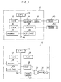
- a robot furnished with an override information notifying apparatus comprises a robot control unit 10 and a teaching pendant 20, and a robot mechanism section 40 and peripheral equipment 50 are connected to the control unit 10.
- the control unit 10 comprises a processor (hereinafter referred to as CPU) 11, a read-only memory (ROM) 12 stored with a control program, a random access memory (RAM) 13 for storing a robot operation program and various data including a set override value, and an axis control section 14.
- the control unit 10 further comprises first and second interfaces 15 and 17 and a manual data input device with CRT display (hereinafter referred to as CRT/MDI) 16, and the peripheral equipment 50 and the teaching pendant 20 are connected to the interfaces 15 and 17, respectively.
- CRT/MDI manual data input device with CRT display
- the teaching pendant 20 comprises a CPU 21, a ROM 22 stored with a program for teaching pendant control, and a RAM 23 for temporarily storing data, including the set override value, and arithmetic results.
- the teaching pendant 20 further comprises an interface 24 connected to the second interface 17 of the control unit 10, a manual data input device with liquid crystal display panel (hereinafter referred to as LCD/MDI) 25, and a one-bit latch circuit (output port) 26, and these elements 22 to 26 are connected to the CPU 21 by means of busses 31.
- the LCD/MDI 25 is provided with an operation key arranged to be operable by an operator for increasing or decreasing the set override value.
- the output terminal of the one-bit latch circuit 26 is connected to one input terminal of an AND gate 28 having another input terminal connected to an oscillator 27, and the output terminal of the AND gate 28 is connected to intermittent signal generating means (buzzer in the present embodiment) 30, formed of a buzzer or a lamp, through an amplifier 29.
- the CPU 21 contains a counter (mentioned later) used for buzzer sounding control.
- the CPU 21 is arranged to reverse the level of binary information stored in the one-bit latch circuit 26 and that of binary information stored in a predetermined region in the RAM 23 and used as an image value corresponding to the binary information in the latch circuit, and to set an initial value in the counter each time the value in the counter is reduced to "0".
- the buzzer 30 sounds in response to the output of the oscillator 27, and when the output level is the low level "0," the sounding is stopped.
- ROM 22 in the teaching pendant 20 is stored with a lookup table TB (Fig. 2) which indicates the correlation between the override value and the sounding period of the buzzer 30.
- the CPU 21 of the teaching pendant 20 executes a buzzer sounding period determining process of Fig. 3 at intervals of a predetermined period TO (msec), e.g., 8 msec.
- Step Sl the CPU 21 executes a process including indication of received data on the liquid crystal display panel of the LCD/MDI 25 (Step S2).
- Step S2 in association with the present invention, the CPU 21 monitors as to whether the operation key of the LCD/MDI 25 is operated by an operator, and transmits the result of the monitoring to the control unit 10.
- the CPU 11 on the side of the control unit 10 updates the set override value stored in the RAM 13, if necessary.
- the CPU 21 compares a new set override value OVN generated by the key operation and a set override value OVR currently stored in the RAM 23, thereby determining whether the override value is modified (Step S3). If there is no modification, the program proceeds to Step S6 mentioned later.
- the set override value is modified before the manual operation, and in this case, the CPU 21 updates the set override value OVR in the RAM 23 to the new value OVN (Step S4).
- the CPU 21 reads out a sounding period T (msec) of the buzzer 30 corresponding to the new set override value OVN from the lookup table TB, and calculates an initial value CO to be set in the counter for sounding control in accordance with the following equation (1), which represents the sounding period T as a function of the predetermined period TO and the initial value CO (Step S5).
- the CPU 21 decrements "1" from the counter value C (initial counter value CO in this case) in the buzzer sounding period determining process for the present period (Step S6), and determines whether the counter value obtained after the decrementing is equal to "0" (Step S7). If the counter value is not "0,” the process for the present period ends. In this case, the individual pieces of binary information in the RAM 23 and the one-bit latch circuit 26 are constant, so that the present state of the buzzer 30, sounding or non-sounding, can be maintained.
- the buzzer 30 sounds in response to the output of the oscillator 27 supplied through the AND gate 28 and the amplifier 29. If the AND gate 28 is disabled when the binary output of the latch circuit 26 is at the low level "0,” on the other hand, the oscillator output is cut off, so that the buzzer 30 does not sound.
- Step S3 If it is concluded in Step S3 that the set override value is not modified, in the meantime, the program immediately proceeds from Step S3 to Step S6. If it is concluded in Step S7 that the counter value C is equal to "0,” the CPU 21 reverses the binary information (image value of the binary information in the one-bit latch circuit 26) in the RAM 23 (Step S8), and then transfers the binary information in the RAM 23 after the level reversal to the one-bit latch circuit 26 (Step S9). As a result, the buzzer 30 is changed from the sounding state to the non-sounding state or reversely. Further, the CPU 21 sets the initial counter value CO in the counter (Step S10), whereupon the process of Fig. 3 for the present period is finished.
- the buzzer 30 sounds during the time the counter value C is reduced from the initial value C0, corresponding to the set override value, to the value "0".
- the override value and the initial counter value CO are set to 70% and 26, respectively.
- the non-sounding state is maintained until the counter value, set to the initial value CO again when sounding is stopped, is reduced to the value "0", e.g., during the period of 200 msec.
- the buzzer 30 intermittently sounds with the period T which corresponds to the set override value (Fig. 4). If the override value and the initial counter value CO are 70% and 26, respectively, for example, the buzzer 30 intermittently sounds with a period of 400 msec. If the override value and the initial counter value CO are 20% and 57, respectively, moreover, the buzzer 30 intermittently sounds with a period of 900 msec.
- the operator fails to identify the set override value displayed on the liquid crystal display panel in the manual operation, he can previously know the set override value and the operating speed of a robot operating section corresponding thereto by hearing a buzzer sound produced before the manual operation is actually started. If it is concluded that the set override value is too large, the set override value displayed on the liquid crystal display panel is modified as required while identifying this set override value, and the manual operation of the robot is started thereafter.
- the present invention is not limited to the embodiment described above, and various changes may be effected therein.
- the intermittent signal generating means is formed of the buzzer 30, which produces audible signals.
- the buzzer 30 may, however, be replaced with a lamp which intermittently produces visible signals.
- the output of the one-bit latch circuit 26 is supplied to the lamp through the amplifier 29 so that the lamp is turned on and off by means of the high- and low- level circuit outputs, respectively.
- the buzzer and the lamp may be used at the same time.
- the initial counter value CO is calculated on the basis of the buzzer sounding period T stored in the lookup table TB and read out in accordance with the override value.
- This embodiment may be modified so that the initial counter value CO is read out in accordance with the override value by the use of the lookup table which indicates the correlation between the initial counter value CO and the override value.
- the buzzer sounding period T (msec) may be calculated according to the following equation (2), which corresponds to the example of setting of Fig. 3, for example, without using the lookup table, such as the table TB, or the initial counter value CO may be calculated according to the following equation (3) so that the fraction of .5 and over is counted as a unit and the rest is cut away.
Landscapes
- Engineering & Computer Science (AREA)
- Human Computer Interaction (AREA)
- Manufacturing & Machinery (AREA)
- Physics & Mathematics (AREA)
- General Physics & Mathematics (AREA)
- Automation & Control Theory (AREA)
- Multimedia (AREA)
- Robotics (AREA)
- Mechanical Engineering (AREA)
- Numerical Control (AREA)
- Manipulator (AREA)
Abstract
Dispositif d'indication de données de dérogation, grâce auquel un opérateur peut confirmer de manière correcte une valeur de dérogation préétablie. Ce dispositif d'indication comporte un pupitre d'apprentissage (20) dans lequel un processeur (21) lit dans une table de consultation en mémoire morte (22) une période de commande d'avertisseur sonore correspondant à la valeur de dérogation préétablie, en fonction de la valeur de dérogation préétablie qui est produite par une unité de commande (10) de robot et qui est enregistrée de manière renouvelable dans une mémoire (23). Le processeur envoie alors à un compteur la valeur initiale calculée en fonction de la période susmentionnée, inverse le niveau d'une sortie binaire d'un circuit de bascule à 1 bit (26) chaque fois que la valeur du compteur, que l'on décrémente périodiquement, atteint ''0'', met l'avertisseur sonore (30) sous tension de manière intermittente avec une période correspondant à la valeur de dérogation préétablie pour indiquer à l'opérateur cette valeur.
Applications Claiming Priority (2)
| Application Number | Priority Date | Filing Date | Title |
|---|---|---|---|
| JP322172/88 | 1988-12-22 | ||
| JP63322172A JPH02167691A (ja) | 1988-12-22 | 1988-12-22 | オーバライド表示方式 |
Publications (2)
| Publication Number | Publication Date |
|---|---|
| EP0401381A1 true EP0401381A1 (fr) | 1990-12-12 |
| EP0401381A4 EP0401381A4 (en) | 1991-05-22 |
Family
ID=18140740
Family Applications (1)
| Application Number | Title | Priority Date | Filing Date |
|---|---|---|---|
| EP19900900322 Withdrawn EP0401381A4 (en) | 1988-12-22 | 1989-12-08 | Over-ride data notifying device |
Country Status (4)
| Country | Link |
|---|---|
| EP (1) | EP0401381A4 (fr) |
| JP (1) | JPH02167691A (fr) |
| KR (1) | KR900702432A (fr) |
| WO (1) | WO1990006837A1 (fr) |
Families Citing this family (2)
| Publication number | Priority date | Publication date | Assignee | Title |
|---|---|---|---|---|
| JP2016107379A (ja) * | 2014-12-08 | 2016-06-20 | ファナック株式会社 | 拡張現実対応ディスプレイを備えたロボットシステム |
| JP7287866B2 (ja) * | 2019-08-30 | 2023-06-06 | ファナック株式会社 | ロボット制御装置およびアーク溶接ロボットシステム |
Family Cites Families (7)
| Publication number | Priority date | Publication date | Assignee | Title |
|---|---|---|---|---|
| DE1058278B (de) * | 1958-06-12 | 1959-05-27 | Gen Mills Inc | Akustischer Greifkraftanzeiger |
| US4305028A (en) * | 1980-04-04 | 1981-12-08 | Nordson Corporation | System for evaluating the capability of a work-performing robot to reproduce a programmed series of motions |
| US4442387A (en) * | 1981-11-25 | 1984-04-10 | Unimation, Inc. | Safe programming system for industrial robots |
| JPS591591U (ja) * | 1982-06-29 | 1984-01-07 | 本田技研工業株式会社 | 産業用ロボツトの安全装置 |
| JP2566550B2 (ja) * | 1984-01-31 | 1996-12-25 | ファナック 株式会社 | ロボツト動作に対するオペレ−タ保護方法 |
| JPS62198909A (ja) * | 1986-02-26 | 1987-09-02 | Atsugi Motor Parts Co Ltd | 産業ロボツトのテイ−チング制御装置 |
| US4765225A (en) * | 1986-08-22 | 1988-08-23 | Birchard William G | Digitally controlled air-over-hydraulic actuator and method |
-
1988
- 1988-12-22 JP JP63322172A patent/JPH02167691A/ja active Pending
-
1989
- 1989-12-08 EP EP19900900322 patent/EP0401381A4/en not_active Withdrawn
- 1989-12-08 WO PCT/JP1989/001236 patent/WO1990006837A1/fr not_active Ceased
-
1990
- 1990-06-07 KR KR1019900701203A patent/KR900702432A/ko not_active Withdrawn
Also Published As
| Publication number | Publication date |
|---|---|
| EP0401381A4 (en) | 1991-05-22 |
| KR900702432A (ko) | 1990-12-07 |
| WO1990006837A1 (fr) | 1990-06-28 |
| JPH02167691A (ja) | 1990-06-28 |
Similar Documents
| Publication | Publication Date | Title |
|---|---|---|
| US4758834A (en) | Pager receiver for giving at least one of extraordinary tones and extraordinary displays | |
| EP0425221B1 (fr) | Dispositif pour commander le chargement de pièces à usiner sur une palette | |
| EP0061839A1 (fr) | Panneau de commande avec appareil de sortie de paroles pour machines-outils à commande numérique | |
| EP0428241B1 (fr) | Procédé et appareil pour le contrôle du mélange de pâte | |
| JP2963299B2 (ja) | プログラマブルコントローラの周辺装置、及び内部情報設定方法 | |
| US5212692A (en) | Help function generation apparatus and method | |
| US4269025A (en) | Electronic alarm timepiece with presettable alarm time memory | |
| JP2716622B2 (ja) | レーザ発振器の制御装置 | |
| JPS63245701A (ja) | 制御装置 | |
| US5504766A (en) | Controller for laser beam oscillator | |
| JPH08278804A (ja) | シーケンス・プログラムの診断方式 | |
| US7612659B2 (en) | Method for intelligent crescendo system | |
| CA1313226C (fr) | Appareil de radiocommunication capable de generer une tonalite commune d'appel sans egard a l'indicatif d'appel d'un signal d'appel | |
| DE68920901T2 (de) | Personenrufvorrichtung mit Nachrichtenanzeigefunktion. | |
| JP2770184B2 (ja) | 放電加工機の制御装置 | |
| KR970001335B1 (ko) | 세탁기의 세탁량 표시/알람 장치 및 그 세탁 자동 제어방법 | |
| WO1990006837A1 (fr) | Dispositif d'indication de donnees de derogation | |
| JP2858207B2 (ja) | 空気調和機の遠隔制御装置 | |
| GB2283116A (en) | Data verification in a process control system | |
| JPH02112004A (ja) | プログラマブルコントローラ | |
| JPH0475853A (ja) | 機械の残り動作時間報知方法及びその装置 | |
| JPS6155702A (ja) | 数値制御装置 | |
| EP0766299A2 (fr) | Amélioration des systèmes de contrÔle | |
| KR0173408B1 (ko) | 통신단말장치의 모래시계기능 구현방법 | |
| KR0178563B1 (ko) | Tv 및 vtr의 시각표시방법 |
Legal Events
| Date | Code | Title | Description |
|---|---|---|---|
| PUAI | Public reference made under article 153(3) epc to a published international application that has entered the european phase |
Free format text: ORIGINAL CODE: 0009012 |
|
| 17P | Request for examination filed |
Effective date: 19900903 |
|
| AK | Designated contracting states |
Kind code of ref document: A1 Designated state(s): DE FR GB |
|
| A4 | Supplementary search report drawn up and despatched |
Effective date: 19910403 |
|
| AK | Designated contracting states |
Kind code of ref document: A4 Designated state(s): DE FR GB |
|
| STAA | Information on the status of an ep patent application or granted ep patent |
Free format text: STATUS: THE APPLICATION IS DEEMED TO BE WITHDRAWN |
|
| 18D | Application deemed to be withdrawn |
Effective date: 19920701 |