EP0401404A1 - Dispositif d'attelage réglable en hauteur - Google Patents
Dispositif d'attelage réglable en hauteur Download PDFInfo
- Publication number
- EP0401404A1 EP0401404A1 EP89110289A EP89110289A EP0401404A1 EP 0401404 A1 EP0401404 A1 EP 0401404A1 EP 89110289 A EP89110289 A EP 89110289A EP 89110289 A EP89110289 A EP 89110289A EP 0401404 A1 EP0401404 A1 EP 0401404A1
- Authority
- EP
- European Patent Office
- Prior art keywords
- bolt
- coupling jaw
- coupling
- jaw carrier
- locking
- Prior art date
- Legal status (The legal status is an assumption and is not a legal conclusion. Google has not performed a legal analysis and makes no representation as to the accuracy of the status listed.)
- Granted
Links
- 230000008878 coupling Effects 0.000 claims abstract description 57
- 238000010168 coupling process Methods 0.000 claims abstract description 57
- 238000005859 coupling reaction Methods 0.000 claims abstract description 57
- 241001236644 Lavinia Species 0.000 abstract 1
- 238000004519 manufacturing process Methods 0.000 description 2
- 238000011161 development Methods 0.000 description 1
- 230000018109 developmental process Effects 0.000 description 1
- 230000009191 jumping Effects 0.000 description 1
- 238000000034 method Methods 0.000 description 1
Images


Classifications
-
- B—PERFORMING OPERATIONS; TRANSPORTING
- B60—VEHICLES IN GENERAL
- B60D—VEHICLE CONNECTIONS
- B60D1/00—Traction couplings; Hitches; Draw-gear; Towing devices
- B60D1/24—Traction couplings; Hitches; Draw-gear; Towing devices characterised by arrangements for particular functions
- B60D1/42—Traction couplings; Hitches; Draw-gear; Towing devices characterised by arrangements for particular functions for being adjustable
- B60D1/46—Traction couplings; Hitches; Draw-gear; Towing devices characterised by arrangements for particular functions for being adjustable vertically
Definitions
- the invention relates to a height-adjustable trailer hitch according to the preamble of claim 1.
- Trailer couplings of this type are known for example from DE-C-29 10 164 and EP-B-0155338.
- great value is placed on the height being adjustable using one-hand operation.
- both bolts are adjusted between their locked position and their unlocked position by means of a single handle.
- the object of the present invention is therefore to create a height-adjustable trailer hitch which is somewhat less convenient to operate than those mentioned at the outset, but which is produced at significantly lower costs can and the risk of accidents of earlier height-adjustable towbars is eliminated.
- the invention makes use of the same basic concept that is also used in the known trailer couplings mentioned at the outset, according to which a coupling jaw, to which the actual coupling is attached, is guided in vertical guide rails attached to the vehicle and can be locked at different heights.
- latches are arranged, which are arranged in horizontal bores in the coupling jaw carrier and are partially adjustable out of the coupling jaw carrier into a locking position or into an unlocking position retracted into it.
- the guide rails are preferably designed so that they absorb the actual tensile force, while the bolts absorb the vertical load.
- the height-adjustable trailer hitch according to the invention requires two-hand operation, ie with one hand the coupling jaw must be held by a handle, while with the other hand the two bolts have to be moved from the locked position to the unlocked position in order for the trailer hitch to be adjusted in height can be.
- the latches can be released from the lock by means of their handling. They are then resiliently biased against the guide rails and grip at further heights hen adjustment of the coupling jaw carrier automatically into the recesses of the guide rails as soon as they are aligned with the next recesses.
- the coupling jaw carrier is shown without the guide rails to be attached to the vehicle.
- the coupling jaw carrier is designed so that it is interchangeable with that described in EP-B 0155338, so that reference can be made to this document with regard to the design and arrangement of the guide rails etc.
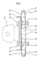
- Fig. 1 shows the coupling jaw carrier 1 in the form of a plate to which the coupling jaw 2 indicated by dash-dotted lines is fastened with the aid of screws and nuts 3 and 4.
- the coupling jaw carrier 1 is provided on both sides with guide surfaces 5 which come into engagement with corresponding guide surfaces of the guide rails mentioned.
- a bolt 7 is slidably guided in two horizontal, preferably aligned blind bores 6. The bolts are in a manner explained in more detail later with the help of levers 8 as a handle from their Ver shown in Fig. 1 locking position, in which they protrude beyond the lateral end faces of the coupling jaw carrier 1, adjustable into an unlocking position in which they are retracted into the coupling jaw carrier.
- a handle 9 in the form of a bracket, on which the coupling jaw carrier can be held comfortably during the height adjustment.
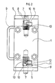
- Fig. 2 shows the front view of the coupling jaw carrier.
- the bolt 7 on the left side is shown in the locking position, while the bolt 7 on the right side is shown in dash-dot lines in a ready position and extended in the unlocking position.
- the standby position is the one where the end face of the bolt is almost flush with the side end face of the coupling jaw carrier.
- Fig. 3 shows the arrangement in the side sectional view with the three possible positions of the lever 8, namely the locking position corresponding to the left in Fig. 2, the unlocking position corresponding to the extended position on the right in Fig. 2 and the standby position according to the dash-dotted representation on the right in Fig. 2nd
- the coupling jaw support is provided with an opening 10 in the area of both bolts 7, within which bolt 7 is exposed. This breakthrough is located approximately in the middle part of the bore receiving the bolt, so that there is enough material on both sides for guiding and supporting the respective bolt 7.
- the lever 8 is inserted into a radial bore in the bolt 7 stuck and anchored in a suitable manner, e.g. B. caulked or screwed.
- a locking plate 11 is attached to the coupling jaw in such a way that it projects into the opening 10.
- the locking plate 11 is provided on its side facing the center of the coupling carrier with a recess 12 forming a step.
- the locking plate 11 is seen in the axial direction of the bolt, at a distance from the outer edge of the opening 10, which is slightly larger than the diameter of the lever 8, so that this in the locking position of the bolt 7 between the outer edge of the opening 10 and the outwardly facing side of the locking plate 11 can be pivoted down (see also Fig. 3).
- the bolt 7 is secured by positive locking via its lever 8 and the locking plate 11.
- a torsion spring 13 is supported on the one hand on the inner wall of the opening 10 and on the other hand on the lever 8.
- the torsion spring 13 on the one hand biases the bolt 8 into the locking position and also exerts a torque on the bolt 7 which tries to pivot it in such a direction that the lever 8 assumes the lowest positions shown in FIG. 3. This torque holds the lever 8 securely in the locking position shown on the left in FIG. 2 between the edge of the opening 10 and the facing side of the locking plate 11.
- both bolts 7 are in their locking position and thus hold the trailer coupling in the guide rails at a certain height. If this altitude is to be changed, the coupling jaw carrier must be gripped on the handle 9. To the friction to reduce between the guide rails and the bolts 7 and thereby facilitate the movement of the bolts 7 into the unlocking position, the coupling jaw carrier 1 should be raised somewhat with the aid of the handle 9.
- the second bolt does not necessarily have to be locked in the unlocked position. Rather, after the engagement of this second bolt with the corresponding recess in the guide rail has been released, while the bolt 7 and lever 8 are in an intermediate position, ie in a position, the coupling jaw carrier can be raised or lowered and the lever 8 can be released again immediately will.
- the unlocked bolt 7 is then pressed by the spring 13 against the end face of the corresponding guide rail and automatically engages in the next following recess of the guide rail when the coupling jaw carrier is raised or lowered further.
- the torsion spring 13 ensures this not only for the latch 7 to automatically snap into the recess, but also for the fact that it is pivoted in its locking position in such a way that the lever 8 again reaches the positive locking position between the edge of the opening 10 and the locking plate 11.
- the opening 10 penetrates the coupling jaw 1 completely, as can be seen in particular in FIG. 3.
- An opening to the rear (right in Fig. 3) is not absolutely necessary, so that instead of the opening, a recess could serve the desired purpose, which extends from the front of the coupling jaw carrier 1 over part of its depth.
- the handle 9 has so far been assumed to be rigidly attached to the top of the coupling jaw carrier 1. It could also be designed to be pivotable and, as long as it is not required, can be pivoted into a position in which it does not protrude, or only slightly, beyond the upper edge of the coupling jaw carrier.
- the length of the opening 10 is greater by approximately the length of the compressed spring 13 than the adjustment stroke of the bolt 7, so that the spring 13 has space within the opening 10 and can be easily installed.
- its end facing away from the lever 8 is supported on the bottom of the opening 10.
- a locking plate 11 formed in one piece with the coupling jaw 1 can equally serve the intended purpose, as the locking plate 11 described separately attached to the coupling jaw.
- the plate forming the actual coupling jaw carrier 1 is formed as a part with both the locking plates 11 'and the mounting bearing 2a of the coupling can.
Landscapes
- Engineering & Computer Science (AREA)
- Transportation (AREA)
- Mechanical Engineering (AREA)
- Fittings On The Vehicle Exterior For Carrying Loads, And Devices For Holding Or Mounting Articles (AREA)
- Agricultural Machines (AREA)
- Vehicle Body Suspensions (AREA)
Priority Applications (4)
| Application Number | Priority Date | Filing Date | Title |
|---|---|---|---|
| AT89110289T ATE85005T1 (de) | 1989-06-07 | 1989-06-07 | Hoehenverstellbare anhaengerkupplung. |
| EP89110289A EP0401404B1 (fr) | 1989-06-07 | 1989-06-07 | Dispositif d'attelage réglable en hauteur |
| DE8989110289T DE58903413D1 (de) | 1989-06-07 | 1989-06-07 | Hoehenverstellbare anhaengerkupplung. |
| ES198989110289T ES2037331T3 (es) | 1989-06-07 | 1989-06-07 | Acoplamiento ajustable en altura para remolque. |
Applications Claiming Priority (1)
| Application Number | Priority Date | Filing Date | Title |
|---|---|---|---|
| EP89110289A EP0401404B1 (fr) | 1989-06-07 | 1989-06-07 | Dispositif d'attelage réglable en hauteur |
Publications (2)
| Publication Number | Publication Date |
|---|---|
| EP0401404A1 true EP0401404A1 (fr) | 1990-12-12 |
| EP0401404B1 EP0401404B1 (fr) | 1993-01-27 |
Family
ID=8201472
Family Applications (1)
| Application Number | Title | Priority Date | Filing Date |
|---|---|---|---|
| EP89110289A Expired - Lifetime EP0401404B1 (fr) | 1989-06-07 | 1989-06-07 | Dispositif d'attelage réglable en hauteur |
Country Status (4)
| Country | Link |
|---|---|
| EP (1) | EP0401404B1 (fr) |
| AT (1) | ATE85005T1 (fr) |
| DE (1) | DE58903413D1 (fr) |
| ES (1) | ES2037331T3 (fr) |
Cited By (4)
| Publication number | Priority date | Publication date | Assignee | Title |
|---|---|---|---|---|
| DE4222342A1 (de) * | 1992-07-08 | 1994-01-13 | Hans Sauermann | Vorrichtung zum Halten einer Anhänge-Kupplungs-Tragplatte |
| EP0843956A1 (fr) * | 1996-11-15 | 1998-05-27 | Costruzioni Meccaniche G. Grassi di Luigi Grassi & C. S.n.c. | Dispositif d'accouplement pour tracteur ou similaire |
| EP2527170A1 (fr) | 2011-05-26 | 2012-11-28 | Rheinmetall MAN Military Vehicles GmbH | Attelage réglable en hauteur, en particulier pour véhicules utilitaires |
| EP2524822A3 (fr) * | 2011-05-20 | 2014-11-05 | Hans Sauermann | Attelage réglable en hauteur |
Citations (4)
| Publication number | Priority date | Publication date | Assignee | Title |
|---|---|---|---|---|
| DE2910164A1 (de) * | 1979-03-15 | 1980-09-25 | Fendt & Co Xaver | Anhaengerkupplung |
| EP0155338A1 (fr) * | 1984-03-28 | 1985-09-25 | ROCKINGER Spezialfabrik für Anhängerkupplungen GmbH & Co. | Attelage à hauteur réglable pour remorque |
| EP0215443A2 (fr) * | 1985-09-17 | 1987-03-25 | Deere & Company | Cadre de support pour un attelage de remorque |
| EP0279082A1 (fr) * | 1987-02-18 | 1988-08-24 | Brink B.V. | Crochet d'attelage |
-
1989
- 1989-06-07 DE DE8989110289T patent/DE58903413D1/de not_active Expired - Fee Related
- 1989-06-07 ES ES198989110289T patent/ES2037331T3/es not_active Expired - Lifetime
- 1989-06-07 EP EP89110289A patent/EP0401404B1/fr not_active Expired - Lifetime
- 1989-06-07 AT AT89110289T patent/ATE85005T1/de not_active IP Right Cessation
Patent Citations (4)
| Publication number | Priority date | Publication date | Assignee | Title |
|---|---|---|---|---|
| DE2910164A1 (de) * | 1979-03-15 | 1980-09-25 | Fendt & Co Xaver | Anhaengerkupplung |
| EP0155338A1 (fr) * | 1984-03-28 | 1985-09-25 | ROCKINGER Spezialfabrik für Anhängerkupplungen GmbH & Co. | Attelage à hauteur réglable pour remorque |
| EP0215443A2 (fr) * | 1985-09-17 | 1987-03-25 | Deere & Company | Cadre de support pour un attelage de remorque |
| EP0279082A1 (fr) * | 1987-02-18 | 1988-08-24 | Brink B.V. | Crochet d'attelage |
Cited By (6)
| Publication number | Priority date | Publication date | Assignee | Title |
|---|---|---|---|---|
| DE4222342A1 (de) * | 1992-07-08 | 1994-01-13 | Hans Sauermann | Vorrichtung zum Halten einer Anhänge-Kupplungs-Tragplatte |
| DE4222342C2 (de) * | 1992-07-08 | 1998-02-19 | Hans Sauermann | Vorrichtung zum Halten einer Anhänge-Kupplungs-Tragplatte |
| EP0843956A1 (fr) * | 1996-11-15 | 1998-05-27 | Costruzioni Meccaniche G. Grassi di Luigi Grassi & C. S.n.c. | Dispositif d'accouplement pour tracteur ou similaire |
| EP2524822A3 (fr) * | 2011-05-20 | 2014-11-05 | Hans Sauermann | Attelage réglable en hauteur |
| EP2527170A1 (fr) | 2011-05-26 | 2012-11-28 | Rheinmetall MAN Military Vehicles GmbH | Attelage réglable en hauteur, en particulier pour véhicules utilitaires |
| EP2527169A1 (fr) | 2011-05-26 | 2012-11-28 | Rheinmetall MAN Military Vehicles GmbH | Attelage réglable en hauteur, notamment pour véhicules utilitaires |
Also Published As
| Publication number | Publication date |
|---|---|
| ATE85005T1 (de) | 1993-02-15 |
| ES2037331T3 (es) | 1993-06-16 |
| DE58903413D1 (de) | 1993-03-11 |
| EP0401404B1 (fr) | 1993-01-27 |
Similar Documents
| Publication | Publication Date | Title |
|---|---|---|
| DE69518155T2 (de) | Greifvorrichtung für behälter | |
| DE69204867T2 (de) | Ausziehbarer Überrollbügel mit Gewichtsausgleich für Schlepper. | |
| DE2910164C2 (de) | Höhenverstellbare Anhängerkupplung | |
| DE19538988A1 (de) | Tischüberbrückungsvorrichtung | |
| DE2947391A1 (de) | Vorrichtung zur verstellung eines sicherheitsgurt-verankerungspunktes | |
| EP1433628B1 (fr) | Attelage de remorque de tracteur agricole | |
| DE4127933C2 (fr) | ||
| EP0401404B1 (fr) | Dispositif d'attelage réglable en hauteur | |
| EP3860401B1 (fr) | Dispositif de fixation pour fixer de manière détachable un panneau de façade sur un tiroir | |
| EP0095443A1 (fr) | Dispositif d'attelage | |
| EP0934848A2 (fr) | Mécanisme de verrouillage pour véhicules porte-conteneurs | |
| EP0047961A1 (fr) | Accouplement de rotule d'attelage pour véhicules moteur | |
| EP1477365B1 (fr) | Dispositif de fixation pour un coffre de toit | |
| DE102004033886B4 (de) | Halteanordnung für Container | |
| DE102020212967B3 (de) | Verriegelungseinrichtung, höhenverstellbarer Tisch mit der Verriegelungseinrichtung, Fahrzeug mit dem höhenverstellbaren Tisch und Verfahren zum Verriegeln des höhenverstellbaren Tischs | |
| EP0492035A1 (fr) | Attelage de remorque, en particulier pour véhicules automobiles | |
| DE2736222A1 (de) | Hubfangverschluss | |
| EP0752328B1 (fr) | Attelage de remorque | |
| AT390034B (de) | Anhaengevorrichtung fuer zugfahrzeuge, insbesondere traktoren | |
| EP1782972A1 (fr) | Attelage de remorque pour un véhicule tracteur, notamment pour un tracteur agricole | |
| DE2837582C2 (de) | Arretiervorrichtung für ein verschwenkbares Element, insbesondere für Tragarme einer Hebebühne für Kraftfahrzeuge | |
| AT525757B1 (de) | Verriegelungsvorrichtung für eine verlagerbare Bunkerwand | |
| DE2829193C2 (de) | Verriegelungsvorrichtung für ein Ballastgewicht eines Schleppers | |
| DE3830424A1 (de) | Zusatzvorrichtung fuer ein zugfahrzeug, insbesondere einen gelaendewagen | |
| DE3412935A1 (de) | Vorrichtung zur sicherung eines mittels betaetigungsgurt bedienbaren rolladens |
Legal Events
| Date | Code | Title | Description |
|---|---|---|---|
| PUAI | Public reference made under article 153(3) epc to a published international application that has entered the european phase |
Free format text: ORIGINAL CODE: 0009012 |
|
| 17P | Request for examination filed |
Effective date: 19900321 |
|
| AK | Designated contracting states |
Kind code of ref document: A1 Designated state(s): AT DE ES FR GB IT NL |
|
| 17Q | First examination report despatched |
Effective date: 19920421 |
|
| GRAA | (expected) grant |
Free format text: ORIGINAL CODE: 0009210 |
|
| AK | Designated contracting states |
Kind code of ref document: B1 Designated state(s): AT DE ES FR GB IT NL |
|
| PG25 | Lapsed in a contracting state [announced via postgrant information from national office to epo] |
Ref country code: NL Effective date: 19930127 Ref country code: GB Effective date: 19930127 |
|
| REF | Corresponds to: |
Ref document number: 85005 Country of ref document: AT Date of ref document: 19930215 Kind code of ref document: T |
|
| ITF | It: translation for a ep patent filed | ||
| ET | Fr: translation filed | ||
| REF | Corresponds to: |
Ref document number: 58903413 Country of ref document: DE Date of ref document: 19930311 |
|
| REG | Reference to a national code |
Ref country code: ES Ref legal event code: FG2A Ref document number: 2037331 Country of ref document: ES Kind code of ref document: T3 |
|
| NLV1 | Nl: lapsed or annulled due to failure to fulfill the requirements of art. 29p and 29m of the patents act | ||
| GBV | Gb: ep patent (uk) treated as always having been void in accordance with gb section 77(7)/1977 [no translation filed] |
Effective date: 19930127 |
|
| PLBE | No opposition filed within time limit |
Free format text: ORIGINAL CODE: 0009261 |
|
| STAA | Information on the status of an ep patent application or granted ep patent |
Free format text: STATUS: NO OPPOSITION FILED WITHIN TIME LIMIT |
|
| 26N | No opposition filed | ||
| PGFP | Annual fee paid to national office [announced via postgrant information from national office to epo] |
Ref country code: FR Payment date: 19950517 Year of fee payment: 7 |
|
| PGFP | Annual fee paid to national office [announced via postgrant information from national office to epo] |
Ref country code: AT Payment date: 19950523 Year of fee payment: 7 |
|
| PGFP | Annual fee paid to national office [announced via postgrant information from national office to epo] |
Ref country code: ES Payment date: 19950615 Year of fee payment: 7 |
|
| PGFP | Annual fee paid to national office [announced via postgrant information from national office to epo] |
Ref country code: DE Payment date: 19950621 Year of fee payment: 7 |
|
| PG25 | Lapsed in a contracting state [announced via postgrant information from national office to epo] |
Ref country code: AT Effective date: 19960607 |
|
| PG25 | Lapsed in a contracting state [announced via postgrant information from national office to epo] |
Ref country code: ES Free format text: LAPSE BECAUSE OF THE APPLICANT RENOUNCES Effective date: 19960608 |
|
| PG25 | Lapsed in a contracting state [announced via postgrant information from national office to epo] |
Ref country code: FR Effective date: 19970228 |
|
| PG25 | Lapsed in a contracting state [announced via postgrant information from national office to epo] |
Ref country code: DE Effective date: 19970301 |
|
| REG | Reference to a national code |
Ref country code: FR Ref legal event code: ST |
|
| REG | Reference to a national code |
Ref country code: ES Ref legal event code: FD2A Effective date: 19991007 |
|
| PG25 | Lapsed in a contracting state [announced via postgrant information from national office to epo] |
Ref country code: IT Free format text: LAPSE BECAUSE OF NON-PAYMENT OF DUE FEES;WARNING: LAPSES OF ITALIAN PATENTS WITH EFFECTIVE DATE BEFORE 2007 MAY HAVE OCCURRED AT ANY TIME BEFORE 2007. THE CORRECT EFFECTIVE DATE MAY BE DIFFERENT FROM THE ONE RECORDED. Effective date: 20050607 |