EP0401412A1 - Dispositif pour soulever un tambour de câble - Google Patents
Dispositif pour soulever un tambour de câble Download PDFInfo
- Publication number
- EP0401412A1 EP0401412A1 EP89110434A EP89110434A EP0401412A1 EP 0401412 A1 EP0401412 A1 EP 0401412A1 EP 89110434 A EP89110434 A EP 89110434A EP 89110434 A EP89110434 A EP 89110434A EP 0401412 A1 EP0401412 A1 EP 0401412A1
- Authority
- EP
- European Patent Office
- Prior art keywords
- cable drum
- cross member
- foot
- columns
- stand
- Prior art date
- Legal status (The legal status is an assumption and is not a legal conclusion. Google has not performed a legal analysis and makes no representation as to the accuracy of the status listed.)
- Granted
Links
Images

Classifications
-
- B—PERFORMING OPERATIONS; TRANSPORTING
- B66—HOISTING; LIFTING; HAULING
- B66F—HOISTING, LIFTING, HAULING OR PUSHING, NOT OTHERWISE PROVIDED FOR, e.g. DEVICES WHICH APPLY A LIFTING OR PUSHING FORCE DIRECTLY TO THE SURFACE OF A LOAD
- B66F3/00—Devices, e.g. jacks, adapted for uninterrupted lifting of loads
- B66F3/24—Devices, e.g. jacks, adapted for uninterrupted lifting of loads fluid-pressure operated
-
- B—PERFORMING OPERATIONS; TRANSPORTING
- B65—CONVEYING; PACKING; STORING; HANDLING THIN OR FILAMENTARY MATERIAL
- B65H—HANDLING THIN OR FILAMENTARY MATERIAL, e.g. SHEETS, WEBS, CABLES
- B65H49/00—Unwinding or paying-out filamentary material; Supporting, storing or transporting packages from which filamentary material is to be withdrawn or paid-out
- B65H49/18—Methods or apparatus in which packages rotate
- B65H49/20—Package-supporting devices
- B65H49/32—Stands or frameworks
Definitions
- the invention relates to a device for lifting a cable drum.
- the term cable drum is to be understood as a generally known object which essentially consists of an axis of rotation, the actual drum and two lateral circular flanges on which a mostly kilometer-long cable can be wound.
- any other strand material can also be wound up, for example a tensile plastic strand that is used to pull cables into empty cable ducts.
- the cable drums usually have a very large weight, which can amount to several thousand kilograms with the rolled up rod material.
- the cable drum must be raised to wind and unwind the strand material.
- special motor vehicles are usually used for this purpose, which have gripper arms on the loading surface, which are set up in such a way that the cable drum can be loaded and unloaded and raised in any position, so that the cable drum is rotated and the strand material is opened or closed can be handled.
- Such special vehicles are associated with high costs and, moreover, there is usually not enough space when laying cables to be able to set up the vehicle over a long period of time.
- the invention is therefore based on the object to provide a device for lifting a cable drum, which is inexpensive, which takes up little space and which is easy to handle and transport.
- the object is achieved according to the invention by a stand on either end of the cable to be lifted drum, which has a foot and columns attached to it, on which two crossbars are attached in a vertically displaceable manner, the upper crossbar is provided with a pin which engages in a hollow axis of the cable drum and the lower crossbar is provided with an adjusting and locking device, and a hydraulic jack between the two crossbars is arranged.
- the cable drum 1 shown in Figures 1 and 2 consists essentially of a cylinder wall 2, a central tube 3 as an axis and two side or end sided circular flanges 4 and 5. On the cylinder wall 2 between the two flanges 4 and 5, the cable or the rod material is wound into a winding 6. Depending on the type of rod material, the diameter of the cylinder wall can be larger or smaller.
- a stand 7 and 8 are set up on each of the two end faces of the cable drum, that is to say close to the outer surfaces of the two circular flanges 4, 5.
- Each stand has a foot 9 and 10 and columns 11, 12 and 13 fastened thereon, on which two cross members 15 and 19 are attached so as to be vertically displaceable.
- the upper cross member 15 is provided with a pin 61 which engages in the hollow axis of the cable drum 1 and the lower cross member 19 is provided with an adjusting and locking device 20.
- a hydraulic jack 1 is arranged between the two cross members 15 and 19.
- wheel supports 22 and 23 are fastened, which run obliquely upwards and outwards at an acute angle.
- these wheel supports 22 and 23 are expediently welded on as far apart as possible, that is to say as close as possible to the ends of the respective foot 9 or 10.
- An axle 24 is mounted in the wheel supports and carries two wheels 25 and 26 at each end. The arrangement is such that the wheels 25 and 26 are mobile on the floor in the tilted position of the stand 7 and 8 respectively.
- the upper ends of the two columns 11, 12 (FIG. 1) are connected to one another by a connecting rod 14.
- This connecting rod 14 serves to facilitate the tilting of the stand 7, for example, by grasping it and pivoting the stand outward from the position shown in FIG. 3 in a counterclockwise direction. During the swiveling movement the turns Stand around the outer edge of the foot 9 until the two wheels 25 and 26 rest on the floor. In this tilted position, the center of gravity of the stand comes to lie in the area above the two wheels, so that the stand can be easily moved.
- the two columns 11, 12 and 13 of the two stands 7 and 8 consist of cylindrical tubes which have numerous holes 27 at a distance from one another for the engagement of an adjusting and latching device 20 which will be explained in more detail below. These holes are used to gradually adapt to the size of the cable drum.
- the cross members 15 and 19 are expediently designed as rectangular hollow profiles which are provided at their ends with vertical bores for the passage of the columns 11, 12 and 13, respectively.
- the bores of the upper cross member 15 are surrounded by slide rings 28, 19, 30 and 31 which, with such play, encompass the columns so that the cross member can slide on the columns with as little friction as possible.
- a horizontal pin 16 is attached to the outside of the upper cross member 15 with the interposition of a welded-on reinforcement ring 17, which serves primarily to make it easier to operate when the upper cross member 15 is moved independently in height.
- a stop ring 18 is also attached at a sufficient distance, which is supported externally on the end wall or on the flanges 4, 5 of the cable drum 1 in the region of the ends of the tube 3.
- a plate 46 is fastened with screws 48 between the upper wall of the lower cross member 19 and the hydraulic jack 21.
- This plate is provided with an outwardly projecting bracket 47.
- the bracket 47 serves to facilitate the displacement of the cross members 15 and 19 and the hydraulic jack 21 on the columns and to adapt them to the cable drum size in question before the adjustment and locking device 20 is brought into engagement.
- the hydraulic jack 21 has a housing 49 with a hydraulic fluid container, a hydraulic pump 51, a hydraulic cylinder 50 with a hydraulic piston 58 and a piston rod 59. At the upper end of the piston rod 59, a claw 60 is attached, which bears against the lower wall of the upper cross member 15 or is pressed against it.
- the hydraulic jack 21, more precisely the hydraulic pump 51, is actuated by means of a lever arm 56 which is provided on the outside with a handle 57.
- the lever arm is pivotally mounted in a vertical plane by means of joints 52, 53 and 55 and a support 54. It goes without saying that the hydraulic jack 21 is still equipped with valves, not shown, as is customary in hydraulic jacks.
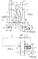
- FIGS. 3 and 3a show a simple exemplary embodiment of an adjusting and latching device 20 which has a bolt 37 which can be inserted into the holes 27 of the columns 11 or 12 and which is provided at the outer end with an eyelet 38 into which a web 36 is seen from above the lower cross member 19 engages.
- FIGS. 4 and 4a Another exemplary embodiment of an adjusting and latching device is shown in FIGS. 4 and 4a.
- a small box-like housing 39 is welded to the end and on the underside of the cross member 19.
- a bolt 40 is held horizontally displaceably in the housing, the outwardly projecting end of which is provided with a handle 41 and towards the inner end wall 45 of the housing 39 with a stop ring 42.
- FIGs 1 and 2 illustrate an advantageous construction of the foot 9 and 10, which consists of a tapering outward triangular in cross section parallel to the plane of Figure 2 box.
- the foot 9 or 10 is given great stability with low weight and material expenditure.
- each foot 9 or 10 is provided with widening supports 62 which can be pushed in under the cable drum 1 and which are held in horizontal guides of the foot.
- the guides, not shown, are expediently attached to the two outer sides of the respective foot parallel to the image plane of FIG. 2. These widening supports serve to increase the stability of the two stands 7 and 8.
- the widening supports can also be designed to be pivotable about vertical fixed pivot bolts. These pivot bolts can be attached to the outer surfaces of the feet in the height region of the lower ends of the columns 11, 12 with corresponding brackets, so that the widening supports can be pivoted about 180 o from a rest position to the side of the feet and into the operating position below the cable drum.
- each stand can easily be brought into place with any vehicle. In the tilting position explained above, each stand can then be brought up with the wheels 25 and 26 to the cable reel in question.
- the crossbeams 15 and 90 and the hydraulic jack 21 are then brought by hand to a cave position on the columns 11, 12 so that the pins 61 can be inserted into the tube 3 or lateral tube socket of the cable drum 1.
- the hydraulic piston 58 with the piston rod 59 and the claw 60 are then brought approximately to the lowest position and the lower traverse with the hydraulic jack 21 is pushed as far as possible on the columns 11 and 12 and the adjusting and locking device 20 in suitable holes in the columns for locking brought.
- the cable reel By actuating the hand levers 56, 57 on both sides, the cable reel can now be raised in that the upper cross members 15 are moved upwards under the pressure of the hydraulic pistons on the columns, while the lower cross members 19 remain in the locking position.
- the widening supports 62 can be brought into the operating position before or after the cable drum is lifted, the widening supports 62 optionally also being able to assume a spread position when they are seated on the pivot pins described. In this operating position of the supports, the strand material can now be wound up or unwound. The disassembly takes place in the opposite way.
Landscapes
- Life Sciences & Earth Sciences (AREA)
- Engineering & Computer Science (AREA)
- Geology (AREA)
- Mechanical Engineering (AREA)
- Structural Engineering (AREA)
- Unwinding Of Filamentary Materials (AREA)
- Storing, Repeated Paying-Out, And Re-Storing Of Elongated Articles (AREA)
Priority Applications (4)
| Application Number | Priority Date | Filing Date | Title |
|---|---|---|---|
| DE58908283T DE58908283D1 (de) | 1989-06-09 | 1989-06-09 | Vorrichtung zum Anheben einer Kabeltrommel. |
| AT89110434T ATE110690T1 (de) | 1989-06-09 | 1989-06-09 | Vorrichtung zum anheben einer kabeltrommel. |
| EP89110434A EP0401412B1 (fr) | 1989-06-09 | 1989-06-09 | Dispositif pour soulever un tambour de câble |
| US07/530,761 US5088654A (en) | 1989-06-09 | 1990-05-30 | Equipment for lifting (and lowering) a cable drum |
Applications Claiming Priority (1)
| Application Number | Priority Date | Filing Date | Title |
|---|---|---|---|
| EP89110434A EP0401412B1 (fr) | 1989-06-09 | 1989-06-09 | Dispositif pour soulever un tambour de câble |
Publications (2)
| Publication Number | Publication Date |
|---|---|
| EP0401412A1 true EP0401412A1 (fr) | 1990-12-12 |
| EP0401412B1 EP0401412B1 (fr) | 1994-08-31 |
Family
ID=8201479
Family Applications (1)
| Application Number | Title | Priority Date | Filing Date |
|---|---|---|---|
| EP89110434A Expired - Lifetime EP0401412B1 (fr) | 1989-06-09 | 1989-06-09 | Dispositif pour soulever un tambour de câble |
Country Status (4)
| Country | Link |
|---|---|
| US (1) | US5088654A (fr) |
| EP (1) | EP0401412B1 (fr) |
| AT (1) | ATE110690T1 (fr) |
| DE (1) | DE58908283D1 (fr) |
Cited By (5)
| Publication number | Priority date | Publication date | Assignee | Title |
|---|---|---|---|---|
| AU2004205347B1 (en) * | 2004-09-01 | 2005-06-02 | Brodally Pty Ltd | A Frame Assembly to Support at Least One Reel |
| FR3002217A1 (fr) * | 2013-02-18 | 2014-08-22 | Telenco Telecomm Engineering Company | Dispositif pour enrouler / derouler un objet allonge |
| CN108249212A (zh) * | 2018-01-30 | 2018-07-06 | 烟台烟大众智知识产权服务有限公司 | 一种用于线缆上的可便携拆装使用的放线架装置 |
| CN113526230A (zh) * | 2021-08-13 | 2021-10-22 | 中铁电气化局集团有限公司 | 用于电力施工的电缆放线器 |
| FR3134572A1 (fr) * | 2022-04-19 | 2023-10-20 | Nexans | Support verrouillable et amovible pour touret |
Families Citing this family (15)
| Publication number | Priority date | Publication date | Assignee | Title |
|---|---|---|---|---|
| US7000900B1 (en) | 2004-01-09 | 2006-02-21 | Robert D. McKinney | Hydraulically powered reel lift |
| US9950906B2 (en) * | 2013-03-13 | 2018-04-24 | Building Materials Investment Corporation | Roll lifting assemblies, systems, and methods |
| US9731921B2 (en) | 2014-07-02 | 2017-08-15 | The Boeing Company | Web roll handling and loading system |
| GB2530543B (en) * | 2014-09-25 | 2017-04-19 | Alfred Cheyne Eng Ltd | Reel drive assembly |
| US9586785B2 (en) * | 2014-12-25 | 2017-03-07 | Innovo Engineering And Construction Ltd | Apparatus for unwinding flexible cables on seabeds and method for loading a reel of flexible cable on said apparatus |
| CN105173877A (zh) * | 2015-10-13 | 2015-12-23 | 国网山东宁津县供电公司 | 多路放线器 |
| CN105293212B (zh) * | 2015-10-27 | 2017-09-05 | 深圳市鹏煜威科技有限公司 | 卷料放料装置 |
| CA2968599A1 (fr) * | 2016-06-01 | 2017-12-01 | Louis J. Sigouin | Pied de verin a support de colonne double |
| FR3059656B1 (fr) * | 2016-12-06 | 2019-06-07 | Nexans | Agencement de deroulement du cable enroule sur un touret |
| US10273111B2 (en) | 2016-12-20 | 2019-04-30 | Sonoco Development, Inc. | Devices for lifting, maneuvering, winding and unwinding reels |
| RU179069U1 (ru) * | 2017-06-19 | 2018-04-25 | Булат Марсович Хамидуллин | Устройство подъема кабельного барабана |
| RU2677407C2 (ru) * | 2017-12-14 | 2019-01-16 | Закрытое акционерное общество Научно-инженерный центр "ИНКОМСИСТЕМ" | Устройство подъема кабельного барабана |
| CN109850673A (zh) * | 2018-11-22 | 2019-06-07 | 上海市安装工程集团有限公司 | 高度可调式电缆放线架及其安装和使用方法 |
| CN110668252A (zh) * | 2019-10-09 | 2020-01-10 | 国网辽宁省电力有限公司盘锦供电公司 | 控制电缆自动放线装置 |
| CN118125358B (zh) * | 2024-05-08 | 2024-07-02 | 山西允能日新科技有限公司 | 一种电力设备运维装置及运维方法 |
Citations (9)
| Publication number | Priority date | Publication date | Assignee | Title |
|---|---|---|---|---|
| DE876556C (de) * | 1951-10-27 | 1953-05-15 | Windenfabrik Gottfried Schober | Winde fuer Kabeltrommeln |
| US2652207A (en) * | 1952-04-21 | 1953-09-15 | Goedken Ray | Linoleum lifter |
| US3275298A (en) * | 1964-06-22 | 1966-09-27 | Steadman Ind Ltd | Demountable containers provided with jack legs for raising and lowering the same |
| DE1961378A1 (de) * | 1968-12-10 | 1970-06-18 | Stephanois Constr Meca | Vorrichtung zum Auf- und/oder Abwickeln von Kabeln |
| FR2067477A5 (en) * | 1969-11-04 | 1971-08-20 | Inst Francais Du Petrole | Flexible pipelines or cable storage drums handling device |
| US3831877A (en) * | 1972-05-30 | 1974-08-27 | J Bennett | Wire pulling apparatus |
| US3944094A (en) * | 1975-01-08 | 1976-03-16 | Compton Ralph M | Warp beam dolly |
| US4148399A (en) * | 1976-12-20 | 1979-04-10 | Carter Jackie L | Bale handling apparatus |
| US4447012A (en) * | 1981-03-12 | 1984-05-08 | Woodruff Harold F | Portable reel jack stand |
Family Cites Families (10)
| Publication number | Priority date | Publication date | Assignee | Title |
|---|---|---|---|---|
| CA539185A (fr) * | 1957-04-09 | H. Bottorff Albert | Support de verin de levage de vehicule | |
| US1732175A (en) * | 1926-08-24 | 1929-10-15 | Thompson James Ross | Jack |
| US1836815A (en) * | 1926-11-05 | 1931-12-15 | Rockbestos Products Corp | Reel stand |
| DE678669C (de) * | 1936-12-06 | 1939-07-20 | Hans Bilstein | Hebevorrichtung, insbesondere fuer Kraftfahrzeuge |
| FR1342266A (fr) * | 1962-09-25 | 1963-11-08 | Nouvelle grue pour atelier | |
| US3165295A (en) * | 1962-12-14 | 1965-01-12 | John L Nolden | Heavy duty jack |
| US3702139A (en) * | 1971-10-05 | 1972-11-07 | Chester C Chaffin | Apparatus for handling carpet rolls |
| US4177978A (en) * | 1978-04-03 | 1979-12-11 | Warsaw Arthur J | Universal shop stand with breakdown feature |
| DE3517696A1 (de) * | 1985-05-17 | 1986-11-20 | Paul Troester Maschinenfabrik, 3000 Hannover | Vorrichtung zum aufwickeln von kaben auf kabeltrommeln |
| US4684310A (en) * | 1985-08-06 | 1987-08-04 | Stange Charles E | Wheel manipulator |
-
1989
- 1989-06-09 AT AT89110434T patent/ATE110690T1/de not_active IP Right Cessation
- 1989-06-09 EP EP89110434A patent/EP0401412B1/fr not_active Expired - Lifetime
- 1989-06-09 DE DE58908283T patent/DE58908283D1/de not_active Expired - Fee Related
-
1990
- 1990-05-30 US US07/530,761 patent/US5088654A/en not_active Expired - Lifetime
Patent Citations (9)
| Publication number | Priority date | Publication date | Assignee | Title |
|---|---|---|---|---|
| DE876556C (de) * | 1951-10-27 | 1953-05-15 | Windenfabrik Gottfried Schober | Winde fuer Kabeltrommeln |
| US2652207A (en) * | 1952-04-21 | 1953-09-15 | Goedken Ray | Linoleum lifter |
| US3275298A (en) * | 1964-06-22 | 1966-09-27 | Steadman Ind Ltd | Demountable containers provided with jack legs for raising and lowering the same |
| DE1961378A1 (de) * | 1968-12-10 | 1970-06-18 | Stephanois Constr Meca | Vorrichtung zum Auf- und/oder Abwickeln von Kabeln |
| FR2067477A5 (en) * | 1969-11-04 | 1971-08-20 | Inst Francais Du Petrole | Flexible pipelines or cable storage drums handling device |
| US3831877A (en) * | 1972-05-30 | 1974-08-27 | J Bennett | Wire pulling apparatus |
| US3944094A (en) * | 1975-01-08 | 1976-03-16 | Compton Ralph M | Warp beam dolly |
| US4148399A (en) * | 1976-12-20 | 1979-04-10 | Carter Jackie L | Bale handling apparatus |
| US4447012A (en) * | 1981-03-12 | 1984-05-08 | Woodruff Harold F | Portable reel jack stand |
Non-Patent Citations (1)
| Title |
|---|
| PATENT ABSTRACTS OF JAPAN, Band 7, Nr. 149 (M-225)[1294], 30. Juni 1983; & JP-A-58 59 159 (TOUSHIBA PLANT KENSETSU K.K.) 08-04-1983 * |
Cited By (6)
| Publication number | Priority date | Publication date | Assignee | Title |
|---|---|---|---|---|
| AU2004205347B1 (en) * | 2004-09-01 | 2005-06-02 | Brodally Pty Ltd | A Frame Assembly to Support at Least One Reel |
| FR3002217A1 (fr) * | 2013-02-18 | 2014-08-22 | Telenco Telecomm Engineering Company | Dispositif pour enrouler / derouler un objet allonge |
| CN108249212A (zh) * | 2018-01-30 | 2018-07-06 | 烟台烟大众智知识产权服务有限公司 | 一种用于线缆上的可便携拆装使用的放线架装置 |
| CN113526230A (zh) * | 2021-08-13 | 2021-10-22 | 中铁电气化局集团有限公司 | 用于电力施工的电缆放线器 |
| FR3134572A1 (fr) * | 2022-04-19 | 2023-10-20 | Nexans | Support verrouillable et amovible pour touret |
| EP4265551A1 (fr) * | 2022-04-19 | 2023-10-25 | Nexans | Support verrouillable et amovible pour touret |
Also Published As
| Publication number | Publication date |
|---|---|
| ATE110690T1 (de) | 1994-09-15 |
| DE58908283D1 (de) | 1994-10-06 |
| EP0401412B1 (fr) | 1994-08-31 |
| US5088654A (en) | 1992-02-18 |
Similar Documents
| Publication | Publication Date | Title |
|---|---|---|
| EP0401412A1 (fr) | Dispositif pour soulever un tambour de câble | |
| DE3046467C2 (fr) | ||
| DE2916429A1 (de) | Vorrichtung zur lagerung, zum transport, zum heben und zum gebrauch von walzdraht | |
| CH642032A5 (de) | Vorrichtung zum auf- und abspulen eines strangfoermigen gutes, auf eine bzw. von einer trommel. | |
| EP0114628A2 (fr) | Dispositif pour débosseler des containers en acier | |
| DE1556337B2 (de) | Verstellbarer Tragrahmen fur Container | |
| DE2250428C3 (de) | Hebegerät für Fahrzeuge, insbesondere Kraftfahrzeuge | |
| EP1506127B1 (fr) | Dispositif de levage pour conteneurs | |
| DE10135594A1 (de) | Hebebühne für Fahrzeuge | |
| EP2316754B1 (fr) | Dispositif souterrain de collecte des déchets | |
| DE3802034C2 (fr) | ||
| DE1431445B2 (de) | Hublader mit s foermiger leitungsfuehrung am zweiteiligen teleskopmast | |
| DE1278708B (de) | Transportabler Turmdrehkran | |
| DE3105621C2 (de) | Vorrichtung zum Auf- und Ausrichten eines auf einem Transportfahrzeug montierten, kippbaren Teleskopmastes | |
| EP3608259B1 (fr) | Agencement de positionnement et d'alignement de conteneurs à coupler les uns aux autres doté de dispositifs pour le positionnement et l'alignement d'un conteneur | |
| DE2825641A1 (de) | Ladeplattform fuer kraftfahrzeuge | |
| AT396585B (de) | Einrichtung zur bedienung von lagerregalen | |
| DE1505332C3 (de) | Einrichtung zum Anheben und Ab senken einer durch Stutzen auf den Erd boden abstellbaren Ladepritsche od dgl | |
| DE3608096C2 (fr) | ||
| DE642021C (de) | Fahrbare Vorrichtung zum Aufbringen von Ersatzraedern auf die Radachse | |
| DE3302960A1 (de) | Kraftfahrzeug mit hebebuehne | |
| DE2108815A1 (de) | Vorrichtung zum Erleichtern des Herausziehens einer Raumschalung | |
| DE2846781A1 (de) | Fahrzeug zum transport von fertiggaragen o.dgl. | |
| DE2326720C3 (de) | Einrichtung zum Umschlag von Abfallstoffen wie Müll | |
| DE2361722C2 (fr) |
Legal Events
| Date | Code | Title | Description |
|---|---|---|---|
| PUAI | Public reference made under article 153(3) epc to a published international application that has entered the european phase |
Free format text: ORIGINAL CODE: 0009012 |
|
| AK | Designated contracting states |
Kind code of ref document: A1 Designated state(s): AT BE CH DE ES FR GB GR IT LI LU NL SE |
|
| 17P | Request for examination filed |
Effective date: 19910605 |
|
| 17Q | First examination report despatched |
Effective date: 19921214 |
|
| GRAA | (expected) grant |
Free format text: ORIGINAL CODE: 0009210 |
|
| AK | Designated contracting states |
Kind code of ref document: B1 Designated state(s): AT BE CH DE ES FR GB GR IT LI LU NL SE |
|
| PG25 | Lapsed in a contracting state [announced via postgrant information from national office to epo] |
Ref country code: IT Free format text: LAPSE BECAUSE OF FAILURE TO SUBMIT A TRANSLATION OF THE DESCRIPTION OR TO PAY THE FEE WITHIN THE PRE;WARNING: LAPSES OF ITALIAN PATENTS WITH EFFECTIVE DATE BEFORE 2007 MAY HAVE OCCURRED AT ANY TIME BEFORE 2007. THE CORRECT EFFECTIVE DATE MAY BE DIFFERENT FROM THE ONE RECORDED.SCRIBED TIME-LIMIT Effective date: 19940831 Ref country code: BE Effective date: 19940831 Ref country code: NL Effective date: 19940831 Ref country code: ES Free format text: THE PATENT HAS BEEN ANNULLED BY A DECISION OF A NATIONAL AUTHORITY Effective date: 19940831 Ref country code: GR Free format text: LAPSE BECAUSE OF FAILURE TO SUBMIT A TRANSLATION OF THE DESCRIPTION OR TO PAY THE FEE WITHIN THE PRESCRIBED TIME-LIMIT Effective date: 19940831 |
|
| REF | Corresponds to: |
Ref document number: 110690 Country of ref document: AT Date of ref document: 19940915 Kind code of ref document: T |
|
| REF | Corresponds to: |
Ref document number: 58908283 Country of ref document: DE Date of ref document: 19941006 |
|
| GBT | Gb: translation of ep patent filed (gb section 77(6)(a)/1977) |
Effective date: 19941214 |
|
| ET | Fr: translation filed | ||
| EAL | Se: european patent in force in sweden |
Ref document number: 89110434.1 |
|
| NLV1 | Nl: lapsed or annulled due to failure to fulfill the requirements of art. 29p and 29m of the patents act | ||
| PG25 | Lapsed in a contracting state [announced via postgrant information from national office to epo] |
Ref country code: LU Free format text: LAPSE BECAUSE OF NON-PAYMENT OF DUE FEES Effective date: 19950630 |
|
| PLBE | No opposition filed within time limit |
Free format text: ORIGINAL CODE: 0009261 |
|
| STAA | Information on the status of an ep patent application or granted ep patent |
Free format text: STATUS: NO OPPOSITION FILED WITHIN TIME LIMIT |
|
| 26N | No opposition filed | ||
| REG | Reference to a national code |
Ref country code: GB Ref legal event code: IF02 |
|
| PGFP | Annual fee paid to national office [announced via postgrant information from national office to epo] |
Ref country code: GB Payment date: 20040527 Year of fee payment: 16 |
|
| PGFP | Annual fee paid to national office [announced via postgrant information from national office to epo] |
Ref country code: AT Payment date: 20040611 Year of fee payment: 16 |
|
| PGFP | Annual fee paid to national office [announced via postgrant information from national office to epo] |
Ref country code: FR Payment date: 20040618 Year of fee payment: 16 |
|
| PGFP | Annual fee paid to national office [announced via postgrant information from national office to epo] |
Ref country code: CH Payment date: 20040623 Year of fee payment: 16 Ref country code: SE Payment date: 20040623 Year of fee payment: 16 |
|
| PGFP | Annual fee paid to national office [announced via postgrant information from national office to epo] |
Ref country code: DE Payment date: 20040728 Year of fee payment: 16 |
|
| PG25 | Lapsed in a contracting state [announced via postgrant information from national office to epo] |
Ref country code: AT Free format text: LAPSE BECAUSE OF NON-PAYMENT OF DUE FEES Effective date: 20050609 Ref country code: GB Free format text: LAPSE BECAUSE OF NON-PAYMENT OF DUE FEES Effective date: 20050609 |
|
| PG25 | Lapsed in a contracting state [announced via postgrant information from national office to epo] |
Ref country code: SE Free format text: LAPSE BECAUSE OF NON-PAYMENT OF DUE FEES Effective date: 20050610 |
|
| PG25 | Lapsed in a contracting state [announced via postgrant information from national office to epo] |
Ref country code: CH Free format text: LAPSE BECAUSE OF NON-PAYMENT OF DUE FEES Effective date: 20050630 Ref country code: LI Free format text: LAPSE BECAUSE OF NON-PAYMENT OF DUE FEES Effective date: 20050630 |
|
| PG25 | Lapsed in a contracting state [announced via postgrant information from national office to epo] |
Ref country code: DE Free format text: LAPSE BECAUSE OF NON-PAYMENT OF DUE FEES Effective date: 20060103 |
|
| REG | Reference to a national code |
Ref country code: CH Ref legal event code: PL |
|
| EUG | Se: european patent has lapsed | ||
| PG25 | Lapsed in a contracting state [announced via postgrant information from national office to epo] |
Ref country code: FR Free format text: LAPSE BECAUSE OF NON-PAYMENT OF DUE FEES Effective date: 20060228 |
|
| GBPC | Gb: european patent ceased through non-payment of renewal fee |
Effective date: 20050609 |
|
| REG | Reference to a national code |
Ref country code: FR Ref legal event code: ST Effective date: 20060228 |