EP0401430B1 - Dispositif pour la séparation des liquides et/ou des matières solides dans des courants gazeux à haute pression - Google Patents
Dispositif pour la séparation des liquides et/ou des matières solides dans des courants gazeux à haute pression Download PDFInfo
- Publication number
- EP0401430B1 EP0401430B1 EP89203119A EP89203119A EP0401430B1 EP 0401430 B1 EP0401430 B1 EP 0401430B1 EP 89203119 A EP89203119 A EP 89203119A EP 89203119 A EP89203119 A EP 89203119A EP 0401430 B1 EP0401430 B1 EP 0401430B1
- Authority
- EP
- European Patent Office
- Prior art keywords
- wall
- vessel
- discharge pipe
- gas
- blades
- Prior art date
- Legal status (The legal status is an assumption and is not a legal conclusion. Google has not performed a legal analysis and makes no representation as to the accuracy of the status listed.)
- Expired - Lifetime
Links
- 239000007788 liquid Substances 0.000 title claims abstract description 21
- 239000007787 solid Substances 0.000 title claims abstract description 13
- 238000000926 separation method Methods 0.000 claims abstract description 8
- 239000007789 gas Substances 0.000 description 52
- VNWKTOKETHGBQD-UHFFFAOYSA-N methane Chemical compound C VNWKTOKETHGBQD-UHFFFAOYSA-N 0.000 description 4
- 230000000694 effects Effects 0.000 description 3
- 230000001133 acceleration Effects 0.000 description 2
- 239000003345 natural gas Substances 0.000 description 2
- 230000002411 adverse Effects 0.000 description 1
- 238000000889 atomisation Methods 0.000 description 1
- 230000002349 favourable effect Effects 0.000 description 1
- 230000005484 gravity Effects 0.000 description 1
- 238000004519 manufacturing process Methods 0.000 description 1
- 239000000463 material Substances 0.000 description 1
- 238000005201 scrubbing Methods 0.000 description 1
- 239000000126 substance Substances 0.000 description 1
Images

Classifications
-
- B—PERFORMING OPERATIONS; TRANSPORTING
- B01—PHYSICAL OR CHEMICAL PROCESSES OR APPARATUS IN GENERAL
- B01D—SEPARATION
- B01D45/00—Separating dispersed particles from gases or vapours by gravity, inertia, or centrifugal forces
- B01D45/12—Separating dispersed particles from gases or vapours by gravity, inertia, or centrifugal forces by centrifugal forces
- B01D45/16—Separating dispersed particles from gases or vapours by gravity, inertia, or centrifugal forces by centrifugal forces generated by the winding course of the gas stream, the centrifugal forces being generated solely or partly by mechanical means, e.g. fixed swirl vanes
-
- B—PERFORMING OPERATIONS; TRANSPORTING
- B04—CENTRIFUGAL APPARATUS OR MACHINES FOR CARRYING-OUT PHYSICAL OR CHEMICAL PROCESSES
- B04C—APPARATUS USING FREE VORTEX FLOW, e.g. CYCLONES
- B04C5/00—Apparatus in which the axial direction of the vortex is reversed
- B04C5/02—Construction of inlets by which the vortex flow is generated, e.g. tangential admission, the fluid flow being forced to follow a downward path by spirally wound bulkheads, or with slightly downwardly-directed tangential admission
-
- B—PERFORMING OPERATIONS; TRANSPORTING
- B04—CENTRIFUGAL APPARATUS OR MACHINES FOR CARRYING-OUT PHYSICAL OR CHEMICAL PROCESSES
- B04C—APPARATUS USING FREE VORTEX FLOW, e.g. CYCLONES
- B04C5/00—Apparatus in which the axial direction of the vortex is reversed
- B04C5/08—Vortex chamber constructions
- B04C5/103—Bodies or members, e.g. bulkheads, guides, in the vortex chamber
Definitions
- the invention relates to a device for separating liquids and/or solids from a high-pressure gas stream, comprising a cylindrical vessel with a virtually vertically set axis fitted with: a top compartment to which the gas stream is fed; a middle compartment comprising a number of blades shaped helicoidally around the axis; a bottom compartment for the separation of the gas and the liquid and/or solids and a coaxial gas discharge pipe projecting upwards from the bottom compartment through the middle and top compartments, around which helicoidal blades have been provided.
- Such a device is known from the United States patent 3,988,132.
- the gas is caused to rotate by the helicoidal blades.
- the separation of liquids and/or solids from the gas stream is the result of the centrifugal effects created in the gas stream, causing the heavier parts to move to the outside of the curved gas stream and accumulate against the inner wall of the vessel, after which they are discharged to a reservoir at the bottom of the vessel as a result of gravity.
- the gas density is a very important quantity with regard to the performance of a centrifugal gas separator.
- the collection efficiency and also the pressure drop of a centrifugal separator attain the most favourable values when the flow through the separator is an ideally ordered centrifugal flow, on which no other flows such as turbulences and secondary flows are superimposed.
- the aim of the invention is to provide a device as mentioned in the preamble which is suitable for separating liquids and/or solids from a high-pressure gas stream, said device having been furnished with means that greatly reduce undesired lateral flows, as a result of which, at unchanged gas flow rate, mass density and vessel dimensions, the collection efficiency is substantially improved and the pressure drop is minimized with respect to similar separators without these means.
- each helicoidal blade is composed of a bottom part with a constant pitch and a part with a pitch which gradually increases in upward direction. This results in a gradual acceleration when the gas is caused to rotate, which leads to a smaller pressure drop of the gas.
- the constant pitch of the blades lies between 5 and 20 degrees and increases gradually in upward direction to a maximum of 60 degrees.
- the constant pitch lies between 10 and 15 degrees and increases in upward direction to a maximum of 45 degrees.
- baffles have been provided between the helicoidal blades, which, viewed in the flow direction of the gas, extend from the outer wall of the gas discharge pipe towards the inner wall of the vessel.
- These baffles are shaped like flat planes, which are by preference not curved but straight. This is done from the point of view for easier manufacturing.
- the length of the straight, flat planes is 0.2 to 0.9 of the distance between the gas discharge pipe and the inner wall of the vessel.
- the baffles and the inner wall of the cylindrical vessel together constitute a gradually narrowing cross section for the gas stream.
- the flat baffles run parallel to the axis of the cylindrical vessel.
- the free ends of the flat baffles are sharp according to the invention.
- the result of this is that the liquid adhering to the baffle and moving towards the free end is not forced round this end to the back of the baffle, as is observed with rounded free ends, but is thrown off the end.
- the liquid was found to be atomized into fine droplets that cannot be collected, which effect increases with the gas pressure.
- At least one conical sleeve section has been installed in the separation section of the cylindrical vessel, on the outside of the gas discharge pipe.
- sleeve sections serve as so-called anti-film skirts, that is, any liquid adhering to the outer wall of the gas discharge pipe is discharged along these conical sleeve sections in the direction of the wall of the cylindrical vessel and does not move towards the outlet of the separator.
- the angle between the sleeve sections and the centre line of the vessel lies between 15 and 45 degrees.
- the distance between the free end of the sleeve sections and the inner wall of the vessel is between 0.25 and 0.70 and by preference between 0.3 and 0.6 of the distance between the outer wall of the gas discharge pipe and the inner wall of the cylindrical vessel.
- the collection efficiency obtained for liquids and/or solids with the means according to the invention amounts to 99.5-100% and a decrease in pressure drop is obtained of approx. 22% with respect to a gas scrubber without these means.
- the gas to be scrubbed is fed into the top compartment 1 of the separator via the pipe nozzle 3.
- the blades 5 present in the middle compartment 4 cause the gas to rotate in order to convert the flow energy of the gas into a centrifugal force, required for the separation.
- the liquid and/or solid matter separated off accumulates on the inner wall of the vessel 2 and then moves downwards and is caused to settle by the plates 7, 8 and 9.
- the material separated off is discharged via pipe 10 and valve 11.
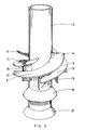
- the scrubbed gas is discharged via gas discharge pipe 12, which is mounted coaxially with the vessel 2 and projects upwards from the bottom compartment 6 through the middle compartment 4 and the top compartment 1.
- the helicoidal blades 5 are fixed to the gas discharge pipe 12 at some distance from one another and partially overlap one another, thus creating the desired curved channel.
- Each helicoidal blade 5 is composed of a bottom section 13 with a constant pitch and a section 14 with a pitch that gradually increases in upward direction. This causes a gradual acceleration of the gas fed into the separator 2, which results in a smaller pressure drop when the gas is caused to rotate.
- the constant pitch of the blades 5 lies between 5 and 20 ⁇ , preferably between 10 and 15 ⁇ , and increases to at most 60 ⁇ , preferably at most 45 ⁇ , near the gas inlet section.
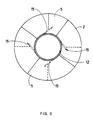
- Between the blades 5 are vertical baffles 15, which, viewed in the flow direction of the gas, extend from the gas discharge tube 12 in the direction of the inner wall of the vessel 2. These baffles 15 are shaped like flat planes. These baffles improve the liquid separating capacity. This is improved even more when the free ends of the baffles are sharp, as is shown in fig. 3.
- the device according to the invention can be used to purify gases under high pressure, that is, pressures of more than 8 bar up to even 100 bar or more. This has been demonstrated in recent tests with natural gas at pressures of 150 bar.
Landscapes
- Chemical & Material Sciences (AREA)
- Chemical Kinetics & Catalysis (AREA)
- Physics & Mathematics (AREA)
- Fluid Mechanics (AREA)
- Separating Particles In Gases By Inertia (AREA)
- Physical Or Chemical Processes And Apparatus (AREA)
- Centrifugal Separators (AREA)
- Organic Low-Molecular-Weight Compounds And Preparation Thereof (AREA)
- Gas Separation By Absorption (AREA)
Claims (11)
- Dispositif pour séparer des liquides et/ou des solides d'un courant de gaz à haute pression, comprenant un récipient cylindrique (2) ayant un axe d'écoulement pratiquement vertical équipé:- d'un compartiment supérieur (1) dans lequel le courant gazeux est introduit;- d'un compartiment médian (4) comportant un certain nombre d'ailettes (5) formées hélicoïdalement autour de l'axe;- d'un compartiment inférieur (6) pour la séparation du gaz et du liquide et/ou des solides et d'un tuyau d'évacuation de gaz coaxial (12) s'élevant vers le haut à partir du compartiment inférieur à travers les compartiments médian et supérieur, caractérisé en ce que chaque ailette hélicoïdale est fixée autour dudit tuyau d'évacuation de gaz, et se compose d'une partie inférieure de pas constant et d'une partie de pas croissant graduellement en direction du haut.
- Dispositif conforme à la revendication 1, caractérisé en ce que le pas constant des ailettes est compris entre 5 et 20 degrés et croît graduellement en direction du haut jusqu'à 60 degrés au maximum.
- Dispositif conforme aux revendications 1 et 2, caractérisé en ce que le pas constant des ailettes est compris entre 10 et 15 degrés et croît en direction du haut jusqu'à 45 degrés au maximum.
- Dispositif conforme à l'une quelconque des revendications 1 à 3, caractérisé en ce que des chicanes verticales (15) sont prévues entre les ailettes hélicoïdales (5), ces chicanes étant disposées parallèlement à l'axe vertical du récipient cylindrique (2) et s'étendant à partir du tuyau d'évacuation (12) en direction de la paroi interne du récipient.
- Dispositif conforme à la revendication 4, caractérisé en ce que les chicanes (15) sont fabriquées sous forme de plans plats et droits.
- Dispositif conforme à l'une des revendications 4 et 5, caractérisé en ce que les chicanes plates s'étendent sur une distance qui est de 0,2 à 0,9 fois la distance entre le tuyau d'évacuation de gaz (12) et la paroi interne du récipient (2).
- Dispositif conforme à l'une quelconque des revendications 4 à 6, caractérisé en ce que les extrémités libres des chicanes (15) sont tranchantes.
- Dispositif conforme à l'une quelconque des revendications 1 à 7, caractérisé en ce que au moins un tronçon de manchon conique (16, 17), ayant sa grande base tournée vers le bas, est prévu à la paroi externe du tuyau d'évacuation de gaz, dans le compartiment inférieur (6) du dispositif.
- Dispositif conforme à la revendication 8, caractérisé en ce que l'angle entre les tronçons de manchons et l'axe vertical du récipient est compris entre 15 et 45 degrés.
- Dispositif conforme à l'une quelconque des revendications 8 et 9, caractérisé en ce que la distance entre l'extrémité libre des tronçons de manchons (16, 17) et la paroi interne du récipient est comprise entre 0,25 et 0,70 fois la distance entre la paroi externe du tuyau d'évacuation de gaz (12) et la paroi interne du récipient cylindrique (2).
- Dispositif conforme à l'une quelconque des revendications 8 à 10, caractérisé en ce que la distance entre l'extrémité libre des tronçons de manchons (16, 17) et la paroi interne du récipient est comprise entre 0,3 et 0,6 fois la distance entre la paroi externe du tuyau d'évacuation de gaz (12) et la paroi interne du récipient (2).
Priority Applications (1)
| Application Number | Priority Date | Filing Date | Title |
|---|---|---|---|
| AT89203119T ATE86512T1 (de) | 1989-06-06 | 1989-12-08 | Einrichtung zur trennung von fluessigkeiten und/oder feststoffen aus einem hochdruckgasstrom. |
Applications Claiming Priority (2)
| Application Number | Priority Date | Filing Date | Title |
|---|---|---|---|
| NL8901429 | 1989-06-06 | ||
| NL8901429A NL8901429A (nl) | 1989-06-06 | 1989-06-06 | Inrichting voor het afscheiden van vloeistoffen en/of vaste stoffen uit een hogedruk gasstroom. |
Publications (2)
| Publication Number | Publication Date |
|---|---|
| EP0401430A1 EP0401430A1 (fr) | 1990-12-12 |
| EP0401430B1 true EP0401430B1 (fr) | 1993-03-10 |
Family
ID=19854781
Family Applications (1)
| Application Number | Title | Priority Date | Filing Date |
|---|---|---|---|
| EP89203119A Expired - Lifetime EP0401430B1 (fr) | 1989-06-06 | 1989-12-08 | Dispositif pour la séparation des liquides et/ou des matières solides dans des courants gazeux à haute pression |
Country Status (7)
| Country | Link |
|---|---|
| US (1) | US5224976A (fr) |
| EP (1) | EP0401430B1 (fr) |
| AT (1) | ATE86512T1 (fr) |
| CA (1) | CA2018251C (fr) |
| DE (1) | DE68905334D1 (fr) |
| NL (1) | NL8901429A (fr) |
| NO (1) | NO176309C (fr) |
Families Citing this family (14)
| Publication number | Priority date | Publication date | Assignee | Title |
|---|---|---|---|---|
| GB2299076A (en) * | 1995-03-09 | 1996-09-25 | Mass Transfer International Lt | Packing elements |
| EP1208897A1 (fr) | 2000-11-21 | 2002-05-29 | Epcon Norge AS | Réservoir pour flottation et dégazage combiné |
| NO320957B1 (no) * | 2002-10-02 | 2006-02-20 | Statoil Asa | Separasjonsenhet |
| NL1026268C2 (nl) * | 2004-05-26 | 2005-11-30 | Flash Technologies N V | In-lijn cycloonscheider. |
| KR20070101056A (ko) * | 2006-04-10 | 2007-10-16 | 삼성전자주식회사 | 사이클론 및 사이클론 공기청정기 |
| JP2011016095A (ja) * | 2009-07-09 | 2011-01-27 | Sumco Techxiv株式会社 | サイクロン装置 |
| EA201390989A1 (ru) * | 2010-12-30 | 2014-06-30 | Айванхо Энерджи Инк. | Способ, система и устройство для разделения в обработке исходных сырьевых материалов |
| US8973215B2 (en) * | 2012-07-18 | 2015-03-10 | Techtronic Floor Care Technology Limited | Cyclonic vacuum cleaner and dirt separator |
| US8997310B2 (en) | 2012-10-12 | 2015-04-07 | Electrolux Home Care Products, Inc. | Vacuum cleaner cyclone with helical cyclone expansion region |
| USD689658S1 (en) * | 2012-12-12 | 2013-09-10 | Electrolux Home Care Products, Inc. | Exterior surface of a cyclone receptacle |
| CA2844330C (fr) | 2013-02-25 | 2019-10-15 | Bruce Lyon | Separateur de sable |
| RU2545277C1 (ru) * | 2014-01-17 | 2015-03-27 | Роман Борисович Филиппов | Способ разделения неоднородных смесей в центробежном поле |
| EP4180111B1 (fr) * | 2018-05-18 | 2024-11-13 | Donaldson Company, Inc. | Agencement de pré-nettoyeur destiné à être utilisé dans la filtration d'air |
| US11154873B2 (en) * | 2019-09-19 | 2021-10-26 | X'pole Precision Tools Inc. | Multi-cyclonic dust filter device |
Family Cites Families (14)
| Publication number | Priority date | Publication date | Assignee | Title |
|---|---|---|---|---|
| US1573135A (en) * | 1926-02-16 | Dust collector | ||
| US1565318A (en) * | 1925-04-06 | 1925-12-15 | Ernest F Fisher | Separator |
| US2045503A (en) * | 1935-01-17 | 1936-06-23 | Bartlett Hayward Co | Dust collector |
| US2692655A (en) * | 1951-12-28 | 1954-10-26 | Vilbiss Co | Air cleaner |
| US3169842A (en) * | 1962-04-16 | 1965-02-16 | Coopers Mech Joints | Cyclones for removing solids from gas |
| DE1236121B (de) * | 1962-08-09 | 1967-03-09 | Lorch Ges & Co K G J | Abscheider fuer fluessige und feste Fremdstoffe aus Druckluft |
| FR1504489A (fr) * | 1966-05-18 | 1967-12-08 | Réservoir de condensation | |
| US3386588A (en) * | 1966-10-14 | 1968-06-04 | Sundstrand Corp | Coolant filter |
| US3590558A (en) * | 1968-11-15 | 1971-07-06 | Combustion Eng | Particle-from-fluid separator |
| US3771295A (en) * | 1969-07-31 | 1973-11-13 | H Wheeler | Separater apparatus for handling compressed air |
| US3822533A (en) * | 1972-03-04 | 1974-07-09 | Nederlandse Gasunie Nv | Device for removing impurities from gases |
| NL177187C (nl) * | 1974-01-16 | 1985-08-16 | Nederlandse Gasunie Nv | Inrichting voor het afscheiden van verontreinigingen uit gassen. |
| DE2909318A1 (de) * | 1979-03-09 | 1980-09-11 | Ktd Verfahrenstech | Abscheider fuer feste und fluessige stoffe aus einem gasstrom |
| SE440978B (sv) * | 1983-08-25 | 1985-09-02 | Tetra Pak Int | Anordning for separering av partiklar fran gas, speciellt vid tillverkning av aseptiska forpackningsbehallare |
-
1989
- 1989-06-06 NL NL8901429A patent/NL8901429A/nl not_active Application Discontinuation
- 1989-12-08 EP EP89203119A patent/EP0401430B1/fr not_active Expired - Lifetime
- 1989-12-08 AT AT89203119T patent/ATE86512T1/de not_active IP Right Cessation
- 1989-12-08 DE DE8989203119T patent/DE68905334D1/de not_active Expired - Lifetime
- 1989-12-11 US US07/488,296 patent/US5224976A/en not_active Expired - Lifetime
-
1990
- 1990-06-05 CA CA002018251A patent/CA2018251C/fr not_active Expired - Lifetime
- 1990-06-05 NO NO902481A patent/NO176309C/no not_active IP Right Cessation
Also Published As
| Publication number | Publication date |
|---|---|
| NO176309B (no) | 1994-12-05 |
| DE68905334D1 (de) | 1993-04-15 |
| US5224976A (en) | 1993-07-06 |
| EP0401430A1 (fr) | 1990-12-12 |
| CA2018251A1 (fr) | 1990-12-06 |
| CA2018251C (fr) | 2000-05-02 |
| NO902481L (no) | 1990-12-07 |
| NL8901429A (nl) | 1991-01-02 |
| ATE86512T1 (de) | 1993-03-15 |
| NO902481D0 (no) | 1990-06-05 |
| NO176309C (no) | 1995-03-15 |
Similar Documents
| Publication | Publication Date | Title |
|---|---|---|
| CA2018251C (fr) | Dispositif de separation de liquides et/ou de solides dans un jet gazeux haute pression | |
| CA2031327C (fr) | Appareil effectuant la separation de matieres liquides et solides contenues dans un flux gazeux | |
| US7025890B2 (en) | Dual stage centrifugal liquid-solids separator | |
| CN102725070B (zh) | 具有后接离心式分离器的重力式预分离器的分离设备 | |
| US6270544B1 (en) | Cyclone separator having a tubular member with slit-like openings surrounding a central outlet pipe | |
| CN101949380B (zh) | 一种压缩机分离器除沫装置 | |
| US4731228A (en) | Reactor and horizontal cyclone separator with primary mass flow and secondary centrifugal separation of solid and fluid phases | |
| US20020162806A1 (en) | Inclined free water knockout (IFWKO) | |
| US6805734B1 (en) | Compact cascade scrubber for scrubbing exhaust gas | |
| US5743926A (en) | Apparatus for separation of liquid and vapor in distillation/flashing process | |
| CN120393602A (zh) | 一种气液分离装置及气液分离方法 | |
| SU1301459A1 (ru) | Сепаратор дл очистки газов и паров | |
| US5279727A (en) | Open-bottomed cyclone with solids separation tube and method | |
| AU642730B2 (en) | Cyclone separator | |
| DE2224458A1 (de) | Zyklon-abscheider | |
| WO2002020137A2 (fr) | Separateur d'eau | |
| CN212119425U (zh) | 一种高效聚结除雾装置 | |
| RU2299757C2 (ru) | Фильтр-сепаратор | |
| CN2212455Y (zh) | 一种新型高效气液分离装置 | |
| CA1136071A (fr) | Separateur horizontal de vapeur et de liquide en melange | |
| SU1648536A1 (ru) | Центробежный сепаратор | |
| SU904792A1 (ru) | Вихревой сепаратор | |
| RU19270U1 (ru) | Циклон | |
| SU1066629A1 (ru) | Сепаратор | |
| RU2196642C1 (ru) | Гидроциклонная сепарационная установка |
Legal Events
| Date | Code | Title | Description |
|---|---|---|---|
| PUAI | Public reference made under article 153(3) epc to a published international application that has entered the european phase |
Free format text: ORIGINAL CODE: 0009012 |
|
| AK | Designated contracting states |
Kind code of ref document: A1 Designated state(s): AT BE CH DE ES FR GB GR IT LI LU NL SE |
|
| 17P | Request for examination filed |
Effective date: 19910516 |
|
| 17Q | First examination report despatched |
Effective date: 19920515 |
|
| GRAA | (expected) grant |
Free format text: ORIGINAL CODE: 0009210 |
|
| AK | Designated contracting states |
Kind code of ref document: B1 Designated state(s): AT BE CH DE ES FR GB GR IT LI LU NL SE |
|
| PG25 | Lapsed in a contracting state [announced via postgrant information from national office to epo] |
Ref country code: GR Free format text: LAPSE BECAUSE OF FAILURE TO SUBMIT A TRANSLATION OF THE DESCRIPTION OR TO PAY THE FEE WITHIN THE PRESCRIBED TIME-LIMIT Effective date: 19930310 Ref country code: DE Effective date: 19930310 Ref country code: ES Free format text: THE PATENT HAS BEEN ANNULLED BY A DECISION OF A NATIONAL AUTHORITY Effective date: 19930310 Ref country code: AT Effective date: 19930310 |
|
| REF | Corresponds to: |
Ref document number: 86512 Country of ref document: AT Date of ref document: 19930315 Kind code of ref document: T |
|
| REF | Corresponds to: |
Ref document number: 68905334 Country of ref document: DE Date of ref document: 19930415 |
|
| ITF | It: translation for a ep patent filed | ||
| ET | Fr: translation filed | ||
| PG25 | Lapsed in a contracting state [announced via postgrant information from national office to epo] |
Ref country code: CH Effective date: 19931231 Ref country code: LU Free format text: LAPSE BECAUSE OF NON-PAYMENT OF DUE FEES Effective date: 19931231 Ref country code: LI Effective date: 19931231 |
|
| PLBE | No opposition filed within time limit |
Free format text: ORIGINAL CODE: 0009261 |
|
| STAA | Information on the status of an ep patent application or granted ep patent |
Free format text: STATUS: NO OPPOSITION FILED WITHIN TIME LIMIT |
|
| 26N | No opposition filed | ||
| REG | Reference to a national code |
Ref country code: CH Ref legal event code: PL |
|
| ITTA | It: last paid annual fee | ||
| EAL | Se: european patent in force in sweden |
Ref document number: 89203119.6 |
|
| REG | Reference to a national code |
Ref country code: GB Ref legal event code: IF02 |
|
| PGFP | Annual fee paid to national office [announced via postgrant information from national office to epo] |
Ref country code: NL Payment date: 20081219 Year of fee payment: 20 |
|
| PGFP | Annual fee paid to national office [announced via postgrant information from national office to epo] |
Ref country code: IT Payment date: 20081211 Year of fee payment: 20 Ref country code: SE Payment date: 20081211 Year of fee payment: 20 |
|
| PGFP | Annual fee paid to national office [announced via postgrant information from national office to epo] |
Ref country code: GB Payment date: 20081218 Year of fee payment: 20 |
|
| PGFP | Annual fee paid to national office [announced via postgrant information from national office to epo] |
Ref country code: BE Payment date: 20090119 Year of fee payment: 20 |
|
| PGFP | Annual fee paid to national office [announced via postgrant information from national office to epo] |
Ref country code: FR Payment date: 20081215 Year of fee payment: 20 |
|
| REG | Reference to a national code |
Ref country code: GB Ref legal event code: PE20 Expiry date: 20091207 |
|
| BE20 | Be: patent expired |
Owner name: NEDERLANDSE *GASUNIE N.V. Effective date: 20091208 |
|
| NLV7 | Nl: ceased due to reaching the maximum lifetime of a patent |
Effective date: 20091208 |
|
| PG25 | Lapsed in a contracting state [announced via postgrant information from national office to epo] |
Ref country code: NL Free format text: LAPSE BECAUSE OF EXPIRATION OF PROTECTION Effective date: 20091208 |
|
| PG25 | Lapsed in a contracting state [announced via postgrant information from national office to epo] |
Ref country code: GB Free format text: LAPSE BECAUSE OF EXPIRATION OF PROTECTION Effective date: 20091207 |