EP0401514A2 - Nachgiebige Schaltbereichsverriegelung - Google Patents
Nachgiebige Schaltbereichsverriegelung Download PDFInfo
- Publication number
- EP0401514A2 EP0401514A2 EP90108485A EP90108485A EP0401514A2 EP 0401514 A2 EP0401514 A2 EP 0401514A2 EP 90108485 A EP90108485 A EP 90108485A EP 90108485 A EP90108485 A EP 90108485A EP 0401514 A2 EP0401514 A2 EP 0401514A2
- Authority
- EP
- European Patent Office
- Prior art keywords
- transmission
- range
- shift
- section
- interlock
- Prior art date
- Legal status (The legal status is an assumption and is not a legal conclusion. Google has not performed a legal analysis and makes no representation as to the accuracy of the status listed.)
- Granted
Links
- 230000005540 biological transmission Effects 0.000 claims abstract description 108
- 150000001875 compounds Chemical class 0.000 claims abstract description 25
- 230000007935 neutral effect Effects 0.000 claims abstract description 18
- 230000001052 transient effect Effects 0.000 claims abstract description 5
- 230000002401 inhibitory effect Effects 0.000 claims abstract 2
- 230000001360 synchronised effect Effects 0.000 claims description 17
- 230000002441 reversible effect Effects 0.000 claims description 16
- 230000008859 change Effects 0.000 claims description 6
- 238000006073 displacement reaction Methods 0.000 claims description 5
- 230000000712 assembly Effects 0.000 description 7
- 238000000429 assembly Methods 0.000 description 7
- 230000007246 mechanism Effects 0.000 description 6
- 230000009467 reduction Effects 0.000 description 4
- 241000219098 Parthenocissus Species 0.000 description 1
- 230000008676 import Effects 0.000 description 1
- 230000000977 initiatory effect Effects 0.000 description 1
- 230000003993 interaction Effects 0.000 description 1
- 230000009347 mechanical transmission Effects 0.000 description 1
- 230000004048 modification Effects 0.000 description 1
- 238000012986 modification Methods 0.000 description 1
- 230000008707 rearrangement Effects 0.000 description 1
- 230000004044 response Effects 0.000 description 1
- 238000012795 verification Methods 0.000 description 1
Images


Classifications
-
- F—MECHANICAL ENGINEERING; LIGHTING; HEATING; WEAPONS; BLASTING
- F16—ENGINEERING ELEMENTS AND UNITS; GENERAL MEASURES FOR PRODUCING AND MAINTAINING EFFECTIVE FUNCTIONING OF MACHINES OR INSTALLATIONS; THERMAL INSULATION IN GENERAL
- F16H—GEARING
- F16H63/00—Control outputs from the control unit to change-speed- or reversing-gearings for conveying rotary motion or to other devices than the final output mechanism
- F16H63/02—Final output mechanisms therefor; Actuating means for the final output mechanisms
- F16H63/30—Constructional features of the final output mechanisms
- F16H63/34—Locking or disabling mechanisms
- F16H63/36—Interlocking devices
-
- F—MECHANICAL ENGINEERING; LIGHTING; HEATING; WEAPONS; BLASTING
- F16—ENGINEERING ELEMENTS AND UNITS; GENERAL MEASURES FOR PRODUCING AND MAINTAINING EFFECTIVE FUNCTIONING OF MACHINES OR INSTALLATIONS; THERMAL INSULATION IN GENERAL
- F16H—GEARING
- F16H63/00—Control outputs from the control unit to change-speed- or reversing-gearings for conveying rotary motion or to other devices than the final output mechanism
- F16H63/40—Control outputs from the control unit to change-speed- or reversing-gearings for conveying rotary motion or to other devices than the final output mechanism comprising signals other than signals for actuating the final output mechanisms
- F16H63/44—Signals to the control unit of auxiliary gearing
-
- Y—GENERAL TAGGING OF NEW TECHNOLOGICAL DEVELOPMENTS; GENERAL TAGGING OF CROSS-SECTIONAL TECHNOLOGIES SPANNING OVER SEVERAL SECTIONS OF THE IPC; TECHNICAL SUBJECTS COVERED BY FORMER USPC CROSS-REFERENCE ART COLLECTIONS [XRACs] AND DIGESTS
- Y10—TECHNICAL SUBJECTS COVERED BY FORMER USPC
- Y10T—TECHNICAL SUBJECTS COVERED BY FORMER US CLASSIFICATION
- Y10T74/00—Machine element or mechanism
- Y10T74/19—Gearing
- Y10T74/19167—In series plural interchangeably locked nonplanetary units
-
- Y—GENERAL TAGGING OF NEW TECHNOLOGICAL DEVELOPMENTS; GENERAL TAGGING OF CROSS-SECTIONAL TECHNOLOGIES SPANNING OVER SEVERAL SECTIONS OF THE IPC; TECHNICAL SUBJECTS COVERED BY FORMER USPC CROSS-REFERENCE ART COLLECTIONS [XRACs] AND DIGESTS
- Y10—TECHNICAL SUBJECTS COVERED BY FORMER USPC
- Y10T—TECHNICAL SUBJECTS COVERED BY FORMER US CLASSIFICATION
- Y10T74/00—Machine element or mechanism
- Y10T74/20—Control lever and linkage systems
- Y10T74/20012—Multiple controlled elements
- Y10T74/20018—Transmission control
- Y10T74/20085—Restriction of shift, gear selection, or gear engagement
- Y10T74/20104—Shift element interlock
- Y10T74/20116—Resiliently biased interlock
Definitions
- the present invention relates to a range interlock for a compound range type mechanical transmission which will inhibit shifting of the main transmission section from neutral during a range shift transient, and in particular, to a resilient range interlock for a compound transmission which will resiliently inhibit, but not prohibit, shifting of a compound transmission from neutral during a range shift transient.
- Compound transmission systems comprising manually shifted multi-speed main transmission sections connected in series with one or more multi-speed auxiliary drivetrain sections, usually of the range, splitter or combined range/splitter type are well known in the prior art.
- the auxiliary sections are usually input and/or output auxiliary transmission sections but may also be multi-speed drive axles, transfer cases or the like. Examples of such compound systems may be seen by reference to U.S. Patent Nos. 4,754,665; 3,648,546; 3,429,202; 4,455,883; 4,561,325; 4,663,725, 3,799,002; 4,455,883 and 4,527,446, the disclosures of which are hereby incorporated by reference. These transmissions, are well received and widely utilized in manually shifted heavy duty vehicles.
- a compound transmission comprising a multiple speed main transmission section connected in series with a multiple speed auxiliary section including at least two-speed range gearing.
- the shift control for the transmission includes a shift bar housing actuated by a standard shift lever or cross-shaft shift finger and defines two distinct positions for moving the shift bar and shift fork associated with the main section ratio or ratios compounded by the two-speed auxiliary range ratio.
- a resilient interlock is actuated during auxiliary section range ratio shift transients to inhibit, but not prohibit, shifting of the mainsection from neutral until the range shift in the auxiliary section is completed.
- the range section may be shifted by a control lever or button, usually mounted at or on the shift lever.
- the resilient interlock may be overcome allowing the main section to be shifted from neutral into a selected ratio.
- compound transmission is used to designate a change speed or change gear transmission having a main transmission section and an auxiliary drive train unit, such as an auxiliary transmission section, connected in series whereby the selected gear reduction in the main transmission section may be compounded by further selected gear reduction in the auxiliary transmission section.
- upshift shall mean the shifting from a lower speed gear ratio to a higher speed gear ratio
- downshift shall mean the shifting from a higher speed gear ratio to a lower speed gear ratio.
- low speed gear or “low gear” as used herein shall designate a gear utilized for relatively lower forward speed operation in a transmission, i.e., a set of gears having a higher ratio of reduction of output shaft speed relative to the speed of the input shaft.
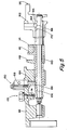
- Transmission 10 comprises a main transmission section 12 connected in series with an auxiliary transmission section 14 having both range and splitter type gearing.
- transmission 10 is housed within a single multi-piece housing 16 and includes an input shaft 18 driven by a prime mover such as a diesel engine (not shown) through a selectively disengaged, normally engaged, friction master clutch (not shown).
- a prime mover such as a diesel engine (not shown) through a selectively disengaged, normally engaged, friction master clutch (not shown).
- the input shaft 18 carries an input gear 20 for driving at least one countershaft assembly 22.
- input gear 20 simultaneously drives a plurality of substantially identical mainsection countershaft assemblies at substantially identical rotational speeds.
- Each of the mainsection countershaft assemblies comprises a mainsection countershaft 24 supported by bearings 26 and 28 in housing 16 and is provided with mainsection countershaft gears 30, 32, 34, 36 and 38 fixed thereto.
- a plurality of mainsection drive or mainshaft gears 40, 42 and 44 surround the transmission mainshaft 46 and are selectively clutchable, one at a time, to the mainshaft 46 for rotation therewith by sliding clutch collars 48 and 50 as is well known in the art.
- Clutch collar 48 may also be utilized to clutch input gear 20 to the mainshaft 46 to provide a direct drive relationship between the input shaft 18 and the mainshaft 46.
- each of the mainsection mainshaft gears encircles the mainshaft 46 and is in continuous meshing engagement with and is floatingly supported by the associated countershaft gear groups, which mounting means and special advantages resulting therefrom are explained in greater detail in above-mentioned United States Patent Nos. 3,105,395 and 3,335,616.
- clutch collars 48 and 50 are axially positioned by means of shift forks or yokes 52 and 54, respectively, associated with a shift bar housing assembly 56 to be described in greater detail below.
- Clutch collars 48 and 50 are, in the preferred embodiment, of the well known non-synchronized double acting jaw clutch type.
- Main section mainshaft gear 44 is the reverse gear and is in continuous meshing engagement with countershaft gears 38 by means of conventional intermediate idler gears 57 (see Fig 1A).
- Main section countershaft gear 32 is provided for powering power takeoff devices and the like.
- Jaw clutches 48 and 50 are three-position clutches in that they may be positioned in a centered axially nondisplaced, nonengaged position as illustrated or in a fully rightwardly engaged or fully leftwardly engaged position.
- Auxiliary transmission section 14 is connected in series with main transmission section 12 and is of the three-layer, four speed combined splitter/range type as illustrated in above-mentioned United States Patent No. 4,754,665.
- Mainshaft 46 extends into the auxiliary section 14 and is journaled in the inward end of the output shaft 58 which extends from the rearward end of the transmission.
- Auxiliary transmission section 14 includes, in the preferred embodiment thereof, a plurality of substantially identical auxiliary countershaft assemblies 60 (see Figure 1A) each comprising an auxiliary countershaft 62 supported by bearings 64 and 66 in housing 16 and carrying three auxiliary section countershaft gears 68, 70 and 72 fixed for rotation therewith.
- Auxiliary countershaft gears 68 are constantly meshed with and support auxiliary section splitter gear 74.
- Auxiliary countershaft gears 70 are constantly meshed with and support auxiliary section splitter/range gear 76 which surrounds the output shaft 58 at the end thereof adjacent the coaxial inner end of mainshaft 46.
- Auxiliary section countershaft gears 72 constantly mesh with and support auxiliary section range gear 78 which surrounds the output shaft 58.
- auxiliary section countershaft gears 68 and splitter gear 74 define a first gear layer
- auxiliary section countershaft gears 70 and splitter/range gear 76 define a second gear layer
- auxiliary section countershaft gears 72 and range gear 78 define a third layer, or gear group, of the combined splitter and range type auxiliary transmission section 14.
- a sliding two-position jaw clutch collar 80 is utilized to selectively couple either the splitter gear 74 or the splitter/range gear 76 to the mainshaft 46 while a two-position synchronized clutch assembly 82 utilized to selectively couple the splitter/range gear 76 or the range gear 78 to the output shaft 58.
- the structure and function of double-acting jaw clutch collar 80 is substantially identical to the structure and function of the sliding clutch collars 48 and 50 utilized in the main transmission section 12 and the function of double-acting synchronized clutch assembly 82 is substantially identical to the structure and function of prior art double-acting synchronized clutch assembly, examples of which may be seen by reference to United States Patent Nos.
- the splitter jaw clutch 80 is a two-position clutch assembly which may be selectively positioned in the rightwardmost or leftwardmost positions for engaging either gear 76 or gear 74, respectively, to the mainshaft 46.
- Splitter jaw clutch 80 is axially positioned by means of a shift fork 84 controlled by a two-position piston actuator 86 which is operable by a driver selection switch such as a button or the like on the shift knob (not shown) as is known in the prior art.
- Two-position synchronized clutch assembly 82 is also a two-position clutch which may be selectively positioned in either the rightwardmost or leftwardmost positions thereof for selectively clutching either gear 78 or 76, respectively, to output shaft 58.
- Clutch assembly 82 is positioned by means of a shift fork 88 operated by means of a two-position piston device 90, the actuation and control of which will be described in greater detail below.
- auxiliary transmission section 14 is a three layer auxiliary section of the combined range and splitter type providing four selectable speeds or drive ratios between the input (mainshaft 46) and output (output shaft 58) thereof.
- the mainsection 12 provides a reverse and three potentially selectable forward speeds.
- one of the selectable mainsection forward gear ratios, the low speed gear ratios associated with mainshaft gear 42, is not utilized in the high range.
- transmission 10 is properly designated as a "(2+1) X (2X2)" type transmission providing nine or ten selectable forward speeds, depending upon the desirability and practicality of splitting the low gear ratio.
- clutch 82 the range clutch
- clutch collar 80 the splitter clutch
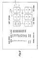
- the shift pattern for shifting transmission 10 is schematically illustrated in Figure 2. Divisions in the vertical direction at each gear lever position signify splitter shifts while movement in the horizontal direction from the three/four and five/six leg of the H pattern to the seven/eight and nine/ten leg of the H pattern signifies a shift from the low range to the high range of the transmission.
- splitter shifting is accomplished in the usual manner by means of a vehicle operator actuated splitter button or the like, usually a button located at the shift lever knob while operation of the range clutch shifting assembly is an automatic response to movement of the gear shift lever between the central and rightwardmost legs of the shift pattern as illustrated in Figure 2 and will be described in greater detail below.
- Range shift devices of this general type are known in the prior art and may be seen by reference to above-mentioned United States Patent Nos. 3,429,202; 4,455,883; 4,561,325 and 4,663,725.
- N the number of mainsection ratio steps occurring in both ranges
- gearing to approximate these ratios is selected.
- the splitter steps are about 33.3% while the range step is about 316% which is generally suitable for a "2+1" main transmission section having about 78% steps as the square root of 1.78 equals about 1.33 and 1.78 raised to the second power (i.e. N equals 2) equals about 3.16.
- Shift control unit or assembly for controlling shifting of the main transmission section 12 and the range portion, clutch 82, of the auxiliary section 14 of transmission 10 is defined by the shift bar housing assembly 56.
- shift bar housing assembly 56 includes a housing 94 which is mountable to the upper opening provided in transmission housing 16 and which may carry the range clutch actuating piston assembly 96 thereto.
- Shift bar housing 94 supports a first shift bar (also called “shift bar” and/or "shift rail") 96 and a second shift bar 98 for independent axial movement therein.
- Shift bar 96 carries shift fork 54 for axial movement therewith and shift bar 98 carries shift fork 52 for axial movement therewith.
- Shift bar housing 94 also supports a control shaft 100 for axial and rotational movement therein. Shift rails 96 and 98 and control shaft 100 are axially movable about axes 102, 104 and 106, respectively, which are substantially parallel. Alternatively to being axially rotatably movable in housing 94, shaft 100 may be fixed to the housing and support a sleeve 100A for axial and rotational movement thereabout as may be seen by reference to Figures 6 - 8.
- shift bars 96, 98 is standard and consists of movement of shift bar 96 rightwardly and leftwardly, respectively, from the axially nondisplaced, neutral position indicated in Figure 1 for engaging gears 40 and 20, respectively, to mainshaft 46 and movement of shift rod 98 righwardly and leftwardly, respectively, for engagement of gears 44 and 42, respectively, to mainshaft 46.
- a standard interlock mechanism indicated generally at 108 is provided to prevent simultaneous movement of shift bars 96 and 98 from the neutral centered positions thereof to prevent engagement of more than one mainshaft gear at a time to the mainshaft 46.
- the shift bar housing 94 is provided with an opening 110 therein for receipt of a shift finger (not shown) carried by either a standard direct control shift lever or cross shaft of a remote control mechanism as is well known in the prior art.
- the housing 94 is provided with means such as tapped apertures 112 adjacent the opening 110 allowing mounting of a standard shift lever shift tower or remote control mechanism.
- Control shaft 100 carries a bushing member 114 fixed for rotational and axial movement therewith.
- Bushing 114 defines a generally upwardly facing socket 116 for receipt of the lower end of a shift finger to define a ball and socket type joint therewith. Accordingly, it may be seen that the shift bar housing assembly 56 is equally well suited for both direct and remote control type shifting of transmission 10.
- Shift bar 96 carries fixed for axial movement therewith a block member 22 having a generally circumferentially extending slot 124 therein defined by opposed strike or engagement surfaces 126 and 128 for selective cooperation with the shifting tab member 118.
- shift bar 98 carries a shift block member 130 having a generally circumferentially extending groove 132 defined by two oppositely facing strike surfaces 134 and 136 for selective cooperation with the shift tab member 120.
- Block member 122 defines a first axial groove 138 and a second axial groove 140 extending axially therethrough and interrupting both of the strike surfaces 126 and 128 defined thereby.
- Shift block member 130 defines an axially extending guide surface or groove 142 and interrupting both strike surfaces 134 and 136 defined thereby.
- shift bar housing assembly 56 For selection of either reverse low, reverse high, first or second speed operation of transmission 10, the control shaft 100 is rotated to its most clockwise position as seen in Figure 8. In this position, the bushing 116 will contact the shift block member 122 to limit further clockwise rotation as is known in the prior art.
- a spring biased plunger member 144 is provided to give the operator an indication of having selected the reverse and low speed rail position, the most leftward leg of the shift pattern as seen in Figure 2, and to resiliently urge the transmission out of this position upon release by the operator.
- control shaft 100 may be moved axially rightwardly or leftwardly, respectively, causing the shift tab member 118 to engage strike surfaces 126 or 128, respectively, to cause engagement of gears 44 or 42, respectively, to the mainshaft 46 for reverse or low speed operation (first/second speeds), respectively, of transmission 10.
- Axial movement of the control shaft 100 and the shift bar 96 therewith will be guided by the opposite shift tab member 120 interaction with the guide surface 142 defined by the shift block member 130 carried by the other shift bar 98.
- the bushing 114 and control shaft 100 fixed for rotation therewith is positioned as shown in Figure 7.
- the spring biased plunger assembly 146 and a finger member 148 fixed for rotation with the bushing 114, preferably integral therewith, is provided to assist the operator by providing a verification field that he has properly selected the position shown in Figure 7. Briefly, upon initial engagement of the plunger 146 by finger 148 the operator will be assured that the control shaft 100 is properly rotationally positioned for operation in the middle leg of the shift pattern illustrated in Figure 2.
- control shaft 100 and bushing 114 are located in the counterclockwisemost position as illustrated in Figure 6.
- finger 148 will completely depress the spring biased plunger 146 and will bottom-out thereon giving the operator a positive indication of correct rotational positioning of the control shaft 100.
- Shift tab member 120 will be engagable with either strike surface 134 or 136 whereby rightward and leftward axial movement of control shaft 100 will result in engagement of gears 40 and 20 with mainshaft 46 as is discussed above. It is noted that in the position illustrated in Figure 6 the tab member 118 will be guided by the groove 130 defined in the shift block member 122 to maintain the control shaft 100 in the correct rotational position thereof during axial displacements from the centered position thereof.
- the range control valve assembly 150 To accomplish a shifting of the range section of the transmission 10 to achieve high range operation thereof, synchronized clutch assembly must be shifted to the leftwardmost position thereof as illustrated in Figure 1. To accomplish this without requiring the operator to actuate any control device other than the gear lever movements to the rightwardmost leg of the shift pattern as seen in Figure 2, the range control valve assembly 150 is provided which will be described in greater detail below.
- the range control assembly includes a slotted sleeve member 152 fixed for rotation with shaft 100 which sleeve is provided with a groove 154 extending along only a limited circumferential portion thereof as may be seen by reference to Figures 9 and 10.
- a spring biased plunger member 156 connected to a master control valve 158 is axially aligned with the grooved portion 154 of sleeve 152 for all axial positions of shaft 100.
- the plunger 156 will be forced radially outwardly causing the master valve 158 to provide a signal to a slave valve 160 located at piston assembly 90 to shift the shift fork 88 leftwardly as is shown while positioning of the control shaft 100 the low range position corresponding with Figures 7 and 8 will cause the plunger 156 to extend further radially inwardly as shown in Figure 10 causing the master valve 158 to signal the slave valve 160 to shift the shift fork rightwardly from the position shown in Figure 1 to achieve a low range mode of operation.
- the shift bar housing assembly 56 is also provided with a spring biased detent assembly 162 comprising a spring biased detent ball 164 biased inwardly to interact with grooves 166, 168 and 170 provided on the shift rails to maintain the transmission in the centered or axially displaced positions thereof and to provide a positive feel of having achieved a properly centered or displaced position.
- the shift bar housing assembly 56 is also provided with a neutral switch device 172 for sensing displacement of the control shaft 100 from the axially centered position thereof and for providing a neutral/not neutral control signal.
- device 172 comprises a spring inwardly biased plunger 174 which will cooperate with ramps and grooves formed on the control shaft 100 to provide a signal indicative of axial displacement from the axially centered nondisplaced position of the control shaft 100.
- a change in the range section ratio cannot occur unless there is a rotational movement of the control shaft 100 between the positions illustrated in Figures 6 and 7 which will not occur unless both of the shift bars 96 and 98 and the control shaft 100 are in the axially centered position as illustrated in Figure 4 wherein the shift tab members 118 and 120 are axially aligned with the circumferentially extending grooves 124 and 132 defined by the shift block members 122 and 130.
- a not neutral signal from device 172 may also be used to prevent initiation of a range shift until the mainsection 12 is in neutral.
- the shift bar housing 56 of the present invention will not initiate a change from high range to low range or visa versa until such time as the main transmission section is brought to neutral. However, it is also important to inhibit, but not prohibit, re-engagement of the main transmission section until the range shift has been completed.
- control shaft 100 is provided with a ramped groove 178 for cooperation with a resiliently axially compressible plunger member 180 which will be biased radially inwardly toward shaft 100 by means of a range interlock cross shaft 182 provided with grooves 184 and 186 which will align with the pin 180 when the range clutch is either in the rightwardmost or leftwardmost position thereof and is also provided with a land section 190 which will align with the pin 180 when the synchronized clutch assembly 82 is not fully engaged to bias the interlock pin 180 radially inwardly.
- the interlock pin member 180 will be resiliently compressible as is seen in Figure 11, allowing the operator to overcome the range interlock mechanism.
- cross shaft 182 is integral with the piston member carrying shift fork 88 or is axially fixed thereto.
- the force required to overcome the resilient interlock, as experienced by the operator at the shift lever will be significantly greater, preferably at least twice as great, as the force necessary to overcome low-reverse plunger 144, to provide a positive indication to the operator that a normally inhibited shift is being attempted.
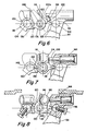
- Compound transmission 210 comprises a multiple speed main transmission section 212 connected in series with a range type auxiliary section 214.
- Transmission 210 is housed within a housing H and includes an input shaft 216 driven by a prime mover such as diesel engine E through a selectively disengaged, normally engaged friction master clutch C having an input or driving portion 218 drivingly connected to the engine crankshaft 220 and a driven portion 222 rotatably fixed to the transmission input shaft 216.
- a prime mover such as diesel engine E
- a selectively disengaged, normally engaged friction master clutch C having an input or driving portion 218 drivingly connected to the engine crankshaft 220 and a driven portion 222 rotatably fixed to the transmission input shaft 216.
- the input shaft 216 carries an input gear 224 for simultaneously driving a plurality of substantially identical countershaft assemblies 226 and 226A at substantially identical rotational speeds.
- the two substantially identical countershaft assemblies are provided on diametrically opposite sides of mainshaft 228 which is generally coaxially aligned with the input shaft 216.
- Each of the countershaft assemblies comprises a countershaft 230 supported by bearings 232 and 234 in housing H, only a portion of which is schematically illustrated.
- Each of the countershafts is provided with an identical grouping of countershaft gears 238, 240, 242, 244, 246 and 248, fixed for rotation therewith.
- a plurality of mainshaft gears 250, 252, 254, 256 and 258 surround the mainshaft 228 and are selectively clutchable, one at a time, to the mainshaft 228 for rotation therewith by sliding clutch collars 260, 262 and 264 as is well known in the prior art.
- Clutch collar 260 may also be utilized to clutch input gear 224 to mainshaft 228 to provide a direct drive relationship between input shaft 216 and mainshaft 228.
- clutch collars 260, 262 and 264 are axially positioned by means of shift forks 260A, 262A and 264A, respectively, associated with the shift housing assembly 270, as well known in the prior art, see U.S. Patent Nos. 4,502,346 and 4,543,843, the disclosures of which are incorporated by reference.
- Clutch collars 260, 262 and 264 may be of the well known acting synchronized or nonsynchronized double acting jaw clutch type.
- Mainshaft gear 258 is the reverse gear and is in continuous meshing engagement with countershaft gears 248 by means of conventional intermediate idler gears (not shown). It should also be noted that while main transmission section 212 does provide five selectable forward speed ratios, the lowest forward speed ratio, namely that provided by drivingly connecting mainshaft drive gear 256 to mainshaft 228, is often of such a high gear reduction it has to be considered a low or "creeper" gear which is utilized only for starting of a vehicle under severe conditions and, is not usually utilized in the high transmission range. Accordingly, while main transmission section 212 does provide five forward speeds, it is usually referred to as a "four plus one" main section as only four of the forward speeds are compounded by the auxiliary range transmission section 214 utilized therewith.
- Jaw clutches 260, 262, and 264 are three-position clutches in that they may be positioned in the centered, nonengaged position as illustrated, or in a fully rightwardly engaged or fully leftwardly engaged position by means of a shift lever 272. As is well known, only one of the clutches 260, 262 and 264 is engagable at a given time and main section interlock means are provided to lock the other clutches in the neutral condition.
- Auxiliary transmission range section 214 includes two substantially identical auxiliary countershaft assemblies 274 and 274A, each comprising an auxiliary countershaft 276 supported by bearings 278 and 280 in housing H and carrying two auxiliary section countershaft gears 282 and 284 for rotation therewith.
- Auxiliary countershaft gears 282 are constantly meshed with and support range/output gear 286 while auxiliary section countershaft gears 284 are constantly meshed with output gear 288 which is fixed to transmission output shaft 290.
- a two-position synchronized jaw clutch assembly 292 which is axially positioned by means of shift fork 294 and the range section shifting actuator assembly 296, is provided for clutching either gear 286 to mainshaft 228 for low range operation or gear 288 to mainshaft 228 for direct or high range operation of the compound transmission 210.
- the shift pattern for compound range type transmission 210 is schematically illustrated in Figure 12B. Selection of low or high range operation of the transmission 210 is by means of an operator actuated switch or button 298 which is usually located at the shift lever 272. Alternatively a "double H ⁇ type auxiliary shifting device may be utilized.
- the shift bar housing of transmission 212 is preferably provided with an interlock, which may comprise an interlock similar to interlock 108 illustrated in Figure 1, actuated by a resiliently compressible interlock plunger, see above-mentioned U.S. Patent No. 4,676,115, to provide the resilient range interlock function.
- an interlock which may comprise an interlock similar to interlock 108 illustrated in Figure 1, actuated by a resiliently compressible interlock plunger, see above-mentioned U.S. Patent No. 4,676,115, to provide the resilient range interlock function.
Landscapes
- Engineering & Computer Science (AREA)
- General Engineering & Computer Science (AREA)
- Mechanical Engineering (AREA)
- Gear-Shifting Mechanisms (AREA)
- Control Of Transmission Device (AREA)
- Structure Of Transmissions (AREA)
Applications Claiming Priority (2)
| Application Number | Priority Date | Filing Date | Title |
|---|---|---|---|
| US362786 | 1982-03-29 | ||
| US07/362,786 US4944197A (en) | 1989-06-07 | 1989-06-07 | Resilient range interlock |
Publications (3)
| Publication Number | Publication Date |
|---|---|
| EP0401514A2 true EP0401514A2 (de) | 1990-12-12 |
| EP0401514A3 EP0401514A3 (de) | 1991-11-06 |
| EP0401514B1 EP0401514B1 (de) | 1995-08-09 |
Family
ID=23427524
Family Applications (1)
| Application Number | Title | Priority Date | Filing Date |
|---|---|---|---|
| EP90108485A Expired - Lifetime EP0401514B1 (de) | 1989-06-07 | 1990-05-05 | Nachgiebige Schaltbereichsverriegelung |
Country Status (5)
| Country | Link |
|---|---|
| US (1) | US4944197A (de) |
| EP (1) | EP0401514B1 (de) |
| JP (1) | JP3023563B2 (de) |
| CA (1) | CA2016126C (de) |
| DE (1) | DE69021450T2 (de) |
Cited By (3)
| Publication number | Priority date | Publication date | Assignee | Title |
|---|---|---|---|---|
| EP0552870A1 (de) * | 1992-01-23 | 1993-07-28 | Eaton Corporation | Steuerungseinrichtung und -verfahren für eine Zusatzgetriebebetätigung |
| EP0552866A1 (de) * | 1992-01-23 | 1993-07-28 | Eaton Corporation | Mit veränderlichem Druck arbeitender Kolben für eine Zusatzgetriebebetätigung |
| DE10114557A1 (de) * | 2001-03-24 | 2002-09-26 | Zahnradfabrik Friedrichshafen | Fahrzeuggetriebe |
Families Citing this family (42)
| Publication number | Priority date | Publication date | Assignee | Title |
|---|---|---|---|---|
| US5199314A (en) * | 1992-01-23 | 1993-04-06 | Eaton Corporation | Synchronized splitter section protection system/method |
| US5218878A (en) * | 1992-01-23 | 1993-06-15 | Eaton Corporation | Two-stage range piston-cylinder assembly |
| US5199311A (en) * | 1992-01-23 | 1993-04-06 | Eaton Corporation | Variable pressure range section actuator assembly |
| US5199312A (en) * | 1992-01-23 | 1993-04-06 | Eaton Corporation | Range section actuator control system and method for preventing damage to range section synchronizers |
| US5172604A (en) * | 1992-01-23 | 1992-12-22 | Eaton Corporation | Range section preexhaust |
| US5216931A (en) * | 1992-01-23 | 1993-06-08 | Eaton Corporation | Interlock mechanism for range section slave valve |
| US5231895A (en) * | 1992-01-23 | 1993-08-03 | Eaton Corporation | Auxiliary section actuator air control system |
| US5186066A (en) * | 1992-01-23 | 1993-02-16 | Eaton Corporation | Dual pressure pressure regulator |
| US5222404A (en) * | 1992-01-23 | 1993-06-29 | Eaton Corporation | Auxiliary section actuator control system and method |
| US5435212A (en) * | 1992-10-30 | 1995-07-25 | Eaton Corporation | Semi-automatic shift implementation |
| US5398563A (en) * | 1993-05-14 | 1995-03-21 | Eaton Corporation | Compound transmission having four speed auxiliary construction |
| US5546823A (en) * | 1993-05-20 | 1996-08-20 | Eaton Corporation | High-capacity compound transmission |
| US5370013A (en) * | 1993-05-20 | 1994-12-06 | Eaton Corporation | Helically geared compound transmission |
| US5390561A (en) * | 1993-05-20 | 1995-02-21 | Eaton Corporation | Compound transmission |
| US5642643A (en) | 1994-11-28 | 1997-07-01 | Eaton Corporation | Reduced-length, high-capacity compound transmission |
| US5546825A (en) | 1994-12-13 | 1996-08-20 | Eaton Corporation | Change gear transmission and shift rod interlock therefor |
| US5676017A (en) * | 1995-07-27 | 1997-10-14 | Rockwell Heavy Vehicle Systems, Inc. | Automatic range shift for multi-speed transmission |
| US5582558A (en) * | 1995-07-27 | 1996-12-10 | Rockwell International Corporation | Combined system for assisting shifting of manual transmission |
| US5641044A (en) * | 1995-07-31 | 1997-06-24 | Eaton Corporation | Double-acting pin-type synchronizer assembly and synchronizer pin assembly |
| US5679096A (en) * | 1996-04-08 | 1997-10-21 | Eaton Corporation | Torque control for powertrain and change-gear transmission utilized in same |
| US5737978A (en) * | 1996-04-10 | 1998-04-14 | Eaton Corporation | Two-piece housing for compound transmission |
| US5682790A (en) | 1996-04-30 | 1997-11-04 | Eaton Corporation | Synchronizing and gear engagement sensing logic for automated mechanical transmission system |
| US5904068A (en) | 1996-04-30 | 1999-05-18 | Eaton Corporation | Semi-automatic shift implementation with synchronized transmission emulation |
| US5735771A (en) | 1996-04-30 | 1998-04-07 | Eaton Corporation | Semi-automatic shift implementation |
| EP0849502A3 (de) | 1996-08-05 | 1998-11-25 | Eaton Corporation | Getriebewelle und Methode zu deren Herstellung |
| US5904635A (en) | 1997-08-07 | 1999-05-18 | Eaton Corporation | Partially automated lever-shifted mechanical transmission system |
| US5907974A (en) * | 1998-04-29 | 1999-06-01 | Eaton Corporation | Splitter lockout system arranged for conversion between first and second owner configurations |
| US5992267A (en) | 1998-10-26 | 1999-11-30 | Eaton Corporation | Robust control for three-position transmission shift actuator assembly |
| US6193629B1 (en) * | 1999-05-07 | 2001-02-27 | Ford Global Technologies, Inc. | Shifting mechanism |
| US6165103A (en) * | 1999-05-07 | 2000-12-26 | Visteon Global Technologies, Inc. | Shifting mechanism |
| US6339973B1 (en) | 2000-04-10 | 2002-01-22 | Eaton Corporation | Slave valve with integral syncho-saver logic |
| FR2861446B1 (fr) * | 2003-10-22 | 2006-02-24 | Redex | Gamme de reducteurs de vitesse |
| US6997074B2 (en) | 2003-10-30 | 2006-02-14 | Eaton Corporation | Prediction of destination gear for progressive shift feature |
| US8635925B2 (en) * | 2004-11-22 | 2014-01-28 | Eaton Corporation | Transmission auxiliary unit shift inhibitor |
| AU2007358743B2 (en) * | 2007-09-14 | 2012-07-26 | Volvo Truck Corporation | Arrangement for inhibiting range shifting in a transmission |
| US8943922B2 (en) * | 2008-07-24 | 2015-02-03 | Deere & Company | Transmission creeper interlock |
| US8726749B2 (en) * | 2011-09-25 | 2014-05-20 | Eaton Corporation | Transmission overdrive yoke position sensor for range trigger |
| CN102817972B (zh) * | 2012-09-03 | 2015-02-18 | 江苏省无锡探矿机械总厂有限公司 | 紧凑型多档变速箱 |
| CN202834027U (zh) * | 2012-09-27 | 2013-03-27 | 陕西法士特齿轮有限责任公司 | 一种变速器操纵机构 |
| US9605753B2 (en) | 2015-08-06 | 2017-03-28 | Borgwarner Inc. | Speed-responsive mechanical range lock for a transfer case |
| US10495216B2 (en) | 2017-01-26 | 2019-12-03 | Kongsberg Automotive As | Interrocker assembly |
| RU209227U1 (ru) * | 2020-11-09 | 2022-02-08 | Открытое Акционерное Общество "Минский Завод Колёсных Тягачей" | Гидромеханическая передача транспортного средства большой мощности |
Family Cites Families (7)
| Publication number | Priority date | Publication date | Assignee | Title |
|---|---|---|---|---|
| US2654268A (en) * | 1951-07-14 | 1953-10-06 | Fuller Mfg Co | Shift control for auxiliary transmissions |
| US3229551A (en) * | 1963-06-10 | 1966-01-18 | Dana Corp | Shifting mechanism |
| FR2322307A1 (fr) * | 1975-09-01 | 1977-03-25 | Peugeot | Ensemble de transmission comportant une boite de vitesses principale en serie avec un relais au moins a deux rapports |
| US4388843A (en) * | 1980-11-21 | 1983-06-21 | Eaton Corporation | Auxiliary transmission neutral positioning and locking control and mechanism |
| US4409859A (en) * | 1981-04-30 | 1983-10-18 | Dana Corporation | Shift-rail interlock bracket for compound transmission |
| JPS60128519A (ja) * | 1983-12-16 | 1985-07-09 | Aisin Seiki Co Ltd | 変速機の操作機構 |
| US4974468A (en) * | 1989-02-16 | 1990-12-04 | Eaton Corporation | Compound transmission and shift control therefor |
-
1989
- 1989-06-07 US US07/362,786 patent/US4944197A/en not_active Expired - Lifetime
-
1990
- 1990-05-04 CA CA002016126A patent/CA2016126C/en not_active Expired - Fee Related
- 1990-05-05 DE DE69021450T patent/DE69021450T2/de not_active Expired - Fee Related
- 1990-05-05 EP EP90108485A patent/EP0401514B1/de not_active Expired - Lifetime
- 1990-06-07 JP JP2149704A patent/JP3023563B2/ja not_active Expired - Fee Related
Cited By (4)
| Publication number | Priority date | Publication date | Assignee | Title |
|---|---|---|---|---|
| EP0552870A1 (de) * | 1992-01-23 | 1993-07-28 | Eaton Corporation | Steuerungseinrichtung und -verfahren für eine Zusatzgetriebebetätigung |
| EP0552866A1 (de) * | 1992-01-23 | 1993-07-28 | Eaton Corporation | Mit veränderlichem Druck arbeitender Kolben für eine Zusatzgetriebebetätigung |
| TR27319A (tr) * | 1992-01-23 | 1995-01-12 | Eaton Corp | Yardimci bölüm isletici kontrol sistemi ve yöntemi. |
| DE10114557A1 (de) * | 2001-03-24 | 2002-09-26 | Zahnradfabrik Friedrichshafen | Fahrzeuggetriebe |
Also Published As
| Publication number | Publication date |
|---|---|
| JP3023563B2 (ja) | 2000-03-21 |
| CA2016126A1 (en) | 1990-12-07 |
| CA2016126C (en) | 1995-02-21 |
| EP0401514B1 (de) | 1995-08-09 |
| US4944197A (en) | 1990-07-31 |
| DE69021450T2 (de) | 1996-04-18 |
| DE69021450D1 (de) | 1995-09-14 |
| JPH03103672A (ja) | 1991-04-30 |
| EP0401514A3 (de) | 1991-11-06 |
Similar Documents
| Publication | Publication Date | Title |
|---|---|---|
| EP0401514B1 (de) | Nachgiebige Schaltbereichsverriegelung | |
| EP0383493B1 (de) | Verbundgetriebe und zugehörige Schaltsteuerung | |
| US5000060A (en) | Compound transmission and shift control therefor | |
| EP0395241B1 (de) | Schaltmechanismus mit einer einzigen Schaltstange | |
| EP0595496B1 (de) | Halbautomatische Schaltdurchführung | |
| EP0601741B1 (de) | Ruckschaltungs-Schutzvorrichtung | |
| EP0203732B1 (de) | Halbautomatisches Getriebe | |
| EP0309108B1 (de) | Bereichserweitertes Doppelverteilergetriebe | |
| EP0202800B1 (de) | Leistungssynchronisiereinrichtung | |
| US5737969A (en) | Single shaft shifting mechanism | |
| US5062313A (en) | Manual control for extended range splitter type compound transmission | |
| US5791189A (en) | Compound transmission with repeat or double-I shift pattern | |
| US5285694A (en) | Shift plate actuated single shaft shifting mechanism | |
| EP0317094B1 (de) | Handschaltung für Splitterverbundgetriebe mit erweitertem Schaltbereich | |
| US5893293A (en) | Single shaft shifting mechanism | |
| US5297453A (en) | Snap ring actuated single shaft shifting mechanism | |
| US4584895A (en) | Transmission shift control | |
| EP0389105A1 (de) | Handschaltung für Splitterverbundgetriebe mit erweitertem Schaltbereich | |
| EP0737828A1 (de) | Fahrzeuggetriebe | |
| EP0943845B1 (de) | Vorspannungseinrichtung für mechanisches Getriebe mit einer einzigen Schaltwelle | |
| US5398563A (en) | Compound transmission having four speed auxiliary construction |
Legal Events
| Date | Code | Title | Description |
|---|---|---|---|
| PUAI | Public reference made under article 153(3) epc to a published international application that has entered the european phase |
Free format text: ORIGINAL CODE: 0009012 |
|
| AK | Designated contracting states |
Kind code of ref document: A2 Designated state(s): DE FR GB IT SE |
|
| PUAL | Search report despatched |
Free format text: ORIGINAL CODE: 0009013 |
|
| AK | Designated contracting states |
Kind code of ref document: A3 Designated state(s): DE FR GB IT SE |
|
| RHK1 | Main classification (correction) |
Ipc: F16H 63/44 |
|
| 17P | Request for examination filed |
Effective date: 19920214 |
|
| 17Q | First examination report despatched |
Effective date: 19930126 |
|
| GRAA | (expected) grant |
Free format text: ORIGINAL CODE: 0009210 |
|
| AK | Designated contracting states |
Kind code of ref document: B1 Designated state(s): DE FR GB IT SE |
|
| REF | Corresponds to: |
Ref document number: 69021450 Country of ref document: DE Date of ref document: 19950914 |
|
| ET | Fr: translation filed | ||
| ITF | It: translation for a ep patent filed | ||
| PLBE | No opposition filed within time limit |
Free format text: ORIGINAL CODE: 0009261 |
|
| STAA | Information on the status of an ep patent application or granted ep patent |
Free format text: STATUS: NO OPPOSITION FILED WITHIN TIME LIMIT |
|
| 26N | No opposition filed | ||
| REG | Reference to a national code |
Ref country code: GB Ref legal event code: IF02 |
|
| PGFP | Annual fee paid to national office [announced via postgrant information from national office to epo] |
Ref country code: FR Payment date: 20050517 Year of fee payment: 16 |
|
| PGFP | Annual fee paid to national office [announced via postgrant information from national office to epo] |
Ref country code: IT Payment date: 20060531 Year of fee payment: 17 |
|
| REG | Reference to a national code |
Ref country code: FR Ref legal event code: ST Effective date: 20070131 |
|
| PG25 | Lapsed in a contracting state [announced via postgrant information from national office to epo] |
Ref country code: FR Free format text: LAPSE BECAUSE OF NON-PAYMENT OF DUE FEES Effective date: 20060531 |
|
| PGFP | Annual fee paid to national office [announced via postgrant information from national office to epo] |
Ref country code: DE Payment date: 20080530 Year of fee payment: 19 |
|
| PGFP | Annual fee paid to national office [announced via postgrant information from national office to epo] |
Ref country code: SE Payment date: 20080505 Year of fee payment: 19 |
|
| PGFP | Annual fee paid to national office [announced via postgrant information from national office to epo] |
Ref country code: GB Payment date: 20080407 Year of fee payment: 19 |
|
| PG25 | Lapsed in a contracting state [announced via postgrant information from national office to epo] |
Ref country code: IT Free format text: LAPSE BECAUSE OF NON-PAYMENT OF DUE FEES Effective date: 20070505 |
|
| GBPC | Gb: european patent ceased through non-payment of renewal fee |
Effective date: 20090505 |
|
| PG25 | Lapsed in a contracting state [announced via postgrant information from national office to epo] |
Ref country code: GB Free format text: LAPSE BECAUSE OF NON-PAYMENT OF DUE FEES Effective date: 20090505 |
|
| PG25 | Lapsed in a contracting state [announced via postgrant information from national office to epo] |
Ref country code: DE Free format text: LAPSE BECAUSE OF NON-PAYMENT OF DUE FEES Effective date: 20091201 |
|
| PG25 | Lapsed in a contracting state [announced via postgrant information from national office to epo] |
Ref country code: SE Free format text: LAPSE BECAUSE OF NON-PAYMENT OF DUE FEES Effective date: 20090506 |