EP0401531A2 - Battery powered vacuum cleaner - Google Patents
Battery powered vacuum cleaner Download PDFInfo
- Publication number
- EP0401531A2 EP0401531A2 EP90108735A EP90108735A EP0401531A2 EP 0401531 A2 EP0401531 A2 EP 0401531A2 EP 90108735 A EP90108735 A EP 90108735A EP 90108735 A EP90108735 A EP 90108735A EP 0401531 A2 EP0401531 A2 EP 0401531A2
- Authority
- EP
- European Patent Office
- Prior art keywords
- battery
- vacuum cleaner
- housing
- recess
- engaging unit
- Prior art date
- Legal status (The legal status is an assumption and is not a legal conclusion. Google has not performed a legal analysis and makes no representation as to the accuracy of the status listed.)
- Granted
Links
Images








Classifications
-
- A—HUMAN NECESSITIES
- A47—FURNITURE; DOMESTIC ARTICLES OR APPLIANCES; COFFEE MILLS; SPICE MILLS; SUCTION CLEANERS IN GENERAL
- A47L—DOMESTIC WASHING OR CLEANING; SUCTION CLEANERS IN GENERAL
- A47L9/00—Details or accessories of suction cleaners, e.g. mechanical means for controlling the suction or for effecting pulsating action; Storing devices specially adapted to suction cleaners or parts thereof; Carrying-vehicles specially adapted for suction cleaners
- A47L9/28—Installation of the electric equipment, e.g. adaptation or attachment to the suction cleaner; Controlling suction cleaners by electric means
- A47L9/2889—Safety or protection devices or systems, e.g. for prevention of motor over-heating or for protection of the user
-
- A—HUMAN NECESSITIES
- A47—FURNITURE; DOMESTIC ARTICLES OR APPLIANCES; COFFEE MILLS; SPICE MILLS; SUCTION CLEANERS IN GENERAL
- A47L—DOMESTIC WASHING OR CLEANING; SUCTION CLEANERS IN GENERAL
- A47L5/00—Structural features of suction cleaners
- A47L5/12—Structural features of suction cleaners with power-driven air-pumps or air-compressors, e.g. driven by motor vehicle engine vacuum
- A47L5/22—Structural features of suction cleaners with power-driven air-pumps or air-compressors, e.g. driven by motor vehicle engine vacuum with rotary fans
- A47L5/28—Suction cleaners with handles and nozzles fixed on the casings, e.g. wheeled suction cleaners with steering handle
- A47L5/30—Suction cleaners with handles and nozzles fixed on the casings, e.g. wheeled suction cleaners with steering handle with driven dust-loosening tools, e.g. rotating brushes
-
- A—HUMAN NECESSITIES
- A47—FURNITURE; DOMESTIC ARTICLES OR APPLIANCES; COFFEE MILLS; SPICE MILLS; SUCTION CLEANERS IN GENERAL
- A47L—DOMESTIC WASHING OR CLEANING; SUCTION CLEANERS IN GENERAL
- A47L9/00—Details or accessories of suction cleaners, e.g. mechanical means for controlling the suction or for effecting pulsating action; Storing devices specially adapted to suction cleaners or parts thereof; Carrying-vehicles specially adapted for suction cleaners
- A47L9/28—Installation of the electric equipment, e.g. adaptation or attachment to the suction cleaner; Controlling suction cleaners by electric means
- A47L9/2857—User input or output elements for control, e.g. buttons, switches or displays
-
- A—HUMAN NECESSITIES
- A47—FURNITURE; DOMESTIC ARTICLES OR APPLIANCES; COFFEE MILLS; SPICE MILLS; SUCTION CLEANERS IN GENERAL
- A47L—DOMESTIC WASHING OR CLEANING; SUCTION CLEANERS IN GENERAL
- A47L9/00—Details or accessories of suction cleaners, e.g. mechanical means for controlling the suction or for effecting pulsating action; Storing devices specially adapted to suction cleaners or parts thereof; Carrying-vehicles specially adapted for suction cleaners
- A47L9/28—Installation of the electric equipment, e.g. adaptation or attachment to the suction cleaner; Controlling suction cleaners by electric means
- A47L9/2868—Arrangements for power supply of vacuum cleaners or the accessories thereof
- A47L9/2884—Details of arrangements of batteries or their installation
-
- A—HUMAN NECESSITIES
- A47—FURNITURE; DOMESTIC ARTICLES OR APPLIANCES; COFFEE MILLS; SPICE MILLS; SUCTION CLEANERS IN GENERAL
- A47L—DOMESTIC WASHING OR CLEANING; SUCTION CLEANERS IN GENERAL
- A47L9/00—Details or accessories of suction cleaners, e.g. mechanical means for controlling the suction or for effecting pulsating action; Storing devices specially adapted to suction cleaners or parts thereof; Carrying-vehicles specially adapted for suction cleaners
- A47L9/28—Installation of the electric equipment, e.g. adaptation or attachment to the suction cleaner; Controlling suction cleaners by electric means
- A47L9/30—Arrangement of illuminating devices
-
- Y—GENERAL TAGGING OF NEW TECHNOLOGICAL DEVELOPMENTS; GENERAL TAGGING OF CROSS-SECTIONAL TECHNOLOGIES SPANNING OVER SEVERAL SECTIONS OF THE IPC; TECHNICAL SUBJECTS COVERED BY FORMER USPC CROSS-REFERENCE ART COLLECTIONS [XRACs] AND DIGESTS
- Y10—TECHNICAL SUBJECTS COVERED BY FORMER USPC
- Y10S—TECHNICAL SUBJECTS COVERED BY FORMER USPC CROSS-REFERENCE ART COLLECTIONS [XRACs] AND DIGESTS
- Y10S15/00—Brushing, scrubbing, and general cleaning
- Y10S15/01—Rechargeable batter
Definitions
- This invention relates to improvements in vacuum cleaners, and is more in particular directed to the provision of a battery powered upright vacuum cleaner.
- the present invention is therefor directed to the provision of an upright vacuum cleaner that overcomes the above disadvantages.
- a vacuum cleaner having a floor engaging unit and a handle assembly pivotally mounted thereto.
- the floor engaging unit includes a vacuum pump formed by a motor mounted to a base, the base having airflow ducts formed therein, for directing air from an inlet nozzle to an outlet tube.
- One or more lamps are provided within the floor engaging unit for directly light forwardly of the vacuum cleaner through a horizontally elongated lens.
- the lens has a front surface with horizontal grooves formed therein shaped to direct the light downwardly to a determined location in front of the vacuum cleaner.
- the handle assembly includes a housing pivoted to the floor engaging unit, and a handle extending from the opposite end thereof.
- a rigid or semirigid dirt tube extends longitudinally in one side of a recess in one side of the housing, and has a lower end coupled via a flexible tube to the outlet of the floor engaging unit.
- the flexible tube may be a separate tube or it may be formed integrally with the dirt tube, having thinner walls than the dirt tube to retain its flexibility.
- the dirt tube has a forwardly extending port in its other end to receive a disposable dust bag adapted to be removably assembled in the front recess.
- a removable cover covers the front recess to permit access to the dust bag.
- a further recess is provided in the rear of the housing for releasably receiving a rechargeable sealed lead acid battery assembly box, the battery being adapted to being recharged either attached to the vacuum cleaner or removed therefrom.
- the battery assembly box includes the battery, a recharging circuit including a recharging light, and a circuit breaker that is accessible at the rear of the vacuum cleaner for being manually reset.
- a control board is provided at the upper end of the housing, including a switch enabling operation of the machine either with or without use of the lights.
- An indicator such as a row of LEDs is also provided on the control board, to indicate the charge condition of the batter to the user.
- a vacuum cleaner in accordance with the invention is comprised of a floor engaging unit 100 which encloses the vacuum cleaner motor as will be discussed.
- the unit 100 is provided with a pair of rear wheels 101, a lever 102 for enabling the latching of the handle assembly in desired positions, and a hood 103.
- the vacuum cleaner further includes a handle assembly 200 pivotally mounted to the rear of the floor engaging unit 100, the handle assembly including a housing 201 whose lower end is pivoted to the floor engaging unit, a handle 202 extending from the opposite end of the canister, and a hand grip 203 preferable shaped to enable a user to comfortably grip this element.
- the housing 201 has a body portion 204 at the rear side thereof, the front of the housing including a bottom front cover 205 and a removable upper front cover 206.
- the lip 211 preferably projects rearwardly of the body a sufficient distance that, when the vacuum cleaner is on a floor and the handle assembly is positioned horizontally, the lip 211 will engage the surface of the floor to prevent the handle 202 and grip 203 pressing against the floor. This feature minimizes danger of damage to the handle assembly by stressing the handle.
- the rear of the body 204 includes a recess 208 for receiving a battery assembly 300, vents 209 for venting air from the housing and a recess 210 at the upper portion thereof, having an upper lip 211, to facilitate carrying of the vacuum cleaner.
- Fig. 2 also shows the latch 212 permitting release of the battery assembly.
- Figs. 1 and 2 illustrate the handle assembly of the vacuum cleaner in an upright position.
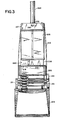
- Fig. 3 illustrates the vacuum cleaner with the handle assembly in a generally horizontal position, with the upper front cover removed, to show a porous bag 215 fit therein.
- the upper front cover of the vacuum cleaner is readily removable by the user to permit changing of the bag.
- the front cover 206 may be removably held to the housing 204 by any convenient means.
- the cover 206 may have downwardly extending projections (not illustrated) engagable with apertures 216 at the top of the bottom cover 205.
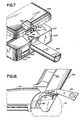
- the top of the front cover 206 may be held by an internal projection positioned to enter the slot 216 in a handle folding assembly plate 217 affixed to the top of the housing, as seen in Fig. 7, with a spring loaded button 218 at the top of the housing engaging the projection in the upper position of the button.
- Fig. 4 illustrates the vacuum cleaner in the same position as Fig. 3, but in this figure the lower cover 205 and hood 103 have also been removed, the upper portion being partially in section, and the housing is illustrated without the porous bag 215.
- a base 105 supports on its top surface a motor 106 with a vertical shaft.
- the motor 106 rotates a fan (not illustrated in Fig. 4), to exhaust air by way of a duct 107 formed in the base 105.
- the rear end of the duct is connected to a flexible tube 108, the other end of the tube 108 joining one end of the dirt tube 220 mounted in the body portion of the housing 201.
- the dirt tube 220 extends along one side 221 of the housing, with the other end thereof having a forwardly directed port 222 with a cylindrical extension 224 for receiving the porous bag 215 of Fig. 3.
- the inter-connection between the porous bag and the cylindrical extension 224 may be conventional.
- the dirt tube for example of a rigid plastic material, may be separately formed from the flexible tube 108, it is advantageous that these elements be formed as a single plastic unit. In this event the necessary flexibility of the tube 108 may be obtained by decreasing the wall thickness in this part of the combined structure. Decreased wall thickness does not incur any risk of collapse of the tube since the tube is under positive pressure in use.
- the upper end of the dirt tube 220 may have a projection 225 adapted to be held by the plate 217 of Fig. 3.
- Air vents 226 are provided in the rear wall of the body portion 204 laterally of the dirt tube 220, at the upper end of the body portion 204.
- a battery receptacle 230 is provided laterally of the dirt tube in the lower region of the body portion, the battery receptacle 230 being formed in the body portion 204 and being opened rearwardly of the body portion, as will be discussed.
- Spring fingers 231 of a latch for holding the batteryassembly are visible in this view of the housing.
- a pair of spring contact fingers 232 are mounted adjacent the bottom of the receptacle 230, at fixed positions 233, to interconnect the terminals of the battery assebmly with the internal components of the vacuum cleaner.
- the contact fingers 232 are connected by way of leads 235 to a control board 236 mounted at the upper end of the body portion 204, and the contact fingers 232 are connected by leads extending through a flexible conduit 237 to the motor 106 and lamps 238 in the floor engaging unit 100.
- the conduit 237 may be held to the base 105 by a clamp molded on the base 105.
- the dirt tube 220 has a lateral flange 220A internally of the housing, and spaced from the rear wall 201A of the housing.
- This flange in combination with suitable walls extending from the rear wall of the housing, defines a channel 201C through which the leads extend from the connectors 232 to the control board 236.
- the side wall 230A of the receptacle 230 and additional short walls 201B are laterally spaced apart to define the channel 201C, the channel being covered by the flange 220A.
- the dirt tube thus serves the additional function of defining part of the channel 201C for protecting the leads as they extend through the housing.
- a spiral duct 120 is also formed in the bottom of the base 105, forming part of the duct 107, for connection to the flexible tube 108.
- the bottom cover 125 has a rearward extension 126 aligned with the axis of the motor, and is releasably held to the base 105 by a pair of catches 127.
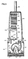
- the forward portion of the bottom cover 125 is provided with apertures 130 for receiving dust laden air, Fig. 5 illustrating a portion of a conventional brush roller 131 through the apertures 130.
- the front of the cover 125 may be held to the base by projections 132.
- a pair of front wheels 135 may be mounted to the under side of the base 105, rearwardly of the apertures 130 and laterally of the extension 126.
- the battery assembly 300 has a charging socket 301 on its rear side for receiving an electric plug for charging the batteries within the battery assembly.
- the battery assembly may also have a circuit breaker button 302, and an LED 303 for indicating that the battery is being charged.
- the shaft 140 of the motor is visible, the shaft carrying a pulley 141.
- the belt 142 extending around the pulley extends forwardly around the brush roller 131 in conventional manner, to rotate the brush roller during operation of the vacuum cleaner.
- the fan 143 is also visible in this view, the fan directing air from the region of the dust roller upwardly into the duct 120 for carrying dust to the dust bag 215 of Fig. 3.
- Fig. 6 also shows the recess 208 with the battery assembly removed.
- the contact fingers 232 which extend into the recess 208, are visible at the bottom of the recess.
- a pair of projections 250 are molded to extend laterally into the recess 208, near the lower end thereof, to enable installing the battery assembly in the recess.
- the button 218 is illustrated as affixed to a resilient plate 255 held in a slot within the cover 206.
- the button 218 extends through an aperture in the upper end of the cover 206, and carries a latch plate 256 having an enlarged end 257 adapted to be received in the slot 216 of the body portion 204.
- the enlarged end 257 hence catches under the plate 217 to hold the cover 206 against the body portion 204, being releasable by depression of the button 218 to permit separation of these members.
- control circuit board 203 includes a switch 258 for controlling the operation of the vacuum cleaner, as well as a plurality of indicators such as LEDs 259 for indicating the operating condition of the cleaner.
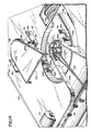
- Figs. 8 and 8A are alternate perspective views of a front corner of the floor engaging unit, partially in section, with the cover removed.
- the lamp 138 is of the cylindrical type, for example an automotive lamp, having terminals 151 at opposite ends thereof received in metal clips 152.
- the clips 152 have U-shaped brackets 153 fit over post 154 molded to the base 105, the brackets 153 being shaped to be held to the post 154.
- the brackets 153 carry connectors 155,155′ adapted to receive and contact the wires 156 in cable 237, in order to facilitate the wiring of the vacuum cleaner.
- the lamps may be controlled at selective positions of the switch 258 of Fig. 7. While one lamp is illustrated in Fig. 8, it is apparent that a further lamp is mounted in a similar manner on the other side of the base, as illustrated in Fig. 4.
- the mounting of the lamp as illustrated in Fig. 8, is relatively close to the base 105, in order to eliminate the necessity for increase in the height of the floor engaging unit due to the provision of the lamps.
- the lamps 138 are horizontally mounted, with light being directed to an elongated lens 160 mounted to the floor engaging unit forwardly of the lamp.
- the lens 160 as illustrated in Figs. 4 and 8-12, extends for substantially the width of the floor engaging unit, and has a front inclined portion 161 joined to a substantially horizontal upper portion 162.
- a projection 163 centrally of the lens has a slot 164 for receiving a mounting screw 165 or the like (Fig. 4), for holding the lens to a post or the like extending from the base 105.
- the lower portion of the lens is held by a lip 166 extending downwardly from the inclined portion 161, for example to engage a base strip 167 extending around the base 105 as illustrated in Fig. 8.
- the lens 160 is formed of a transparent plastic material, and the front of the inclined portion 161 is formed with horizontally extending light deflecting grooves 168. As illustrated in Figs. 11 and 12, the lamps 138 are positioned at substantially the same height as the top edge lens portion, to direct light into the upper rear edge of thelens.
- the grooves 168 are shaped to intercept this light and direct it to follow an inclined path to the floor upon which the floor engaging unit rests, for example several feet in front of the floor engaging unit.
- the lens was of a polycarbonate material, about 0.1 inches thick.
- the grooves were about 0.045 inches deep, having a bottom angle between the sides of 45 degrees, with the bottom sides of the grooves being at an angle of about 15 degrees to the horizontal.
- the overall height of the grooved front face of the lens was about 1/2 inches.
- FIGs. 13-15 illustrate in greater detail the latching arrangement in accordance with the invention for holding the bottom plate 125 to the base.
- a wall 155 molded to the base 105 extends downwardly therefrom, having a rear portion surrounding the rear of the aperture 156 through which the shaft of the motor extends, the bottom of the wall being shaped to conform to the outline of the bottom cover 125.
- the aperture 156 is thus in the bottom wall of the duct 120, wherein the fan 143 rotates, so that the fan draws dust laden air from the nozzle of the vacuum cleaner into the duct via the aperture.
- the sides of the rear extension 126 of the bottom cover 125 are provided with a pair of laterally extending projections having horizontal portions 157 depending from the rim of the extension and downwardly extending end portions 158.
- the end portions 158 carry a pair of catch projections 159 directed away from the extension, and adapted to be received in the apertures 160 in posts 161 extending downwardly from the base 105.
- the projections 157,158 are flexible, being molded with the plastic bottom cover 125, and are resiliently held with their projections 159 within the holes 160. Release of the rear of the bottom cover may be effected in a simple manner by grasping the planar central sections of the end portions 158 between the thumb and fingers and squeezing, while pulling the bottom cover away from the vacuum cleaner.
- Support walls 162 may be provided behind the end portions 157, and spaced therefrom, in order to limit the permissible displacement of the end portions 157.
- Figs. 16-18 illustrate the latching arrangement, in accordance with the invention, for enabling the handle assembly to be positioned at selected angles with respect to the horizontal.
- an arcuate cam projection 260 is provided on one side of the handle assembly, about 1.5 inches in radius. centered generally on the pivotal axis of the handle assembly.
- This cam surface is provided with a pair of steps 261, 262 for engaging a tab 169 of the latching leverf 170 at different angular displacements of the handle assembly.
- One end 171 of the latching lever is adapted to be pivotally mounted to a suitable wall of the base 105 forwardly of the pivotal axis of the handle assembly 200, for example at the hole 172.
- the other end 173 of the lever 170 is adapted to receive a suitable knob or the like for manipulation by the user.
- the lever 170 and cam surface 260 are preferably positioned at the left side of the vacuum cleaner, and the lever is resiliently biased for rotation in a counter-clockwise direction, as seen in Fig. 17, by any suitable means such as a helical spring 174 extending between a projection 175 on the lever and a fixed position on the base.
- the resilient bias urges the tab 169 toward the cam surface, to thereby prevent pivotal movement of the handle assembly in the clockwise direction when the tab engages one of the stop surfaces 261, 262.
- the restraining of the pivoting of the handle assembly is overcome by depression of the end 173 of the lever.
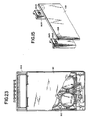
- the battery assembly in accordance with the invention is more clearly illustrated in Figs. 19-23, and is comprised of a box having a rear receptacle 310 joined to a front receptacle 311, for enclosing a battery 312.
- the battery is preferably a sealed rechargeable lead acid battery, for example a 12 volt 5.0 AH battery 8805 manufactured by Gates Energy Products, Inc.
- the sides of the rear receptacle 310, at one end thereof, are provided with recesses 313 extending from the rear surface, for receiving the projects 250 in the sides of the battery recess 208 of the housing 201.
- An extension 314 at the other end of the rear receptacle 310 defines a handle as well as a latch retainer for holding the battery assembly 300 within the recess or the housing 201.
- the front receptacle is provided with a step 320 at the lower end thereof, and a pair of battery contacts 321 extend through corresponding apertures in the forwardly facing surface of the step 320 to contact the contacts 232 when the battery assembly is installed.
- the step 320 serves to inhibit accidental shorting of the battery contacts 321, and thereby discharge of the battery, upon laying of the battery assembly down on a surface.
- the contacts 321 are connected to a circuit board 322 mounted within the rear and front receptacles 310, 311.
- the front and rear receptacles may be held together by any conventional technique.
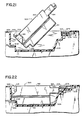
- Fig. 21 The installation of the battery assembly within the recess is illustrated in Fig. 21, wherein it is seen that the battery is initially held in a slanted position in order to engage the projections in the recesses 313. Using the projects as a pivot, the battery assembly is then pivoted until it is fully received in the recess 208 of the housing 201. The battery assembly is held in place by the latch 212 which is resiliently urged downwardly behind the end of the handle extension 314, as seen in Fig. 22.
- the rear receptacle has a pair of apertures for exposing a charge light 330 and the manual reset button of a circuit breaker 331, as well as a socket 332 for receiving a recharging plug.
- the latch 212 has a body portion 270 with a lateral guide projection 271 adapted to be received in suitable guide slots (not shown) in the housing 201 for guiding the latch toward and away from the battery assembly.
- a pair of spring fingers 231 depend from opposite sides of the top of the body portion 270 to extend through a recess in the housing 201, as seen in Fig. 4. The sides of the spring fingers 231 resiliently engage the sides of the recess through which they extend, to bias the latch 212 toward the battery assembly.
- the latch may be held to the housing 201 for limited by a projection 274 on the housing received in a recess 272 in the front of the latch, i.e. the side toward the housing.
- the rear of the latch may be provided with a recess 273 to enable the user to retract the latch for removal of the battery assembly.
- Figs. 26 and 27 illustrate the contacts 232 for engaging the battery assembly contacts 321.
- These contacts 232 which may be of a berylium copper alloy, are provided with a button 280 adapted to extend through a recess in the wall of the housing 201, to project resiliently into the recess 208.
- the contacts have a mounting hole 281 for mounting to the interior of the housing 201, the contacts being shaped between the hole 281 and button 280 to linearize the deflection of the button upon being contacted by the corresponding battery contact.
- the other end of the contact 232 is shaped as a spade connector 282 to facilitate the interconnection of the connector 232 and the circuitry within the vacuum cleaner.
- the circuit provided within the battery assembly 300 is illustrated in Fig. 28, wherein it is seen that the terminals 320 of the battery 312 are connected to the contacts 321 via the circuit breaker 331.
- the socket 332 is connected to the battery 312 via a charging rectifier 340, for charging the battery.
- the charging voltage is applied to the charge indicator LED 330 via a diode 341 and resistor 342. It is to be noted that the battery may be charged either while it is positioned within the recess 208 of the vacuum cleaner, or it may be removed for such charging.
- the circuit breaker 331 protects the battery 312 from short circuits.
- a step down transformer 350 may be provided having a secondary winding connected to a suitable plug 351 for being received by the socket 332, and a primary winding connected to a mains plug 352.
- Fig. 29 illustrates the circuit provided on the control board 236.
- the input terminals 285, connected to the connectors 232 are connected to the center contact of the two sections of the control switch 258.
- This switch has an OFF position, a position in which just the motor in the ground engaging unit is on, and a position in which both the motor and the lamps are on. The central position is thus useful to save current from the battery, so that the vacuum cleaner may operate for a longer time between recharging.
- the two ON contact positions of the lower switch section are connected to the coil of a relay 286, as well as to the center terminal of one relay contact 287.
- One ON contact of the upper switch section is connected to the circuit of the lamps.
- the relay is selected to release when the voltage applied to its coil falls below about 8.5 to 9.0 volts, in order to disconnect the battery from the motor and lamps in sufficient time to avoid a deep discharge of the battery that would affect the reliability of the battery.
- the contacts 287 apply the battery voltage to the vacuum cleaner motor as well as to an LED driver circuit 289 for energizing the LEDs 259.
- the driver circuit 289 comprises a voltmeter circuit, for selectively energizing the LEDs 259 in dependence upon the battery voltage. Since the terminal voltage of the battery is a function of the charge state, the parameters of the driver circuit 289 may be set in conventional manner to indicate determined discharge states of the battery, such as, for example, 4/5 capacity remaining, 3/5 capacity remaining, etc. In a preferred embodiment of the invention, five LEDs 259 are provided to indicate five different charge conditions. Alternatively the energizing of the lamps may be an indication of operating time remaining.
- the wheel assembly 101 for the rear wheel is comprised of a wheel 400 of rigid plastic, and a wheel cover 401 for example of flexible plastic.
- the wheel has a hub 402, an outer rim 403, a web 404 extending between the hub and the rim, and a plurality of radial internal strengthening fins 405.
- a parallel walled channel 406 extend from one edge to the center of the wheel, in which the web surface is depressed.
- the end 407 of the hub 402 toward the web is recessed, such that a gap 408 is defined at the inner end of the channel 406.
- the wheel cover has a circular web 419 with an outer rim 420.
- the edge of the rim is bent under to define a lip 421 adapted to engage under the edge of the rim 403 of the wheel to firmly hold the wheel cover on the wheel.
- the web 419 of the wheel cover 401 has a hinged tab 421 partially severed therefrom, but remaining affixed to the wheel cover at its outer radial extremity.
- the tab 421 is shaped generally the same as the channel 406, and the wheel cover is affixed to the wheel with the tab aligned with the channel.
- the radially inner end of the tab has a catch projection 430 adapted to extend through the gap 408 when the wheel cover is mounted on the wheel, the projection 430 thus having an outer surface 431 adapted to engage the inner surface 432 of the web 404 adjacent the end of the channel, to hold the tab against the wheel.
- the tab 425 is deformed to release the catch 430, and the tab is then hinged back.
- a suitable axle such as a mounting pin (not shown) is then inserted in the hole of the hub, with the head thereof engaging the emd 407 of the hub. (The internal end of the pin may be affixed to the vacuum cleaner by any conventional means).
- the tab 425 is then returned to the channel and bent until the catch again engages the under surface 432 of the web 404. The tab thus serves to hide the mounting arrangement of the wheel in a simple manner while presenting a pleasing external appearance.
Landscapes
- Engineering & Computer Science (AREA)
- Mechanical Engineering (AREA)
- Electric Vacuum Cleaner (AREA)
- Electric Suction Cleaners (AREA)
Abstract
Description
- This invention relates to improvements in vacuum cleaners, and is more in particular directed to the provision of a battery powered upright vacuum cleaner.
- In the past it has been common to provide portable vacuum cleaners with batteries. This technique has not been successfully employed in upright cleaner of the type having a handle assembly pivotted to a floor engaging unit, however, such vacuum cleaners hence conventionally requiring the interconnection of the cleaner with the power mains during use. While upright vacuum cleaners have many advantages, such as greater cleaning power, this interconnection creates problems in the use of the cleaner since it limits the distance that the cleaner may be used from an outlet, and the interconnecting cord tends to become tangled with furniture or the like during use.
- The present invention is therefor directed to the provision of an upright vacuum cleaner that overcomes the above disadvantages.
- Briefly stated, in accordance with the invention, a vacuum cleaner is provided having a floor engaging unit and a handle assembly pivotally mounted thereto.
- The floor engaging unit includes a vacuum pump formed by a motor mounted to a base, the base having airflow ducts formed therein, for directing air from an inlet nozzle to an outlet tube. One or more lamps are provided within the floor engaging unit for directly light forwardly of the vacuum cleaner through a horizontally elongated lens. The lens has a front surface with horizontal grooves formed therein shaped to direct the light downwardly to a determined location in front of the vacuum cleaner.
- The handle assembly includes a housing pivoted to the floor engaging unit, and a handle extending from the opposite end thereof. A rigid or semirigid dirt tube extends longitudinally in one side of a recess in one side of the housing, and has a lower end coupled via a flexible tube to the outlet of the floor engaging unit. The flexible tube may be a separate tube or it may be formed integrally with the dirt tube, having thinner walls than the dirt tube to retain its flexibility. The dirt tube has a forwardly extending port in its other end to receive a disposable dust bag adapted to be removably assembled in the front recess. A removable cover covers the front recess to permit access to the dust bag.
- A further recess is provided in the rear of the housing for releasably receiving a rechargeable sealed lead acid battery assembly box, the battery being adapted to being recharged either attached to the vacuum cleaner or removed therefrom. The battery assembly box includes the battery, a recharging circuit including a recharging light, and a circuit breaker that is accessible at the rear of the vacuum cleaner for being manually reset.
- A control board is provided at the upper end of the housing, including a switch enabling operation of the machine either with or without use of the lights. An indicator, such as a row of LEDs is also provided on the control board, to indicate the charge condition of the batter to the user.
- In order that the invention may be more clearly understood, it will now be disclosed in greater detail with reference to the accompanying drawing, wherein:
- Fig. 1 is a perspective view of a vacuum cleaner in accordance with the invention;
- Fig. 2 is a rear view of the vacuum cleaner of Fig. 1;
- Fig. 3 is a front plan view of the vacuum cleaner of Fig. 1, with the front cover removed;
- Fig. 4 is a front plan view in accordance with Fig. 3, with the hood and bottom front covers also removed;
- Fig. 4A is a cross sectional view of the dirt tube (only) taken along the
line 4A-4A of Fig. 4; - Fig. 4B is a cross sectional view of the dirt tube and a part of the housing taken along the
line 4B-4B of Fig. 4; - Fig. 5 is a rear plan view of the vacuum cleaner
- Fig. 6 is a rear plan view in accordance with Fig. 5, with the bottom cover and battery assembly removed;
- Fig. 7 is an enlarged perspective view of a portion of the handle assembly with the front cover partially opened;
- Figs. 8 and 8A are alternate enlarged perspective views of a portion of the floor engaging unit with the hood removed;
- Fig. 9 is a front view of the lens of the floor engaging unit;
- Fig. 10 is a top view of the lens of Fig. 9;
- Fig. 11 is a cross sectional view of the lens of Fig. 9 taken along the lines 11-11;
- Fig. 12 is an end view of the lens of Fig. 9;
- Fig. 13 is a bottom view of the bottom cover of the floor engaging unit;
- Fig. 14 is an enlarged perspective exploded view of a portion of the bottom of the floor engaging unit illustrating the latch arrangement for the bottom cover;
- Fig. 15 is an enlarged perspective view of a portion of the arrangement of Fig. 14, illustrating the latch disengagement;
- Fig. 16 is a view illustrating the handle assembly latching arrangement of the invention;
- Fig. 17 is a side view of the handle assembly position latch;
- Fig. 18 is an edge view of the latch of Fig. 24;
- Fig. 19 is a front view of the battery assembly;
- Fig. 20 is a side view of the battery assembly;
- Fig. 21 is an enlarged cross sectional view of a portion of the handle assembly and illustrating the procedure for installing the battery assembly;
- Fig. 22 is a view according to Fig. 21 illustrating the battery assembly in its installed position;
- Fig. 23 is a partially sectional front view of the battery assembly illustrating the battery and internal circuit board therein;
- Fig. 24 is a side view of the battery assembly latch;
- Fig. 25 is a cross sectional view of the latch of Fig. 24;
- Fig. 26 is a front view of a battery contact finger;
- Fig. 27 is a side view of the battery contact finger of Fig. 26
- Fig. 28 is a circuit diagram of the circuit within the battery assembly;
- Fig. 29 is a circuit diagram of the control circuit board of the vacuum cleaner;
- Fig. 30 is a side view of the wheel assembly; and
- Fig. 31 is an exploded cross sectional view of the wheel assembly.
- As illustrated in Fig. 1, the preferred embodiment of a vacuum cleaner in accordance with the invention is comprised of a
floor engaging unit 100 which encloses the vacuum cleaner motor as will be discussed. Theunit 100 is provided with a pair ofrear wheels 101, alever 102 for enabling the latching of the handle assembly in desired positions, and ahood 103. The vacuum cleaner further includes ahandle assembly 200 pivotally mounted to the rear of thefloor engaging unit 100, the handle assembly including ahousing 201 whose lower end is pivoted to the floor engaging unit, ahandle 202 extending from the opposite end of the canister, and ahand grip 203 preferable shaped to enable a user to comfortably grip this element. Thehousing 201 has abody portion 204 at the rear side thereof, the front of the housing including abottom front cover 205 and a removableupper front cover 206. Thelip 211 preferably projects rearwardly of the body a sufficient distance that, when the vacuum cleaner is on a floor and the handle assembly is positioned horizontally, thelip 211 will engage the surface of the floor to prevent thehandle 202 andgrip 203 pressing against the floor. This feature minimizes danger of damage to the handle assembly by stressing the handle. - As illustrated in Fig. 2, showing a rear view of the vacuum in Fig. 1, the rear of the
body 204 includes arecess 208 for receiving abattery assembly 300,vents 209 for venting air from the housing and arecess 210 at the upper portion thereof, having anupper lip 211, to facilitate carrying of the vacuum cleaner. Fig. 2 also shows thelatch 212 permitting release of the battery assembly. - Figs. 1 and 2 illustrate the handle assembly of the vacuum cleaner in an upright position. Fig. 3 illustrates the vacuum cleaner with the handle assembly in a generally horizontal position, with the upper front cover removed, to show a
porous bag 215 fit therein. The upper front cover of the vacuum cleaner is readily removable by the user to permit changing of the bag. Thefront cover 206 may be removably held to thehousing 204 by any convenient means. For example, thecover 206 may have downwardly extending projections (not illustrated) engagable withapertures 216 at the top of thebottom cover 205. The top of thefront cover 206 may be held by an internal projection positioned to enter theslot 216 in a handle foldingassembly plate 217 affixed to the top of the housing, as seen in Fig. 7, with a spring loadedbutton 218 at the top of the housing engaging the projection in the upper position of the button. - Fig. 4 illustrates the vacuum cleaner in the same position as Fig. 3, but in this figure the
lower cover 205 andhood 103 have also been removed, the upper portion being partially in section, and the housing is illustrated without theporous bag 215. - As illustrated in Fig. 4, a
base 105, molded for example from a plastic material, supports on its top surface amotor 106 with a vertical shaft. Themotor 106 rotates a fan (not illustrated in Fig. 4), to exhaust air by way of aduct 107 formed in thebase 105. The rear end of the duct is connected to aflexible tube 108, the other end of thetube 108 joining one end of thedirt tube 220 mounted in the body portion of thehousing 201. Thedirt tube 220 extends along oneside 221 of the housing, with the other end thereof having a forwardly directedport 222 with acylindrical extension 224 for receiving theporous bag 215 of Fig. 3. The inter-connection between the porous bag and thecylindrical extension 224 may be conventional. While the dirt tube, for example of a rigid plastic material, may be separately formed from theflexible tube 108, it is advantageous that these elements be formed as a single plastic unit. In this event the necessary flexibility of thetube 108 may be obtained by decreasing the wall thickness in this part of the combined structure. Decreased wall thickness does not incur any risk of collapse of the tube since the tube is under positive pressure in use. The upper end of thedirt tube 220 may have aprojection 225 adapted to be held by theplate 217 of Fig. 3. - Air vents 226 are provided in the rear wall of the
body portion 204 laterally of thedirt tube 220, at the upper end of thebody portion 204. Abattery receptacle 230 is provided laterally of the dirt tube in the lower region of the body portion, thebattery receptacle 230 being formed in thebody portion 204 and being opened rearwardly of the body portion, as will be discussed.Spring fingers 231 of a latch for holding the batteryassembly are visible in this view of the housing. A pair ofspring contact fingers 232 are mounted adjacent the bottom of thereceptacle 230, atfixed positions 233, to interconnect the terminals of the battery assebmly with the internal components of the vacuum cleaner. Thus, thecontact fingers 232 are connected by way ofleads 235 to acontrol board 236 mounted at the upper end of thebody portion 204, and thecontact fingers 232 are connected by leads extending through aflexible conduit 237 to themotor 106 and lamps 238 in thefloor engaging unit 100. Theconduit 237 may be held to thebase 105 by a clamp molded on thebase 105. - As illustrated in Figs. 4, 4A and 4B, the
dirt tube 220 has alateral flange 220A internally of the housing, and spaced from therear wall 201A of the housing. This flange, in combination with suitable walls extending from the rear wall of the housing, defines achannel 201C through which the leads extend from theconnectors 232 to thecontrol board 236. For example, as seen in Fig. 4B, theside wall 230A of thereceptacle 230 and additionalshort walls 201B are laterally spaced apart to define thechannel 201C, the channel being covered by theflange 220A. The dirt tube thus serves the additional function of defining part of thechannel 201C for protecting the leads as they extend through the housing. - As illustrated more clearly in Fig. 5, a
spiral duct 120 is also formed in the bottom of thebase 105, forming part of theduct 107, for connection to theflexible tube 108. Thebottom cover 125 has arearward extension 126 aligned with the axis of the motor, and is releasably held to thebase 105 by a pair ofcatches 127. The forward portion of thebottom cover 125 is provided withapertures 130 for receiving dust laden air, Fig. 5 illustrating a portion of aconventional brush roller 131 through theapertures 130. The front of thecover 125 may be held to the base byprojections 132. A pair offront wheels 135 may be mounted to the under side of thebase 105, rearwardly of theapertures 130 and laterally of theextension 126. - The
battery assembly 300 has a chargingsocket 301 on its rear side for receiving an electric plug for charging the batteries within the battery assembly. The battery assembly may also have a circuit breaker button 302, and anLED 303 for indicating that the battery is being charged. - As illustrated in Fig. 6, with the
bottom cover 125 of Fig. 5 removed, theshaft 140 of the motor is visible, the shaft carrying apulley 141. Thebelt 142 extending around the pulley extends forwardly around thebrush roller 131 in conventional manner, to rotate the brush roller during operation of the vacuum cleaner. Thefan 143 is also visible in this view, the fan directing air from the region of the dust roller upwardly into theduct 120 for carrying dust to thedust bag 215 of Fig. 3. - Fig. 6 also shows the
recess 208 with the battery assembly removed. In this view thecontact fingers 232, which extend into therecess 208, are visible at the bottom of the recess. In addition, a pair ofprojections 250 are molded to extend laterally into therecess 208, near the lower end thereof, to enable installing the battery assembly in the recess. - As illustrated in Fig. 7, wherein the upper end of the removable
front cover 206 is illustrated spaced from thebody portion 204, thebutton 218 is illustrated as affixed to aresilient plate 255 held in a slot within thecover 206. Thebutton 218 extends through an aperture in the upper end of thecover 206, and carries alatch plate 256 having anenlarged end 257 adapted to be received in theslot 216 of thebody portion 204. Theenlarged end 257 hence catches under theplate 217 to hold thecover 206 against thebody portion 204, being releasable by depression of thebutton 218 to permit separation of these members. - As further illustrated in Fig. 7, the
control circuit board 203 includes aswitch 258 for controlling the operation of the vacuum cleaner, as well as a plurality of indicators such asLEDs 259 for indicating the operating condition of the cleaner. - Figs. 8 and 8A are alternate perspective views of a front corner of the floor engaging unit, partially in section, with the cover removed. As illustrated, the
lamp 138 is of the cylindrical type, for example an automotive lamp, havingterminals 151 at opposite ends thereof received in metal clips 152. Theclips 152 haveU-shaped brackets 153 fit overpost 154 molded to thebase 105, thebrackets 153 being shaped to be held to thepost 154. Thebrackets 153 carry connectors 155,155′ adapted to receive and contact thewires 156 incable 237, in order to facilitate the wiring of the vacuum cleaner. The lamps may be controlled at selective positions of theswitch 258 of Fig. 7. While one lamp is illustrated in Fig. 8, it is apparent that a further lamp is mounted in a similar manner on the other side of the base, as illustrated in Fig. 4. - The mounting of the lamp as illustrated in Fig. 8, is relatively close to the
base 105, in order to eliminate the necessity for increase in the height of the floor engaging unit due to the provision of the lamps. Thelamps 138 are horizontally mounted, with light being directed to anelongated lens 160 mounted to the floor engaging unit forwardly of the lamp. Thelens 160, as illustrated in Figs. 4 and 8-12, extends for substantially the width of the floor engaging unit, and has a frontinclined portion 161 joined to a substantially horizontalupper portion 162. Aprojection 163 centrally of the lens has aslot 164 for receiving a mountingscrew 165 or the like (Fig. 4), for holding the lens to a post or the like extending from thebase 105. The lower portion of the lens is held by alip 166 extending downwardly from theinclined portion 161, for example to engage abase strip 167 extending around thebase 105 as illustrated in Fig. 8. - The
lens 160 is formed of a transparent plastic material, and the front of theinclined portion 161 is formed with horizontally extendinglight deflecting grooves 168. As illustrated in Figs. 11 and 12, thelamps 138 are positioned at substantially the same height as the top edge lens portion, to direct light into the upper rear edge of thelens. Thegrooves 168 are shaped to intercept this light and direct it to follow an inclined path to the floor upon which the floor engaging unit rests, for example several feet in front of the floor engaging unit. - In a preferred embodiment of the invention, the lens was of a polycarbonate material, about 0.1 inches thick. The grooves were about 0.045 inches deep, having a bottom angle between the sides of 45 degrees, with the bottom sides of the grooves being at an angle of about 15 degrees to the horizontal. The overall height of the grooved front face of the lens was about 1/2 inches.
- Figs. 13-15 illustrate in greater detail the latching arrangement in accordance with the invention for holding the
bottom plate 125 to the base. Awall 155 molded to thebase 105 extends downwardly therefrom, having a rear portion surrounding the rear of theaperture 156 through which the shaft of the motor extends, the bottom of the wall being shaped to conform to the outline of thebottom cover 125. Theaperture 156 is thus in the bottom wall of theduct 120, wherein thefan 143 rotates, so that the fan draws dust laden air from the nozzle of the vacuum cleaner into the duct via the aperture. The sides of therear extension 126 of thebottom cover 125 are provided with a pair of laterally extending projections havinghorizontal portions 157 depending from the rim of the extension and downwardly extendingend portions 158. Theend portions 158 carry a pair ofcatch projections 159 directed away from the extension, and adapted to be received in theapertures 160 inposts 161 extending downwardly from thebase 105. The projections 157,158 are flexible, being molded with theplastic bottom cover 125, and are resiliently held with theirprojections 159 within theholes 160. Release of the rear of the bottom cover may be effected in a simple manner by grasping the planar central sections of theend portions 158 between the thumb and fingers and squeezing, while pulling the bottom cover away from the vacuum cleaner. -
Support walls 162 may be provided behind theend portions 157, and spaced therefrom, in order to limit the permissible displacement of theend portions 157. - Figs. 16-18 illustrate the latching arrangement, in accordance with the invention, for enabling the handle assembly to be positioned at selected angles with respect to the horizontal. In this arrangement, an
arcuate cam projection 260 is provided on one side of the handle assembly, about 1.5 inches in radius. centered generally on the pivotal axis of the handle assembly. This cam surface is provided with a pair ofsteps tab 169 of the latchingleverf 170 at different angular displacements of the handle assembly. Oneend 171 of the latching lever is adapted to be pivotally mounted to a suitable wall of the base 105 forwardly of the pivotal axis of thehandle assembly 200, for example at thehole 172. Theother end 173 of thelever 170 is adapted to receive a suitable knob or the like for manipulation by the user. Thelever 170 andcam surface 260 are preferably positioned at the left side of the vacuum cleaner, and the lever is resiliently biased for rotation in a counter-clockwise direction, as seen in Fig. 17, by any suitable means such as ahelical spring 174 extending between aprojection 175 on the lever and a fixed position on the base. The resilient bias urges thetab 169 toward the cam surface, to thereby prevent pivotal movement of the handle assembly in the clockwise direction when the tab engages one of the stop surfaces 261, 262. The restraining of the pivoting of the handle assembly is overcome by depression of theend 173 of the lever. - The battery assembly in accordance with the invention is more clearly illustrated in Figs. 19-23, and is comprised of a box having a
rear receptacle 310 joined to afront receptacle 311, for enclosing abattery 312. The battery is preferably a sealed rechargeable lead acid battery, for example a 12 volt 5.0 AH battery 8805 manufactured by Gates Energy Products, Inc. The sides of therear receptacle 310, at one end thereof, are provided withrecesses 313 extending from the rear surface, for receiving theprojects 250 in the sides of thebattery recess 208 of thehousing 201. Anextension 314 at the other end of therear receptacle 310 defines a handle as well as a latch retainer for holding thebattery assembly 300 within the recess or thehousing 201. - The front receptacle is provided with a
step 320 at the lower end thereof, and a pair ofbattery contacts 321 extend through corresponding apertures in the forwardly facing surface of thestep 320 to contact thecontacts 232 when the battery assembly is installed. Thestep 320 serves to inhibit accidental shorting of thebattery contacts 321, and thereby discharge of the battery, upon laying of the battery assembly down on a surface. Thecontacts 321 are connected to a circuit board 322 mounted within the rear andfront receptacles - The installation of the battery assembly within the recess is illustrated in Fig. 21, wherein it is seen that the battery is initially held in a slanted position in order to engage the projections in the
recesses 313. Using the projects as a pivot, the battery assembly is then pivoted until it is fully received in therecess 208 of thehousing 201. The battery assembly is held in place by thelatch 212 which is resiliently urged downwardly behind the end of thehandle extension 314, as seen in Fig. 22. - As illustrated in Fig. 2, the rear receptacle has a pair of apertures for exposing a
charge light 330 and the manual reset button of acircuit breaker 331, as well as asocket 332 for receiving a recharging plug. - The
latch 212, as illustrated in Figs. 24 and 25, has abody portion 270 with alateral guide projection 271 adapted to be received in suitable guide slots (not shown) in thehousing 201 for guiding the latch toward and away from the battery assembly. A pair ofspring fingers 231 depend from opposite sides of the top of thebody portion 270 to extend through a recess in thehousing 201, as seen in Fig. 4. The sides of thespring fingers 231 resiliently engage the sides of the recess through which they extend, to bias thelatch 212 toward the battery assembly. The latch may be held to thehousing 201 for limited by aprojection 274 on the housing received in a recess 272 in the front of the latch, i.e. the side toward the housing. The rear of the latch may be provided with arecess 273 to enable the user to retract the latch for removal of the battery assembly. - Figs. 26 and 27 illustrate the
contacts 232 for engaging thebattery assembly contacts 321. Thesecontacts 232, which may be of a berylium copper alloy, are provided with abutton 280 adapted to extend through a recess in the wall of thehousing 201, to project resiliently into therecess 208. The contacts have a mountinghole 281 for mounting to the interior of thehousing 201, the contacts being shaped between thehole 281 andbutton 280 to linearize the deflection of the button upon being contacted by the corresponding battery contact. The other end of thecontact 232 is shaped as aspade connector 282 to facilitate the interconnection of theconnector 232 and the circuitry within the vacuum cleaner. - The circuit provided within the
battery assembly 300 is illustrated in Fig. 28, wherein it is seen that theterminals 320 of thebattery 312 are connected to thecontacts 321 via thecircuit breaker 331. Thesocket 332 is connected to thebattery 312 via a chargingrectifier 340, for charging the battery. The charging voltage is applied to thecharge indicator LED 330 via adiode 341 andresistor 342. It is to be noted that the battery may be charged either while it is positioned within therecess 208 of the vacuum cleaner, or it may be removed for such charging. Thecircuit breaker 331 protects thebattery 312 from short circuits. - In order to enable charging of the battery, a step down
transformer 350 may be provided having a secondary winding connected to asuitable plug 351 for being received by thesocket 332, and a primary winding connected to amains plug 352. - Fig. 29 illustrates the circuit provided on the
control board 236. As illustrated, theinput terminals 285, connected to theconnectors 232, are connected to the center contact of the two sections of thecontrol switch 258. This switch has an OFF position, a position in which just the motor in the ground engaging unit is on, and a position in which both the motor and the lamps are on. The central position is thus useful to save current from the battery, so that the vacuum cleaner may operate for a longer time between recharging. - The two ON contact positions of the lower switch section are connected to the coil of a
relay 286, as well as to the center terminal of onerelay contact 287. One ON contact of the upper switch section is connected to the circuit of the lamps. The relay is selected to release when the voltage applied to its coil falls below about 8.5 to 9.0 volts, in order to disconnect the battery from the motor and lamps in sufficient time to avoid a deep discharge of the battery that would affect the reliability of the battery. - The
contacts 287 apply the battery voltage to the vacuum cleaner motor as well as to anLED driver circuit 289 for energizing theLEDs 259. Thedriver circuit 289 comprises a voltmeter circuit, for selectively energizing theLEDs 259 in dependence upon the battery voltage. Since the terminal voltage of the battery is a function of the charge state, the parameters of thedriver circuit 289 may be set in conventional manner to indicate determined discharge states of the battery, such as, for example, 4/5 capacity remaining, 3/5 capacity remaining, etc. In a preferred embodiment of the invention, fiveLEDs 259 are provided to indicate five different charge conditions. Alternatively the energizing of the lamps may be an indication of operating time remaining. - As illustrated in Figs. 30 and 31, the
wheel assembly 101 for the rear wheel is comprised of awheel 400 of rigid plastic, and awheel cover 401 for example of flexible plastic. The wheel has ahub 402, anouter rim 403, aweb 404 extending between the hub and the rim, and a plurality of radialinternal strengthening fins 405. In addition, a parallelwalled channel 406 extend from one edge to the center of the wheel, in which the web surface is depressed. Theend 407 of thehub 402 toward the web is recessed, such that agap 408 is defined at the inner end of thechannel 406. - The wheel cover has a
circular web 419 with anouter rim 420. The edge of the rim is bent under to define alip 421 adapted to engage under the edge of therim 403 of the wheel to firmly hold the wheel cover on the wheel. Theweb 419 of thewheel cover 401 has a hingedtab 421 partially severed therefrom, but remaining affixed to the wheel cover at its outer radial extremity. Thetab 421 is shaped generally the same as thechannel 406, and the wheel cover is affixed to the wheel with the tab aligned with the channel. The radially inner end of the tab has acatch projection 430 adapted to extend through thegap 408 when the wheel cover is mounted on the wheel, theprojection 430 thus having anouter surface 431 adapted to engage theinner surface 432 of theweb 404 adjacent the end of the channel, to hold the tab against the wheel. - In order to mount the wheel on the vacuum cleaner, the
tab 425 is deformed to release thecatch 430, and the tab is then hinged back. A suitable axle such as a mounting pin (not shown) is then inserted in the hole of the hub, with the head thereof engaging theemd 407 of the hub. (The internal end of the pin may be affixed to the vacuum cleaner by any conventional means). Thetab 425 is then returned to the channel and bent until the catch again engages theunder surface 432 of theweb 404. The tab thus serves to hide the mounting arrangement of the wheel in a simple manner while presenting a pleasing external appearance.
Claims (27)
said floor engaging unit comprising a vacuum nozzle and a vacuum pump (106),
said handle assembly (200) including a housing (201) having a removable cover (205, 206), an externally accessible recess (208), a dirt tube (220) in said housing and having a port (222) for removably receiving a porous dust bag (215), and a flexible tube arrangement (108) coupling said dirt tube (220) to said vacuum pump (106) whereby dirt-laden air is drawn by said pump from said nozzle to be directed through said port,
and further comprising electrical contacts (232) in said recess 208), and means for connecting said electrical contacts (232) to said vacuum pump (106).
said handle assembly (200) including a housing (201) having a removable cover (205, 206) and an externally accessible recess (208),
a dirt tube (220) in said housing (201) and having a port (222) for removably receiving a porous dust bag (215), and means (108) coupling said dirt tube to said vacuum pump (106) whereby dirt-laden air is drawn by said pump from said nozzle to be directed through said port (222),
and further comprising electrical contacts in said recess, and means for connecting said electrical contacts to said vacuum pump (106).
Applications Claiming Priority (2)
| Application Number | Priority Date | Filing Date | Title |
|---|---|---|---|
| US07/352,210 US5014388A (en) | 1989-05-15 | 1989-05-15 | Battery powered vacuum cleaner |
| US352210 | 1989-05-15 |
Publications (3)
| Publication Number | Publication Date |
|---|---|
| EP0401531A2 true EP0401531A2 (en) | 1990-12-12 |
| EP0401531A3 EP0401531A3 (en) | 1991-02-13 |
| EP0401531B1 EP0401531B1 (en) | 1994-10-19 |
Family
ID=23384234
Family Applications (1)
| Application Number | Title | Priority Date | Filing Date |
|---|---|---|---|
| EP90108735A Expired - Lifetime EP0401531B1 (en) | 1989-05-15 | 1990-05-09 | Battery powered vacuum cleaner |
Country Status (6)
| Country | Link |
|---|---|
| US (1) | US5014388A (en) |
| EP (1) | EP0401531B1 (en) |
| JP (1) | JPH0316543A (en) |
| AU (1) | AU615615B2 (en) |
| CA (1) | CA2016599A1 (en) |
| DE (1) | DE69013402D1 (en) |
Cited By (15)
| Publication number | Priority date | Publication date | Assignee | Title |
|---|---|---|---|---|
| EP0439273A1 (en) * | 1990-01-24 | 1991-07-31 | Black & Decker Inc. | Vacuum cleaners |
| US5084934A (en) * | 1990-01-24 | 1992-02-04 | Black & Decker Inc. | Vacuum cleaners |
| EP0553896A3 (en) * | 1990-01-24 | 1993-12-29 | Black & Decker Inc | Vacuum cleaners |
| EP0553897A3 (en) * | 1990-01-24 | 1993-12-29 | Black & Decker Inc | Vacuum cleaners |
| GB2311207A (en) * | 1996-03-19 | 1997-09-24 | Joseph Charteris | Cordless electric vacuum cleaner |
| US6574831B2 (en) | 2001-06-21 | 2003-06-10 | Black & Decker Inc. | Upright vacuum cleaner having detachable upright handle |
| WO2003071915A1 (en) * | 2002-02-27 | 2003-09-04 | BSH Bosch und Siemens Hausgeräte GmbH | Vacuum cleaner with light guiding element |
| WO2006046036A3 (en) * | 2004-10-25 | 2006-07-27 | Ind Design Consultancy Ltd | Battery powered floor-care vacuum cleaner |
| EP1320316A4 (en) * | 2000-09-29 | 2006-12-20 | Oreck Holdings Llc | SUPERBAISSE AND VERY EASY MANEUVERABLE VACUUM HAVING A FRONT PROJECTOR, A SIDE PROJECTOR, ANTI-INGESTION BARS, SIDE BRUSHES, A SQUEEZER AND A CARTRIDGE OF ODORIFIERANT PRODUCT |
| EP2105079A3 (en) * | 2008-03-28 | 2010-04-07 | Nilfisk-Advance A/S | Vacuum cleaner |
| US8601640B2 (en) | 2005-12-19 | 2013-12-10 | Miele & Cie. Kg | Vacuum cleaner, especially floor vacuum cleaner |
| EP2337485B1 (en) | 2008-10-16 | 2016-09-21 | Royal Appliance Mfg. Co. | Battery powered cordless vacuum cleaner |
| CN111281264A (en) * | 2018-12-07 | 2020-06-16 | Seb公司 | Household dust collector |
| EP3847940B1 (en) | 2018-06-22 | 2022-02-16 | Bissell Inc. | Surface cleaning apparatus |
| US12339324B2 (en) | 2021-04-23 | 2025-06-24 | Sharkninja Operating Llc | Determining state of charge for battery powered devices including battery powered surface treatment apparatuses |
Families Citing this family (45)
| Publication number | Priority date | Publication date | Assignee | Title |
|---|---|---|---|---|
| US5283939A (en) * | 1990-01-12 | 1994-02-08 | Royal Appliance Mfg. Co. | Method of assembling a vacuum cleaner |
| USD328372S (en) | 1991-03-18 | 1992-07-28 | The Hoover Company | Suction cleaner upper portion |
| US5233722A (en) * | 1991-12-09 | 1993-08-10 | The Hoover Company | Cleaner upper portion with tool storage and door |
| USD338295S (en) | 1992-05-18 | 1993-08-10 | The Hoover Company | Suction cleaner upper portion |
| US5560077A (en) * | 1994-11-25 | 1996-10-01 | Crotchett; Diane L. | Vacuum dustpan apparatus |
| US5671499A (en) * | 1996-01-11 | 1997-09-30 | Black & Decker Inc. | Vacuum cleaner with all components in floor traveling head |
| US6006400A (en) * | 1996-02-26 | 1999-12-28 | Presenza; Tom | Electric backpack blower |
| GB2317817B (en) * | 1997-01-30 | 1998-12-02 | Notetry Ltd | Vacuum cleaner |
| KR200163307Y1 (en) * | 1998-07-06 | 2000-02-15 | 마츠시타 덴끼 산교 가부시키가이샤 | Vacuum cleaner |
| GB9927129D0 (en) * | 1998-11-18 | 2000-01-12 | White Consolidated Ind Inc | Battery power combination vacuum cleaner |
| TW529406U (en) * | 1999-01-29 | 2003-04-21 | Hitachi Ltd | Vacuum cleaner |
| JP3809597B2 (en) * | 1999-06-24 | 2006-08-16 | 三菱電機株式会社 | Vacuum cleaner |
| JP2001037687A (en) * | 1999-08-02 | 2001-02-13 | Matsushita Electric Ind Co Ltd | Electric vacuum cleaner |
| US6608466B2 (en) * | 2000-10-03 | 2003-08-19 | Paul Riley | Cleaning apparatus |
| DE50113471D1 (en) * | 2001-01-29 | 2008-02-21 | Wessel Werk Gmbh | Suction head for a vacuum cleaning device |
| FR2826851B1 (en) * | 2001-07-03 | 2004-08-06 | Nielsen Innovation | HIGH EFFICIENCY SELF-CONTAINED VACUUM |
| US6763548B1 (en) * | 2002-03-05 | 2004-07-20 | Ruben Birle | Vacuum cleaner |
| JP2004016425A (en) * | 2002-06-14 | 2004-01-22 | Toshiba Tec Corp | Electric vacuum cleaner |
| AU2003280244A1 (en) * | 2002-11-06 | 2004-06-07 | Polar Light Limited | Battery-powered vacuum cleaner |
| US7712182B2 (en) * | 2003-07-25 | 2010-05-11 | Milwaukee Electric Tool Corporation | Air flow-producing device, such as a vacuum cleaner or a blower |
| DE602004025846D1 (en) * | 2003-12-08 | 2010-04-15 | Shop Vac Corp | VACUUM CLEANER WITH RECHARGEABLE BATTERY |
| DE102004018793B4 (en) * | 2004-04-15 | 2013-10-10 | BSH Bosch und Siemens Hausgeräte GmbH | Electric floor cleaning device with a power supply module |
| USD521446S1 (en) | 2004-07-06 | 2006-05-23 | Shop Vac Corporation | Battery cartridge |
| USD520444S1 (en) | 2004-07-06 | 2006-05-09 | Shop Vac Corporation | Battery cartridge |
| USD521445S1 (en) | 2004-07-06 | 2006-05-23 | Shop Vac Corporation | Battery cartridge |
| US7287300B2 (en) * | 2004-07-09 | 2007-10-30 | Nss Enterprises, Inc. | Portable vacuum system |
| USD518927S1 (en) | 2004-08-13 | 2006-04-11 | Nss Enterprises, Inc. | Vacuum housing |
| DE102005007923B4 (en) * | 2005-02-11 | 2006-10-19 | Alfred Kärcher Gmbh & Co. Kg | cleaner |
| DE102006058613B4 (en) * | 2006-12-11 | 2013-01-31 | Miele & Cie. Kg | Vacuum cleaner whose blower motor can be energized both in battery operation and in mains voltage operation |
| US20080127447A1 (en) * | 2006-11-30 | 2008-06-05 | Overaag Chad D | Floor care apparatus equipped with electroluminescent light source |
| US7627927B2 (en) * | 2007-06-08 | 2009-12-08 | Tacony Corporation | Vacuum cleaner with sensing system |
| KR101340423B1 (en) * | 2007-08-28 | 2013-12-13 | 삼성전자주식회사 | A Stick Type Vacuum Cleaner |
| US8607405B2 (en) | 2008-03-14 | 2013-12-17 | Techtronic Floor Care Technology Limited | Battery powered cordless cleaning system |
| EP2113182B1 (en) * | 2008-05-02 | 2011-07-06 | Black & Decker, Inc. | Vacuum cleaner control system |
| KR200447904Y1 (en) * | 2008-11-25 | 2010-03-03 | 김미선 | bookshelf |
| US8407852B2 (en) * | 2009-05-27 | 2013-04-02 | Electrolux Home Care Products, Inc. | Vacuum cleaner agitator clutch |
| US20100299868A1 (en) * | 2009-05-27 | 2010-12-02 | Electrolux Home Care Products, Inc. | Vacuum Cleaner Overload Clutch |
| US10687678B2 (en) * | 2017-06-12 | 2020-06-23 | Emerson Electric Co. | Power systems and methods including a battery charger and safety switch |
| US11382477B2 (en) | 2017-12-18 | 2022-07-12 | Techtronic Floor Care Technology Limited | Surface cleaning device with automated control |
| US11395571B2 (en) | 2017-12-18 | 2022-07-26 | Techtronic Floor Care Technology Limited | Surface cleaning device with triggerless fluid distribution mechanism |
| WO2020046827A1 (en) | 2018-08-27 | 2020-03-05 | Tti (Macao Commercial Offshore) Limited | Floor cleaner |
| US20200060503A1 (en) | 2018-08-27 | 2020-02-27 | Tti (Macao Commercial Offshore) Limited | Floor cleaner |
| CN112312814A (en) | 2018-08-27 | 2021-02-02 | 创科地板护理技术有限公司 | floor cleaner |
| US11291345B2 (en) | 2018-08-27 | 2022-04-05 | Techtronic Floor Care Technology Limited | Floor cleaner |
| WO2020046828A1 (en) | 2018-08-27 | 2020-03-05 | Tti (Macao Commercial Offshore) Limted | Floor cleaner |
Family Cites Families (9)
| Publication number | Priority date | Publication date | Assignee | Title |
|---|---|---|---|---|
| US2610702A (en) * | 1949-08-13 | 1952-09-16 | Clements Mfg Co | Bag support and handle for vacuum cleaners |
| US2806242A (en) * | 1955-09-06 | 1957-09-17 | Whirlpool Co | Vacuum cleaner |
| US3267510A (en) * | 1964-04-22 | 1966-08-23 | Amanda B Cote | Portable vacuum cleaner |
| DE2029938A1 (en) * | 1970-06-18 | 1971-12-23 | Ruettinger A | Cleaning device |
| US4173809A (en) * | 1978-06-30 | 1979-11-13 | Ku Paul H | Automatic vacuum cleaner |
| US4369543A (en) * | 1980-04-14 | 1983-01-25 | Jen Chen | Remote-control radio vacuum cleaner |
| DE3220644A1 (en) * | 1982-06-02 | 1983-12-08 | Düpro AG, 8590 Romanshorn | EXTRACTION DEVICE |
| US4905341A (en) * | 1985-09-20 | 1990-03-06 | Hitachi, Ltd. | Upright-type electric vacuum cleaner |
| US4835409A (en) * | 1988-02-26 | 1989-05-30 | Black & Decker Inc. | Corded/cordless dual-mode power-operated device |
-
1989
- 1989-05-15 US US07/352,210 patent/US5014388A/en not_active Expired - Fee Related
-
1990
- 1990-05-09 EP EP90108735A patent/EP0401531B1/en not_active Expired - Lifetime
- 1990-05-09 AU AU54843/90A patent/AU615615B2/en not_active Ceased
- 1990-05-09 DE DE69013402T patent/DE69013402D1/en not_active Expired - Lifetime
- 1990-05-11 CA CA002016599A patent/CA2016599A1/en not_active Abandoned
- 1990-05-15 JP JP2125292A patent/JPH0316543A/en active Pending
Cited By (18)
| Publication number | Priority date | Publication date | Assignee | Title |
|---|---|---|---|---|
| EP0439273A1 (en) * | 1990-01-24 | 1991-07-31 | Black & Decker Inc. | Vacuum cleaners |
| US5084934A (en) * | 1990-01-24 | 1992-02-04 | Black & Decker Inc. | Vacuum cleaners |
| EP0553896A3 (en) * | 1990-01-24 | 1993-12-29 | Black & Decker Inc | Vacuum cleaners |
| EP0553897A3 (en) * | 1990-01-24 | 1993-12-29 | Black & Decker Inc | Vacuum cleaners |
| GB2311207A (en) * | 1996-03-19 | 1997-09-24 | Joseph Charteris | Cordless electric vacuum cleaner |
| EP1875844A1 (en) * | 2000-09-29 | 2008-01-09 | Oreck Holdings, LLC | Low-profile and highly-maneuverable vacuum cleaner having a headlight, a sidelight, anti-ingestion bars, side brushes, a squeegee and a scent cartridge |
| EP1320316A4 (en) * | 2000-09-29 | 2006-12-20 | Oreck Holdings Llc | SUPERBAISSE AND VERY EASY MANEUVERABLE VACUUM HAVING A FRONT PROJECTOR, A SIDE PROJECTOR, ANTI-INGESTION BARS, SIDE BRUSHES, A SQUEEZER AND A CARTRIDGE OF ODORIFIERANT PRODUCT |
| US6574831B2 (en) | 2001-06-21 | 2003-06-10 | Black & Decker Inc. | Upright vacuum cleaner having detachable upright handle |
| US7143467B2 (en) | 2002-02-27 | 2006-12-05 | Bsh Bosch Und Siemens Hausgeraete Gmbh | Vacuum cleaner with light guiding element |
| WO2003071915A1 (en) * | 2002-02-27 | 2003-09-04 | BSH Bosch und Siemens Hausgeräte GmbH | Vacuum cleaner with light guiding element |
| WO2006046036A3 (en) * | 2004-10-25 | 2006-07-27 | Ind Design Consultancy Ltd | Battery powered floor-care vacuum cleaner |
| US8601640B2 (en) | 2005-12-19 | 2013-12-10 | Miele & Cie. Kg | Vacuum cleaner, especially floor vacuum cleaner |
| EP2163180A3 (en) * | 2005-12-19 | 2014-03-12 | Miele & Cie. KG | Vacuum cleaner, in particular floor vacuum cleaner |
| EP2105079A3 (en) * | 2008-03-28 | 2010-04-07 | Nilfisk-Advance A/S | Vacuum cleaner |
| EP2337485B1 (en) | 2008-10-16 | 2016-09-21 | Royal Appliance Mfg. Co. | Battery powered cordless vacuum cleaner |
| EP3847940B1 (en) | 2018-06-22 | 2022-02-16 | Bissell Inc. | Surface cleaning apparatus |
| CN111281264A (en) * | 2018-12-07 | 2020-06-16 | Seb公司 | Household dust collector |
| US12339324B2 (en) | 2021-04-23 | 2025-06-24 | Sharkninja Operating Llc | Determining state of charge for battery powered devices including battery powered surface treatment apparatuses |
Also Published As
| Publication number | Publication date |
|---|---|
| AU5484390A (en) | 1990-11-15 |
| AU615615B2 (en) | 1991-10-03 |
| JPH0316543A (en) | 1991-01-24 |
| US5014388A (en) | 1991-05-14 |
| CA2016599A1 (en) | 1990-11-15 |
| DE69013402D1 (en) | 1994-11-24 |
| EP0401531A3 (en) | 1991-02-13 |
| EP0401531B1 (en) | 1994-10-19 |
Similar Documents
| Publication | Publication Date | Title |
|---|---|---|
| US5014388A (en) | Battery powered vacuum cleaner | |
| US4928346A (en) | Hand-held vacuum cleaner with power brush | |
| US4670701A (en) | Rechargeable cordless vacuum cleaner apparatus | |
| US4841594A (en) | Cordless vacuum cleaner with power brush | |
| TWI732859B (en) | Cleaner | |
| US6817059B2 (en) | Vacuum cleaner | |
| US11647883B2 (en) | Cleaner | |
| EP0783865B1 (en) | Vacuum cleaner with combined filter element and collection unit | |
| EP0192624B1 (en) | Lightweight battery powered suction broom | |
| US5560076A (en) | Combined vacuum cleaner and torch | |
| US4947514A (en) | Internal contact for a charging circuit | |
| EP0783864A2 (en) | Vacuum cleaner with improved suction inlet | |
| JP2002028121A (en) | Electric vacuum cleaner | |
| US5216778A (en) | Vacuum cleaner | |
| KR930008367B1 (en) | Electric vacuum cleaner | |
| JP2021183053A (en) | Vacuum cleaner | |
| JP2002017635A (en) | Electric vacuum cleaner | |
| JPH10165339A (en) | Vacuum cleaner | |
| JPH05111167A (en) | Rechargeable cleaner | |
| CN112587024A (en) | Cleaning equipment and handheld dust collector | |
| KR20180023774A (en) | Cleaner | |
| JPH07148097A (en) | Vacuum cleaner |
Legal Events
| Date | Code | Title | Description |
|---|---|---|---|
| PUAI | Public reference made under article 153(3) epc to a published international application that has entered the european phase |
Free format text: ORIGINAL CODE: 0009012 |
|
| AK | Designated contracting states |
Kind code of ref document: A2 Designated state(s): BE DE FR GB IT LU NL |
|
| PUAL | Search report despatched |
Free format text: ORIGINAL CODE: 0009013 |
|
| AK | Designated contracting states |
Kind code of ref document: A3 Designated state(s): BE DE FR GB IT LU NL |
|
| 17P | Request for examination filed |
Effective date: 19910722 |
|
| 17Q | First examination report despatched |
Effective date: 19921120 |
|
| GRAA | (expected) grant |
Free format text: ORIGINAL CODE: 0009210 |
|
| RAP1 | Party data changed (applicant data changed or rights of an application transferred) |
Owner name: WHITE CONSOLIDATED INDUSTRIES, INC. |
|
| AK | Designated contracting states |
Kind code of ref document: B1 Designated state(s): BE DE FR GB IT LU NL |
|
| PG25 | Lapsed in a contracting state [announced via postgrant information from national office to epo] |
Ref country code: IT Free format text: LAPSE BECAUSE OF FAILURE TO SUBMIT A TRANSLATION OF THE DESCRIPTION OR TO PAY THE FEE WITHIN THE PRE;WARNING: LAPSES OF ITALIAN PATENTS WITH EFFECTIVE DATE BEFORE 2007 MAY HAVE OCCURRED AT ANY TIME BEFORE 2007. THE CORRECT EFFECTIVE DATE MAY BE DIFFERENT FROM THE ONE RECORDED.SCRIBED TIME-LIMIT Effective date: 19941019 |
|
| REF | Corresponds to: |
Ref document number: 69013402 Country of ref document: DE Date of ref document: 19941124 |
|
| ET | Fr: translation filed | ||
| PG25 | Lapsed in a contracting state [announced via postgrant information from national office to epo] |
Ref country code: DE Effective date: 19950120 |
|
| NLR4 | Nl: receipt of corrected translation in the netherlands language at the initiative of the proprietor of the patent | ||
| ET1 | Fr: translation filed ** revision of the translation of the patent or the claims | ||
| K2C3 | Correction of patent specification (complete document) published |
Effective date: 19941019 |
|
| PG25 | Lapsed in a contracting state [announced via postgrant information from national office to epo] |
Ref country code: GB Effective date: 19950509 |
|
| PG25 | Lapsed in a contracting state [announced via postgrant information from national office to epo] |
Ref country code: LU Free format text: LAPSE BECAUSE OF NON-PAYMENT OF DUE FEES Effective date: 19950531 Ref country code: BE Effective date: 19950531 |
|
| PLBE | No opposition filed within time limit |
Free format text: ORIGINAL CODE: 0009261 |
|
| STAA | Information on the status of an ep patent application or granted ep patent |
Free format text: STATUS: NO OPPOSITION FILED WITHIN TIME LIMIT |
|
| 26N | No opposition filed | ||
| BERE | Be: lapsed |
Owner name: WHITE CONSOLIDATED INDUSTRIES INC. Effective date: 19950531 |
|
| PG25 | Lapsed in a contracting state [announced via postgrant information from national office to epo] |
Ref country code: NL Effective date: 19951201 |
|
| GBPC | Gb: european patent ceased through non-payment of renewal fee |
Effective date: 19950509 |
|
| NLV4 | Nl: lapsed or anulled due to non-payment of the annual fee |
Effective date: 19951201 |
|
| PG25 | Lapsed in a contracting state [announced via postgrant information from national office to epo] |
Ref country code: FR Effective date: 19960229 |
|
| REG | Reference to a national code |
Ref country code: FR Ref legal event code: ST |
|
| REG | Reference to a national code |
Ref country code: FR Ref legal event code: ST |