EP0401574A2 - Assemblage de bouton-pression - Google Patents
Assemblage de bouton-pression Download PDFInfo
- Publication number
- EP0401574A2 EP0401574A2 EP90109424A EP90109424A EP0401574A2 EP 0401574 A2 EP0401574 A2 EP 0401574A2 EP 90109424 A EP90109424 A EP 90109424A EP 90109424 A EP90109424 A EP 90109424A EP 0401574 A2 EP0401574 A2 EP 0401574A2
- Authority
- EP
- European Patent Office
- Prior art keywords
- rivet
- push
- hat
- connection according
- button connection
- Prior art date
- Legal status (The legal status is an assumption and is not a legal conclusion. Google has not performed a legal analysis and makes no representation as to the accuracy of the status listed.)
- Granted
Links
Images



Classifications
-
- A—HUMAN NECESSITIES
- A44—HABERDASHERY; JEWELLERY
- A44B—BUTTONS, PINS, BUCKLES, SLIDE FASTENERS, OR THE LIKE
- A44B17/00—Press-button or snap fasteners
- A44B17/0064—Details
- A44B17/0088—Details made from sheet metal
-
- A—HUMAN NECESSITIES
- A44—HABERDASHERY; JEWELLERY
- A44B—BUTTONS, PINS, BUCKLES, SLIDE FASTENERS, OR THE LIKE
- A44B17/00—Press-button or snap fasteners
- A44B17/0005—Fastening of press-button fasteners
-
- Y—GENERAL TAGGING OF NEW TECHNOLOGICAL DEVELOPMENTS; GENERAL TAGGING OF CROSS-SECTIONAL TECHNOLOGIES SPANNING OVER SEVERAL SECTIONS OF THE IPC; TECHNICAL SUBJECTS COVERED BY FORMER USPC CROSS-REFERENCE ART COLLECTIONS [XRACs] AND DIGESTS
- Y10—TECHNICAL SUBJECTS COVERED BY FORMER USPC
- Y10T—TECHNICAL SUBJECTS COVERED BY FORMER US CLASSIFICATION
- Y10T24/00—Buckles, buttons, clasps, etc.
- Y10T24/45—Separable-fastener or required component thereof [e.g., projection and cavity to complete interlock]
- Y10T24/45225—Separable-fastener or required component thereof [e.g., projection and cavity to complete interlock] including member having distinct formations and mating member selectively interlocking therewith
- Y10T24/45602—Receiving member includes either movable connection between interlocking components or variable configuration cavity
- Y10T24/45775—Receiving member includes either movable connection between interlocking components or variable configuration cavity having resiliently biased interlocking component or segment
-
- Y—GENERAL TAGGING OF NEW TECHNOLOGICAL DEVELOPMENTS; GENERAL TAGGING OF CROSS-SECTIONAL TECHNOLOGIES SPANNING OVER SEVERAL SECTIONS OF THE IPC; TECHNICAL SUBJECTS COVERED BY FORMER USPC CROSS-REFERENCE ART COLLECTIONS [XRACs] AND DIGESTS
- Y10—TECHNICAL SUBJECTS COVERED BY FORMER USPC
- Y10T—TECHNICAL SUBJECTS COVERED BY FORMER US CLASSIFICATION
- Y10T24/00—Buckles, buttons, clasps, etc.
- Y10T24/45—Separable-fastener or required component thereof [e.g., projection and cavity to complete interlock]
- Y10T24/45225—Separable-fastener or required component thereof [e.g., projection and cavity to complete interlock] including member having distinct formations and mating member selectively interlocking therewith
- Y10T24/45602—Receiving member includes either movable connection between interlocking components or variable configuration cavity
- Y10T24/45775—Receiving member includes either movable connection between interlocking components or variable configuration cavity having resiliently biased interlocking component or segment
- Y10T24/45874—Receiving member includes either movable connection between interlocking components or variable configuration cavity having resiliently biased interlocking component or segment having axially extending expansion slit along side of cavity
Definitions
- the invention is directed to a push-button connection of the type specified in the preamble of claim 1.
- This first comprises the functional parts relevant to the desired push-button effect, which have mutually complementary male or female closing surfaces and are therefore referred to in short as “male part” and “female part” should.
- These closing surfaces are arranged on the upper side of a plate, the underside of which has a rivet receptacle for a rivet part used to secure it.
- the rivet part consists of a flange with a shaft protruding from the top of the flange.
- the male and female parts are, each in alignment with their closing surfaces, attached to two superimposed support tracks, the z. B. form the two overlapping sheets of a garment.
- the procedure is always that the die part is placed on the rear surface of the upper support track and the die part is placed on the front surface of the lower support track and fastened by the associated rivet parts on the counter surfaces , engage with the shaft end in the rivet holder and are deformed there.
- the flange of the rivet part belonging to the die part is on the front surface of the upper support track and the male part on the front surface of the lower support track.
- the invention has for its object to develop an inexpensive push-button connection of the type specified in the preamble of claim 1, which can be produced quickly and easily and, after attaching its push-button functional parts, is distinguished by a good seal at its fastening point. This is achieved according to the invention by the measures specified in the characterizing part of claim 1, which have the following special significance.
- the sealing effect of the rivet part there is of primary importance.
- a flow path for wind and weather through a tubular hollow shaft is excluded by the plug made of sealing material inside the tube.
- a flow in the circumferential area of the hollow shaft is prevented because the layer covering made of sealing material sitting on the flange is pressed against the carrier track. This is optimized in particular if, according to claim 2, the adjoining foot region of the shaft is also covered by the sealing material.
- the male part on the front surface primarily performs the sealing function.
- the flow path in the interior of a rivet shaft is prevented because there is a layered layer made of another material in the area of the pot cavity serving as the rivet receptacle, which creates a rivet receptacle for the shaft end of the rivet part in the central area.
- a flow between the underside of the plate and the carrier is also ruled out because the sealing material also extends over the adjacent one Ring zone of the plate extends and also takes over sealing effects there. This applies all the more if a hollow shaft of the rivet shaft belonging to the male part, according to claim 10, has a closed shaft end. Not only the fastening security, but also the tightness are increased by the deformation of the shaft end, because the layer support located in the cavity of the pot is pressed against the pot wall.
- the male part like the female and rivet parts, consists of a sheet metal body.
- the sealing material can be brought to the desired location by spraying, pouring or dipping and solidify there.
- An alternative to this is the measures listed in claim 6.
- Handling is simplified because of the structural unit consisting of the profiled disk and the associated rivet or functional part.
- the riveted part it is sufficient to pierce the hollow shaft through the correspondingly profiled disk in order to achieve cohesion as a structural unit.
- the cohesion in the functional part results from the elastic projections formed on the profiled disk, which act as a coupling with the rivet holder in the functional part.
- the elastic deformability of the sealing material is used.
- the rivet holder gains the new function of being a coupling holder for holding the profile disk.
- the sealing material of the profile disk in the rivet holder seals the deformed hollow shaft inserted and riveted from the rivet part.
- a preferred embodiment of such a profiled pane consists in the prefabrication of a hat body according to claim 7.
- the reinforcements according to claim 8 ensure material accumulation at the relevant point.
- Such hat bodies can also be used for the rivet part used in the die part, the hat cap being stocking-like is pulled over the hollow shaft. In this case, the top of the hat cap forms the stopper inside the hollow shaft.
- such a hat body can also be used as a profiled disc in a structural unit with the male part.
- Such a profiled disc could be used as a structural unit with a die part if you want to increase the sealing effect already generated by the rivet part.
- a good sealing effect is obtained by the coupling-effective projections, especially if they are designed according to claim 11.
- the disc itself is preferably adapted to the shape of the die part according to claim 12. In practice, the alternatives according to claims 13 to 18 have proven their worth.
- the complete push-button connection consists of two complementary functional parts 20, 30 and associated rivet parts 10, 10 'for their attachment to a support track 50, 50', z. B. a garment.
- the functional parts are designed as male part 20 and female part 30 and also have different sealing means which can be preassembled with them.
- the rivet parts 10, 10 ' are different from each other despite their analog structure.
- the male member is a structural unit 60 composed of two components, namely a rotationally symmetrical shaped sheet metal body 20 and a sealing means designed here as a hat body 40.
- the sheet metal body 20 is formed in one piece, but can be divided into a profiled plate 23 on the one side, here designated "top 26", the usual male-shaped closing surfaces 22 are arranged, consisting of a narrowed neck with a widened head.
- the sheet metal body is thus the actual male part 20 for the push-button effect.
- the male part 20 Seen from the underside 24 of the plate 23, the male part 20 is designed as a pot, which creates a pot cavity 25. This extends not only over the central region 27 shown in FIG.
- the plate 23 is provided with a depression 29 on the underside.
- a narrowing 21 of the inner clear width automatically arises between the head and the neck of the male-shaped closing surfaces 22.
- a hat body 40 is assigned to the male part 20. It is as a rotation body designed and made of resilient material, namely in particular plastic. Despite its one-piece design, the hat body 40 can be divided into a hat brim 21 with a circular outline and a hat cap 42. Inside the hat cap 42 there is a cylindrical hat space 43. The wall thickness 46 of the hat is non-uniform; in the area of the hat cap 42 there is a wall reinforcement which is particularly thick in the area of the hat cover 44. On the outer profile outline, the hat cap 42 is provided with a head-like widening 45, which forms a coupling means for preassembly with the male part 20, the result of which can be seen in FIG. 2.
- the union of the two components 20, 40 is achieved simply by axially pressing against one another.
- the hat body 40 is inserted through the pot opening in the plate underside 24 into the pot cavity 25, its head-shaped widening 45 snapping through the aforementioned constriction 21 in the pot interior 25 due to the elasticity of the hat material.
- FIG. 2 A pre-assembled structural unit 60 is obtained from the components 20, 40. Referring to FIG. 1, the hat body 40 has an outline 47 which already ensures that the hat body 40 is flush with the structural unit 60.
- the hat brim 41 comes to lie essentially flush with the underside of the plate 24 according to FIG. 2 because of the adapted dimensioning of the depression 29.
- the already available processing machine can be used for attaching this structural unit 60 to a support track 50, with which the male part 20 equipped without the sealant could already be installed; a machine change is not necessary. In processing, assembly 60 is handled as one piece.
- the rivet part 10 shown in FIG. 2 is used to attach the structural unit 60.
- This consists first of all of a flange 11 designed as a rotating body made of sheet metal, on the flange top 13 of which a hollow shaft 12 rises.
- the hollow shaft 12 is formed here with a closed shaft end 18, which ends with a tip 16.
- the flange 11 can be covered on its underside by a spherical cap 14 which is flanged around the flange edge and therefore produces a depression 19 on the underside of the flange.
- the flange 11 and the cap 14 form one Total flange 78 on rivet part 10.
- the rivet part 10 is also expediently designed as a structural unit with a sealant.
- This consists of a disk 48 made of resilient material, in particular plastic.
- the connection comes about simply because the hollow shaft 12 impaled the plastic disc 48 with its tip 16.
- the disc 48 can advantageously be pre-punched, as can be seen from 49. This can lead to a collar-shaped formation 62 of the disk material which, in the finished attachment state after the riveting process, as shown in FIG. 4, lies in the foot piece 17 of the hollow shaft 12, which adjoins the flange top 13.
- the shaft end is deformed to the structure shown in FIG. 4 and pressed 18 ' the plastic material of the hat body 40 in the pot cavity 25 in the axial and radial direction.
- This compression of the plastic creates a particularly firm connection between the structural unit 60 on the one hand and the rivet part 10 on the other. This results in an ideal, tight attachment of these two parts 60, 10 to the support track 50, as can be demonstrated on the basis of the flow lines 55 of wind and weather indicated in FIG. 4, which act on the front surface 51 of the support track 50 equipped therewith.
- a flow 55 if it can penetrate the peripheral zone 56 of this connection, becomes due to the aforementioned Do not flow compression along the inner surface of the pot wall 54.
- the flow path along the surface 51 of the support track 50 is also blocked.
- the sealing material of the brim 41 is pressed by the rivet flange 11 against the support track 50.
- the hat body is also pressed against the circumferential area of the hollow shaft 12 and seals any perforated edges in the perforated support track 50.
- the plastic disk 48 which is effective on the rear surface 52 of the supporting track and, as can be seen in FIG. 4, is pressed against the supporting track 50 by the rivet flange 11.
- the plastic disk 48 covers the already mentioned foot piece 17 of the rivet shank 12 with its sealing material, whereby there may even be an interaction with the sealing material of the cap body 40.
- the supporting track 50 is strongly clamped; one can speak of "pinching".
- the metallic underside 24 of the plate 23 comes to rest on the front surface 51 and presses the supporting track 50 against the flange 11.
- Fig. 3 shows an alternative embodiment of the male plate 23 '.
- the depression 29 'already described has come about in that the outer plate edge 58 has been flanged inwards.
- the depression 29 ' has a depth that corresponds approximately to the wall thickness 46 of the brim 41.
- Another alternative is to pour a sealing material in an initially flowable form into the interior of the pot 25 instead of a prefabricated hat body 40, so that after hardening there is a layer covering which in principle corresponds to the function of the hat body 40.
- a sealing material in an initially flowable form into the interior of the pot 25 instead of a prefabricated hat body 40, so that after hardening there is a layer covering which in principle corresponds to the function of the hat body 40.
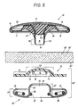
- Such a measure is applied to the rivet part 10 ', which, according to FIG. 5, is used for the attachment of the corresponding die part 30.
- a hollow shaft 12 which in its Shaft end 18 is provided with an end opening 16 ', which is why the tube interior 15 to the flange top 13, which points downward in Fig. 5, is open.
- the flange plate 11 is profiled differently compared to the embodiment of FIG. 2, which is why the depression 21 extends only to the inner flange area.
- a spherical cap 14 is provided, which flanges the peripheral region of the flange 11 and also holds an insert plate 59, which is underlaid on the flange 11.
- the foot piece 17 of the hollow shaft 12 is slightly conical instead of cylindrical, as in the first embodiment.
- the rivet part 10 ' is provided with a sealing material 63, which in this embodiment is initially applied in liquid form on the flange underside 13 of the finished rivet part 10' and cures there. This flows both into the depression 19 of the plate 11 and produces a plastic filling 64 there, as well as through the shaft opening 16 'into the tube interior 15 and forms a stopper 65 there.
- the plastic filling 64 covers both the conical foot piece 17 and even the adjacent area of the hollow shaft 12.
- This rivet part 10 ' serves, as already mentioned, for attaching a die part 30, which in turn consists of a structural unit 60' comprising two components in the present case.
- the second component of the unit 60 ' also consists of a prefabricated sealant, namely a profiled disc 70, which has the special appearance shown in the lower region of FIG. 5.
- the profiling can best be described as an ⁇ -shaped longitudinal profile, consisting of a central curvature 72, which is surrounded by an essentially flat ring 73.
- projections 75 On the concave side of the arch 72, namely in the interior 74 of the arch, there are projections 75, which in the present case consist of an annular circumferential collar. The collar 75 tapers off conically.
- This profiled disk 70 is now preassembled with the actual die part 30, which has the following appearance, which can be seen at the bottom of FIG. 5.
- the die part 30 also consists of a sheet metal body which can be divided into a flanged plate 31 and a dome 37.
- the dome 37 creates a "plate top 33 Oberseite pointing downward in FIG. 5 Closing opening 36, in which the actual matrix-shaped closing surfaces 32 are located.
- the dome 37 rises up on the underside of the plate 34 and produces a rivet receptacle 35 inside, which is accessible through a central opening 39 in the dome floor.
- the matrix-shaped closing surfaces come about here through a double S spring 32 known per se, the inner spring legs of which protrude through lateral slots 38 in the dome 37. When the above-described male part 20 or the structural unit 60 formed by it couple in and out, the inner legs spring radially into the slots 38.
- the dome 37 projects beyond the underside of the plate 34 by the amount which is adapted in profile to the above-described interior 74 of the curved disk 70.
- the unit 60 'mentioned from the two components 30, 70 comes together by simply axially pressing the preliminary products together.
- the profile disk 70 is pressed against the underside of the plate 34.
- the collar 75 is briefly deformed until it snaps through the narrowed opening 39 into the interior of the dome 37.
- the collar 76 then engages behind the undercut wall regions 66 of the dome 37, which is why there is a snap connection of the two components 30, 70 which ensures sufficient cohesion.
- the parts 30, 70 are coupled to one another to form a structural unit 60 ', which is handled as one piece in the processing machines now coming into play, which are used for riveting them to the fabric web 50'.
- Fig. 5 shows the decisive positioning of the components during the riveting process, for which purpose, however, the unit 60 'would have to be pre-assembled.
- This assembly 60 ' comes through the associated tool of the processing machine to lie on the back surface 52' of the fabric, while the above-described rivet part 10 'reaches the front surface 51'.
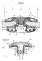
- the two tools of the processing machine move the two parts 10 ', 60' axially against each other, the hollow shaft 12 with its tube opening 16 'making its way through the supporting track 50' itself and at the same time in the apex area 76 of the profiled disk 70 from FIG. 6 Punch out recognizable base piece 77.
- a deformation 18 'of the shaft end can be seen from FIG. 6.
- the punched-out bottom piece 77 can remain inside the tube 15. However, this is immaterial because the sealing effect against the flow path of wind and weather, which is also indicated here by arrows 55, closes the plug interior 15 in this area of the plug 65.
- the lateral plastic fillings 64 of the sealing material 63 can be pressed together by interaction with the outer surface of the sealing washer 70 and ensure a circumferential seal in the track hole. 6, the edge zones of the supporting track hole can then also be pressed together between the mutually guided surfaces of the plastic filling 63 in the rivet part 10 on the one hand and the outer surface of the profiled disk 70 on the other hand; these plastic parts then act like two press jaws.
- Fig. 7 shows an alternative of a die part 10 ', which has the basic structure already described.
- a hat body 40 'already explained in connection with FIG. 1 is used here, which in principle has the same structure as in FIG. 1, which is why the previous description applies to this extent.
- the flange can have a somewhat modified profile 11 ', which produces the corresponding depression 69 for the brim 41.
- This hat body 40 ' is preassembled with the rivet part 10' to form a unit 80 according to FIG. 7.
- the hat body 40 is moved axially over the hollow shaft 12, which is also open here, as a result of which the free shaft edge 16 'cuts out a stopper from the hat cover 44, which here has a particularly pronounced wall thickness 67 due to an internal crowning. So that the tube interior 15 is already sealed.
- the hat cap 42 thus acts like a stocking which is pulled over the hollow shaft 12. From the top of the hat 44, the shaft end 18 protrudes in order to retract during the riveting process into the described rivet receptacle 35 of the die part and there with the rivet counter tool in the manner already apparent from FIG. 6 at 18 ' to be deformed.
- the hat body 40 or 40 ' can serve two applications, namely sealing means both in the male part 20 and indirectly, via the rivet part 10', in the female part 30. In this case, it is no longer necessary to use the profiled disk 70 described in connection with FIG. 5 for the die part 30.
- FIG. 8 shows a structural unit 90 which is modified compared to the embodiment of FIGS. 1 and 2, in which the shape of the male part 20 has been retained, but the hat body 91, which is likewise made of plastic, has a modified shape. It is therefore sufficient to describe only the differences. In all other respects, the previous description applies. Except for a recess 92, the inside of the hat 93 is solid. After the parts 20, 91 have been assembled, this recess 92 appears on the underside of the plate 24 and is used during the riveting process to center a tapered shaft end from the associated rivet part. This rivet part could also be solid in the sense of the rivet part 81 of FIG. 9, which will be described in more detail below.
- the top of the hat is provided with a recess 94, which is why a larger chamber 95 is formed in the interior of the pot when the assembly 90 is assembled.
- the plastic of the hat body 91 is elastically deformable when the rivet shaft penetrates into the interior of the pot and is displaced into the chamber 95 and compressed in itself. This promotes the strength of the rivet connection of the assembly 90 on a support track.
- Fig. 9 in a representation corresponding to FIG. 2, the parts 90 ', 81 used for mounting on a support track 50 are shown, but which have an alternative shape. In this case too, only the differences are to be described, while the previous description applies in all other respects.
- the rivet part 81 is made of solid metallic material.
- a shaft 82 is provided with a sharp tip 83 and is designed as a nail 84 on a flange 82.
- the plastic disc 48 already described in FIG. 2 can be assigned to this.
- a modified structural unit 90 ' is formed from the male part 20 and from an alternative hat body 85.
- the hat body 85 consists of metallic material, e.g. B. aluminum or copper.
- a rivet receptacle designed as a profiled through-hole 86 which, after assembly, is open to the rest of the pot cavity 25 according to FIG.
- the "cap” of this hat body 85 has a cylindrical circumferential surface 88 which, after being connected to the male part 20, initially only interacts with its inner wall surface 79 of the pot by friction.
- the bore 86 has an inner bead 87 in its end region, which narrows the bore to a smaller clear width 89 at this point.
- This clear width 89 is somewhat narrower than the diameter 96 of the associated nail 84 of the rivet part 81.
- the metallic hat body 85 initially generates a rigid abutment on the underside 24 of the assembly 90 'during the riveting process. As a result, the support track 50 is pressed off at this point and stripped off by the penetrating nail 84 when its tip 83 clears the way through the material of the support track 50.
Landscapes
- Insertion Pins And Rivets (AREA)
- Slide Fasteners, Snap Fasteners, And Hook Fasteners (AREA)
Applications Claiming Priority (2)
| Application Number | Priority Date | Filing Date | Title |
|---|---|---|---|
| DE3918375A DE3918375A1 (de) | 1989-06-06 | 1989-06-06 | Druckknopfverbindung |
| DE3918375 | 1989-06-06 |
Publications (3)
| Publication Number | Publication Date |
|---|---|
| EP0401574A2 true EP0401574A2 (fr) | 1990-12-12 |
| EP0401574A3 EP0401574A3 (fr) | 1991-05-08 |
| EP0401574B1 EP0401574B1 (fr) | 1994-09-28 |
Family
ID=6382141
Family Applications (1)
| Application Number | Title | Priority Date | Filing Date |
|---|---|---|---|
| EP90109424A Expired - Lifetime EP0401574B1 (fr) | 1989-06-06 | 1990-05-18 | Assemblage de bouton-pression |
Country Status (3)
| Country | Link |
|---|---|
| US (1) | US5003673A (fr) |
| EP (1) | EP0401574B1 (fr) |
| DE (2) | DE3918375A1 (fr) |
Cited By (5)
| Publication number | Priority date | Publication date | Assignee | Title |
|---|---|---|---|---|
| EP0482346B1 (fr) * | 1990-10-24 | 1994-05-18 | STOCKO Metallwarenfabriken Henkels und Sohn GmbH & Co | Bouton-pression |
| DE4411465C1 (de) * | 1994-04-01 | 1995-03-30 | Stocko Metallwarenfab Henkels | Wasserdichter Kappenniet für einen Druckknopf mit einer Stabfedermatrize |
| EP1038460A1 (fr) | 1997-09-22 | 2000-09-27 | Ykk Europe Ltd. | Bouton-pression |
| US6170135B1 (en) | 1997-10-23 | 2001-01-09 | Ykk Europe Ltd. | Watertight press fastener part |
| EP3886640B1 (fr) * | 2018-11-29 | 2022-10-05 | Daudé Fabrication | Bouton-pression étanche |
Families Citing this family (27)
| Publication number | Priority date | Publication date | Assignee | Title |
|---|---|---|---|---|
| DE4444333A1 (de) * | 1994-12-13 | 1996-06-20 | Happich Gmbh Gebr | Druckknopfartige Befestigungsvorrichtung |
| DE29502090U1 (de) * | 1995-02-09 | 1995-04-27 | Stocko Verschlußtechnik GmbH & Co., 42327 Wuppertal | Wendekugel für Druckknöpfe |
| US5579697A (en) * | 1995-08-29 | 1996-12-03 | Zeftek, Inc. | Auto rack panel gap sealing device |
| DE19824943A1 (de) * | 1998-06-04 | 1999-12-09 | Prym William Gmbh & Co Kg | Druckknopf |
| US6319015B1 (en) | 1999-08-23 | 2001-11-20 | Michael J. Faunce | Garment electrical connector |
| DE10015239A1 (de) * | 2000-03-27 | 2001-10-04 | Profil Verbindungstechnik Gmbh | Funktionselementanordnung, Funktionselement, Hilfsfügeteil, Zusammenbauteil und Verfahren zur Herstellung eines Zusammenbauteils |
| US6854988B2 (en) * | 2002-06-28 | 2005-02-15 | Koninklijke Philips Electronics N.V. | Mechanism for electrically connecting an electronic device to a garment |
| JP4221344B2 (ja) * | 2004-09-03 | 2009-02-12 | Ykk株式会社 | 止め具およびボタン |
| US20060213143A1 (en) * | 2005-03-24 | 2006-09-28 | Mcintyre Dan | Shingles and methods of producing shingles |
| US20080289076A1 (en) * | 2007-05-21 | 2008-11-27 | Jason Millward | Accessory and fastener therefore |
| US8561269B2 (en) * | 2010-09-17 | 2013-10-22 | Ykk Corporation | Fastener having a flexible base |
| USD678816S1 (en) * | 2010-12-23 | 2013-03-26 | Duraflex Hong Kong Limited | Snap button assembly |
| US20130227767A1 (en) * | 2012-03-05 | 2013-09-05 | Allen John BANCROFT | Helmet assembly and helmet fastening system |
| US20150272283A1 (en) * | 2014-04-01 | 2015-10-01 | Duraflex Hong Kong Limited | Washer for a snap fastener |
| CN104522943B (zh) * | 2014-12-25 | 2017-04-12 | 香港多耐福有限公司 | 一种按扣 |
| JP6749698B2 (ja) * | 2015-09-04 | 2020-09-02 | 国立研究開発法人科学技術振興機構 | コネクタ基板、センサーシステム及びウェアラブルなセンサーシステム |
| US9642398B1 (en) * | 2015-10-23 | 2017-05-09 | Te Connectivity Corporation | Wearable connector for an electronic textile |
| US10448774B1 (en) * | 2016-07-05 | 2019-10-22 | Daemian Brown | Arrangement for adjustable supporting dual panel shower curtain |
| US20190166920A1 (en) * | 2017-03-27 | 2019-06-06 | Nicholle Savoy | DèNude |
| JP6942038B2 (ja) * | 2017-12-05 | 2021-09-29 | 日本航空電子工業株式会社 | コネクタ |
| SE542380C2 (en) * | 2018-07-16 | 2020-04-21 | Inuheat Group Ab | Electrical connector |
| CN109764043B (zh) * | 2019-03-11 | 2024-09-27 | 江西省晶为光电科技有限公司 | 一种双向密封卡扣 |
| JP7178956B2 (ja) * | 2019-05-17 | 2022-11-28 | 日本航空電子工業株式会社 | 接続方法、接続構造および接続端子組立体 |
| WO2021102550A1 (fr) * | 2019-11-29 | 2021-06-03 | Incour Innovations Ltd. | Dispositif de fixation par bouton-pression et fermeture à languette à boutons-pression pour vêtement |
| JP7807994B2 (ja) * | 2022-06-27 | 2026-01-28 | 日本航空電子工業株式会社 | シート状導電部材およびコネクタ |
| JP2024033809A (ja) * | 2022-08-31 | 2024-03-13 | 日本航空電子工業株式会社 | コネクタおよびコネクタ組立体 |
| JP2024103091A (ja) * | 2023-01-20 | 2024-08-01 | 住友電装株式会社 | コネクタ |
Family Cites Families (15)
| Publication number | Priority date | Publication date | Assignee | Title |
|---|---|---|---|---|
| US573532A (en) * | 1896-12-22 | Separable button | ||
| JPS5325604Y2 (fr) * | 1974-05-21 | 1978-06-30 | ||
| DE2523146A1 (de) * | 1975-05-24 | 1976-12-02 | Wentzell Friedrich Dipl Kfm | Hohlnietartiges befestigungselement, insbesondere fuer druckknopfteile |
| JPS58164512U (ja) * | 1981-12-07 | 1983-11-01 | 日本ノ−シヨン工業株式会社 | 被服用スナツプ |
| DE3313351A1 (de) * | 1983-04-13 | 1984-10-18 | William Prym-Werke Kg, 5190 Stolberg | Nietpresse zur befestigung eines hart-kurzwarenartikels, wie eines druckknopfs, an einer traegerbahn |
| DE3313682A1 (de) * | 1983-04-15 | 1984-10-18 | William Prym-Werke Kg, 5190 Stolberg | Nietpresse zur befestigung von hart-kurzwarenartikeln, wie druckknopfteilen, an flexiblen traegerbahnen |
| DE3313652A1 (de) * | 1983-04-15 | 1984-10-18 | William Prym-Werke Kg, 5190 Stolberg | Betaetigungsvorrichtung fuer eine nietpresse von kurzwarenartikeln |
| DE3501224A1 (de) * | 1985-01-16 | 1986-07-17 | William Prym-Werke GmbH & Co KG, 5190 Stolberg | Nietpresse zur befestigung eines schliessfunktions-teils, insbesondere druckknopfteils, an einer traegerbahn, wie einem kleidungsstueck |
| GB2171446A (en) * | 1985-02-15 | 1986-08-28 | Kane Ind Co Ltd M | Socket for snap fastener |
| US4596349A (en) * | 1985-05-02 | 1986-06-24 | William Prym-Werke Kg | Machine for applying articles of hardware to textile materials and the like |
| FR2584782B1 (fr) * | 1985-07-10 | 1987-11-27 | Jaunet Sa Jacques | Dispositif pour fixer une plaque metallique sur une nappe, notamment sur un article de mode et son application a la fixation d'une marque de couturier |
| JPS62111409U (fr) * | 1985-12-28 | 1987-07-16 | ||
| US4851883A (en) * | 1986-09-11 | 1989-07-25 | Minolta Camera Kabushiki Kaisha | Copying machine having an auto-paper selection function |
| DE8915363U1 (de) * | 1989-08-29 | 1990-04-26 | William Prym-Werke GmbH & Co KG, 5190 Stolberg | Knopf, insbesondere für Kleidungsstücke |
| DE8910386U1 (de) * | 1989-08-31 | 1989-11-16 | William Prym-Werke GmbH & Co KG, 5190 Stolberg | Verbindbarer Hartkurzwaren-Artikel mit einem Funktionsteil, wie einem Druckknopfteil |
-
1989
- 1989-06-06 DE DE3918375A patent/DE3918375A1/de not_active Withdrawn
-
1990
- 1990-05-18 EP EP90109424A patent/EP0401574B1/fr not_active Expired - Lifetime
- 1990-05-18 DE DE59007308T patent/DE59007308D1/de not_active Expired - Fee Related
- 1990-06-05 US US07/533,424 patent/US5003673A/en not_active Expired - Fee Related
Cited By (9)
| Publication number | Priority date | Publication date | Assignee | Title |
|---|---|---|---|---|
| EP0482346B1 (fr) * | 1990-10-24 | 1994-05-18 | STOCKO Metallwarenfabriken Henkels und Sohn GmbH & Co | Bouton-pression |
| DE4411465C1 (de) * | 1994-04-01 | 1995-03-30 | Stocko Metallwarenfab Henkels | Wasserdichter Kappenniet für einen Druckknopf mit einer Stabfedermatrize |
| EP0674858A3 (fr) * | 1994-04-01 | 1996-06-19 | Stocko Verschlusstechnik Gmbh | Rivet à calotte étanche pour un bouton à pression et méthode pour leur liaison. |
| EP1038460A1 (fr) | 1997-09-22 | 2000-09-27 | Ykk Europe Ltd. | Bouton-pression |
| US6170129B1 (en) | 1997-09-22 | 2001-01-09 | Ykk Europe Ltd. | Press fastener |
| DE19741779B4 (de) * | 1997-09-22 | 2004-10-28 | Stocko Fasteners Gmbh | Druckknopf |
| US6170135B1 (en) | 1997-10-23 | 2001-01-09 | Ykk Europe Ltd. | Watertight press fastener part |
| DE19746908C2 (de) * | 1997-10-23 | 2001-02-22 | Stocko Fasteners Gmbh | Wasserdichter Druckknopf |
| EP3886640B1 (fr) * | 2018-11-29 | 2022-10-05 | Daudé Fabrication | Bouton-pression étanche |
Also Published As
| Publication number | Publication date |
|---|---|
| EP0401574B1 (fr) | 1994-09-28 |
| DE59007308D1 (de) | 1994-11-03 |
| US5003673A (en) | 1991-04-02 |
| EP0401574A3 (fr) | 1991-05-08 |
| DE3918375A1 (de) | 1990-12-13 |
Similar Documents
| Publication | Publication Date | Title |
|---|---|---|
| EP0401574B1 (fr) | Assemblage de bouton-pression | |
| EP0758039B1 (fr) | Rail d'ancrage pour la technique du bâtiment | |
| EP0842733A2 (fr) | Procédé pour attacher un élément fonctionnel, élément fonctionnel, ensemble de montage, matrice et tête de pose | |
| EP1068458A1 (fr) | Dispositif d'assemblage pour la jonction de deux composants, combinaison du dispositif d'assemblage avec les deux composants et procede d'obtention d'une jonction entre deux composants | |
| DE102008052383A1 (de) | Zusammenbauteil bestehend aus einem Befestigungselement und einem Blechteil sowie ein Verfahren zur Herstellung eines solchen Zusammenbauteils | |
| WO1999049227A2 (fr) | Procede, outil et poinçon pour relier des composants a une plaque | |
| EP2961638B1 (fr) | Support de galerie de toit ainsi que système de galerie de toit, et véhicule équipé d'un tel système de galerie de toit | |
| DE10353642A1 (de) | Funktionselement, Zusammenbauteil bestehend aus dem Funktionselement in Kombination mit einem Blechteil, Verfahren zur Herstellung des Zusammenbauteils sowie Verfahren zur Herstellung des Funktionselements | |
| EP1609561B1 (fr) | Procédé pour fabriquer un composant d'assemblage comprenant une pièce de tôle et un élément fonctionnel fixé sur cette pièce de tôle, pièce de tôle ainsi qu' un composant d'assemblage | |
| EP1985408A2 (fr) | Elément fonctionnel destiné à l'application sur un élément en tôle, composant fabriqué à partir de celui-ci et procédé d'application de l'élément fonctionnel sur un élément en tôle | |
| EP1346160A1 (fr) | Elément tourillon présentant une partie tige et une tête sphérique, composant d'assemblage et procédé de fabrication d'un tel élément tourillon | |
| WO2007065398A1 (fr) | Procédé pour appliquer un élément fonctionnel sur un matériau plat et liaison entre un élément fonctionnel et un matériau plat | |
| EP0489067B1 (fr) | Fermeture a boutons, en particulier pour les vetements | |
| DE102005031916B4 (de) | Halbhohlstanzniet zum mechanischen Fügen und Verfahren zum Herstellen einer Fügeverbindung | |
| DE4016077A1 (de) | Druckknopfverbindung | |
| DE102008023044B4 (de) | Verfahren zum Anbringen eines Füge- oder Funktionselementes an einem plastisch verformbaren Flachmaterial | |
| EP0320633B1 (fr) | Bouton-pression | |
| DE19950719B4 (de) | Arbeitsverfahren zur Herstellung einer Nietverbindung sowie Niet, Nietwerkzeug und Anwendung derselben | |
| EP3564545B1 (fr) | Composant d'assemblage comprenant un composant et d'un élément doté d'une partie de tête et d'un col disposé sur un côté de la partie de tête ainsi que son procédé de fabrication | |
| DE4411465C1 (de) | Wasserdichter Kappenniet für einen Druckknopf mit einer Stabfedermatrize | |
| DE9014692U1 (de) | Druckknopf | |
| WO2008138286A2 (fr) | Procédé pour installer un élément d'assemblage ou fonctionnel sur un matériau plat et élément d'assemblage ou fonctionnel utilise a cet effet | |
| DE8915362U1 (de) | Druckknopfverbindung | |
| DE102004030223A1 (de) | Verfahren zur Herstellung eines Zusammenbauteils bestehend aus einem Blechteil und einem an diesem angebrachten Funktionselement, Blechteil sowie Funktionselement | |
| DE1552836C (de) | Vorrichtung zum Befestigen von Stanzmuttern an einem Blech. Ausscheidung aus: 1400869 |
Legal Events
| Date | Code | Title | Description |
|---|---|---|---|
| PUAI | Public reference made under article 153(3) epc to a published international application that has entered the european phase |
Free format text: ORIGINAL CODE: 0009012 |
|
| AK | Designated contracting states |
Kind code of ref document: A2 Designated state(s): BE DE ES FR IT SE |
|
| 17P | Request for examination filed |
Effective date: 19901128 |
|
| PUAL | Search report despatched |
Free format text: ORIGINAL CODE: 0009013 |
|
| AK | Designated contracting states |
Kind code of ref document: A3 Designated state(s): BE DE ES FR IT SE |
|
| 17Q | First examination report despatched |
Effective date: 19921210 |
|
| RAP1 | Party data changed (applicant data changed or rights of an application transferred) |
Owner name: WILLIAM PRYM GMBH & CO. KG |
|
| ITF | It: translation for a ep patent filed | ||
| GRAA | (expected) grant |
Free format text: ORIGINAL CODE: 0009210 |
|
| AK | Designated contracting states |
Kind code of ref document: B1 Designated state(s): BE DE ES FR IT SE |
|
| PG25 | Lapsed in a contracting state [announced via postgrant information from national office to epo] |
Ref country code: BE Effective date: 19940928 Ref country code: ES Free format text: THE PATENT HAS BEEN ANNULLED BY A DECISION OF A NATIONAL AUTHORITY Effective date: 19940928 |
|
| ET | Fr: translation filed | ||
| REF | Corresponds to: |
Ref document number: 59007308 Country of ref document: DE Date of ref document: 19941103 |
|
| PG25 | Lapsed in a contracting state [announced via postgrant information from national office to epo] |
Ref country code: SE Effective date: 19941228 |
|
| PLBE | No opposition filed within time limit |
Free format text: ORIGINAL CODE: 0009261 |
|
| STAA | Information on the status of an ep patent application or granted ep patent |
Free format text: STATUS: NO OPPOSITION FILED WITHIN TIME LIMIT |
|
| 26N | No opposition filed | ||
| PGFP | Annual fee paid to national office [announced via postgrant information from national office to epo] |
Ref country code: DE Payment date: 20080326 Year of fee payment: 19 |
|
| PGFP | Annual fee paid to national office [announced via postgrant information from national office to epo] |
Ref country code: IT Payment date: 20080520 Year of fee payment: 19 |
|
| PGFP | Annual fee paid to national office [announced via postgrant information from national office to epo] |
Ref country code: FR Payment date: 20080327 Year of fee payment: 19 |
|
| REG | Reference to a national code |
Ref country code: FR Ref legal event code: ST Effective date: 20100129 |
|
| PG25 | Lapsed in a contracting state [announced via postgrant information from national office to epo] |
Ref country code: FR Free format text: LAPSE BECAUSE OF NON-PAYMENT OF DUE FEES Effective date: 20090602 |
|
| PG25 | Lapsed in a contracting state [announced via postgrant information from national office to epo] |
Ref country code: DE Free format text: LAPSE BECAUSE OF NON-PAYMENT OF DUE FEES Effective date: 20091201 |
|
| PG25 | Lapsed in a contracting state [announced via postgrant information from national office to epo] |
Ref country code: IT Free format text: LAPSE BECAUSE OF NON-PAYMENT OF DUE FEES Effective date: 20090518 |